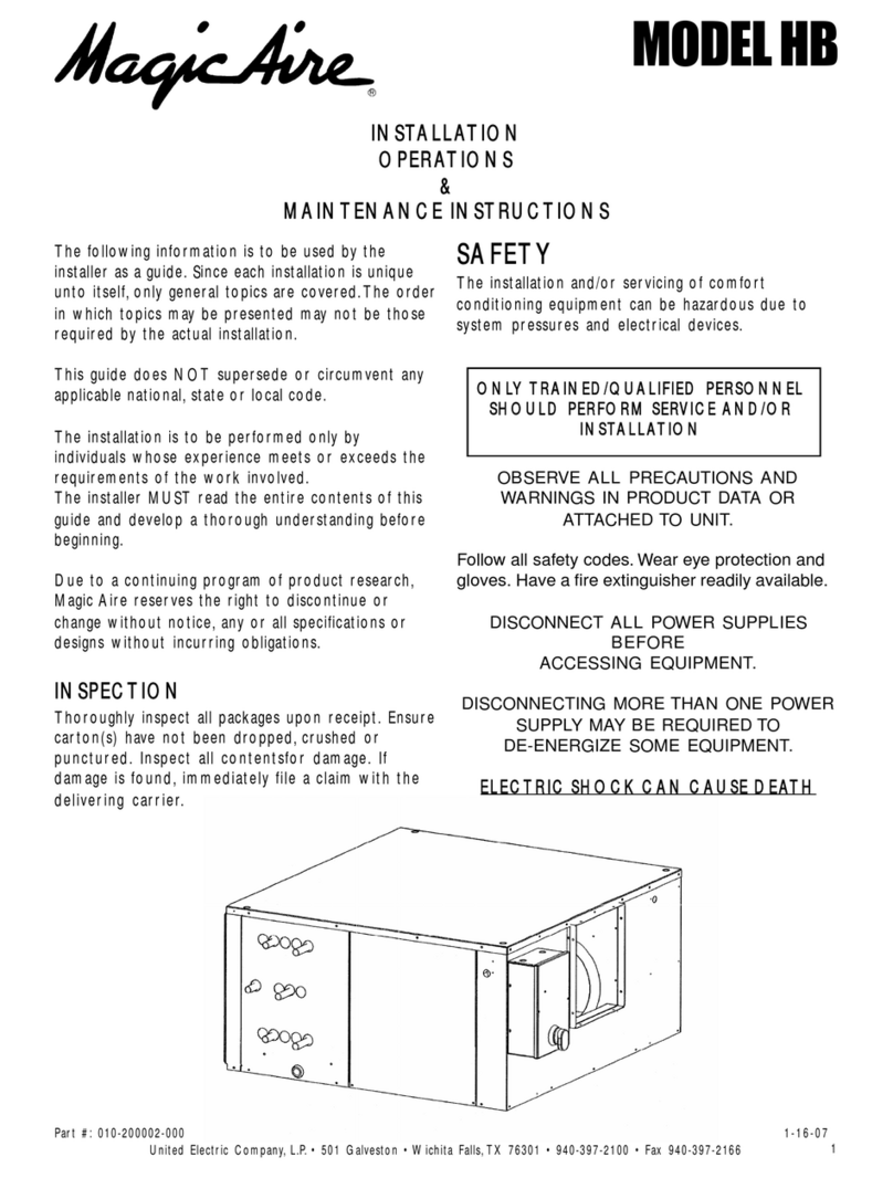
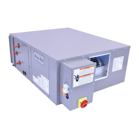
Magic Aire HB Series User manual

010-200002-000 Page 1 HB IOM 1.1 2-13-2014
AIR HANDLERS AND FAN
COILS
t ĂƌƌĂŶƚLJZĞŐŝƐƚƌĂƟŽŶĂŶĚ^ƚĂƌƚ-up Report
Warranty Registration Form: Complete
and submit this form within ten (10) days of
start-up to comply with the terms of the
Magic Aire warranty. Form must be com-
pleted to clearly indicate startup for each
unit being registered.
Mail form(s) to Magic Aire
Warranty Department
501 Galveston St.
Wichita Falls, TX, 76301 or
Email customer.service@MagicAire.com
STARTUP REPORT
Group Checklist Item Yes No
Electrical/Operational
Have red shipping screws been removed from blower discharge?
Does electrical service correspond to unit nameplate?
-Nameplate Supply Voltage/Phase: Rated_________ Measured___________
-Nameplate Rated FLA motor current: Rated_______ Measured__________
Does all field wiring conform to unit wiring diagram?
Is field-provided freeze protection present? (for DX and hydronic coils)
Is fan wheel turning the correct direction?
Are mixing box dampers operating properly?
Is the filter clean?
Structural
Is unit properly supported?
Is unit installed level (necessary for proper condensate drainage)?
Is properly sized condensate trap present?
Is the condensate disposal system operating correctly?
Is auxiliary external condensate drain pan installed as recommended by IOM? (not
required for valid warranty)
DX Sys-
tems
Is expansion valve sensing bulb properly installed and insulated?
Is Heat Pump Bypass Kit (HPK) present if required?
Is the DX system charged per the condensing unit mfr’s instructions?
Piping
Check
Is unit piping correct and insulated to prevent condensation?
Are the control valve packages piped correctly?
Are Valve packages properly insulated?
Are there any leaks detected: interior to unit, at connections, or at valve packages?
Hydronic
Systems
Have customer-provided Freeze Protection measures been taken, such as Low
Limit Thermostats and glycol (antifreeze) heat transfer fluids?
Does the hydronic system include a pressure relief valve or other pressure relief
device to protect the coil from operating pressures beyond the nameplate design
working pressure rating?
Are coils equipped with control valves to stop fluid flow to save energy and prevent
cabinet condensation (wild coil in cooling) when heating/cooling is not required?
Does setting for overload device (factory or field-provided) match motor FLA?
Job Name City
Sales Order # Unit Tag
Model Number Serial Number
Installer Quantity of Units

010-200002-000 Page 2 HB IOM 1.1 2-13-2014
THIS PAGE INTENTIONALLY LEFT BLANK

010-200002-000 Page 3 HB IOM 1.1 2-13-2014
/ŶƐƚĂůůĂƟŽŶ ^ƚĂƌƚ-Up
and Service
/ŶƐƚƌƵĐƟŽŶƐ
HB Series Horizontal Air Handler
Installation, Operation and Maintenance
Manual
Topic Page
Warranty Regristration Form 1-2
SAFETY CONSIDERATIONS 4-5
INTRODUCTION 4-5
UNPACKING-Remove Shipping Screws 5
PREINSTALLATION 6
Rigging 6
INSTALLATION 7
Unit Suspension 7
External Vibration Isolators 7
Ductwork 8
Electrical 9-14
Service Clearance 15
Condensate Drain 16
Mixing Box Actuator 16-17
Mixing Box Air Sensor 18
Mixing Box 18
Mixing Box Linkage 19-20
Install Sheaves on Motor and Fan
Shafts 20-21
Install V-Belts 21-22
Steam Coil Piping
Recommendations 23-25
Coil Freeze-Up Protection 25-26
Refrigerant Piping, Direct Expansion
(DX) Coils 26-27
START-UP 28-29
SERVICE 29-33
Winter Shutdown 29-30
Coil/Drain Pan Service 31-32
Water Quality Guidelines 33

010-200002-000 Page 4 HB IOM 1.1 2-13-2014
Magic Aire HB Series units are belt drive
Horizontal Air Handlers delivering nominal
airflows of 400 to 8000cfm and nominal
cooling capacities of 1 to 20 tons. Units
may be specified with chilled water or DX
cooling coils and hot water or steam heating
coils to meet space cooling loads or heating
loads or both.
Factory Installed Options:
-Discharge Electric Heaters (single point con-
nection)
-Motor Start/Stop Station
-Face & Bypass dampers
Field-installed accessories include:
-factory pre-set valve packages
-mixing box
-mixing box controls
-Filter box with MERV 8 and MERV 13 filters.
-discharge grille plenum
How to Use this Manual:
This manual gives instructions regarding in-
stallation, operation and maintenance for the
HB Series air handling units. For more infor-
mation refer to:
Catalog brochure for unit dimensions,
options, guide specifications and perfor-
mance information.
New Magic 4 software for faster selection
of new equipment.
Website www.magicaire.com for re-
placement parts guide, software down-
loads, product data and contact info for
your local Magic Aire representative.
Replacement Parts – Identify parts
needed using the replacement parts
guide available at www.magicaire.com.
Use these instructions in conjunction with
other appropriate instructions, including but
not limited to those instructions supplied with
the outdoor unit (if applicable). Installation
must comply with all applicable local codes.
GENERAL
Installation and maintenance are to be per-
formed only by qualified personnel who are fa-
miliar with local codes and regulations and are
experienced with HVAC equipment of this type.
WARNING: Sharp edges, coil surfaces
and rotating fans are a potential injury
hazard – avoid contact.
WARNING: Hazardous voltage – Discon-
nect and Lock Out all incoming power
sources before servicing or installing unit.
ELECTRIC SHOCK CAN CAUSE DEATH.
WARNING: This equipment may be in-
stalled well above finished floor—Use ex-
treme caution when working at heights.
SAFETY WARNING:
Installer should pay particular attention to
the following words:
NOTE–intended to clarify or make instal-
lation easier.
CAUTION–given to prevent equipment
damage.
WARNING–to alert installer that personal
injury and/or equipment damage may
result if installation procedure is not
properly followed.
HB Series Horizontal Air Handler
Installation, Operation and Maintenance
Manual
UNPACKING-CHECK FOR DAMAGE!
Immediately inspect each unit for dam-
age upon receipt.
Inspect units for external and concealed
damage immediately.
File any damage claims in accordance
with Magic Aire Freight Damage Policy
and Terms and Conditions (available at
www.magicaire.com).
Do not repair damaged units without
written authorization.
Protect stored units from damage.

010-200002-000 Page 5 HB IOM 1.1 2-13-2014
WARNING
CHECK the assembly and component weights to
be sure that the rigging equipment can handle
them safely.
Note also, the centers of gravity and any specific
rigging instructions.
CHECK for adequate ventilation so that fumes will
not migrate through ductwork to occupied spaces
when welding or cutting inside air-handling unit
cabinet or plenum.
WHEN STEAM CLEANING COILS be sure that
the area is clear of personnel.
DO NOT attempt to handle access covers and re-
movable panels on outdoor units when winds are
strong or gusting until you have sufficient help to
control them. Make sure panels are properly se-
cured while repairs are being made to a unit.
DO NOT remove access panel fasteners until fan
is completely stopped. Pressure developed by a
moving fan can cause excessive force against the
panel which can injure personnel.
DO NOT work on dampers until their operators are
disconnected.
BE SURE that fans are properly grounded before
working on them.
Failure to follow these warnings could result in per-
sonal injury or equipment damage.
DANGER
NEVER enter an enclosed fan cabinet or reach into
a unit while the fan is running.
LOCK OPEN AND TAG the fan motor power dis-
connect switch before working on a fan. Take fuses
with you and note removal on tag. Electric shock
can cause personal injury or death.
LOCK OPEN AND TAG the electric heat coil power
disconnect switch before working on or near heat-
ers.
Failure to follow these warnings could lead to per-
sonal injury or death.
UNPACKING-CAUTION!
After unpacking the blower section,
REMOVE RED SHIPPING SCREWS
from the blower discharge flanges as indi-
cated in Figures 1 and 2. These screws
stabilize the fans during shipping and need
to be removed.
CAUTION! Not removing red shipping
screws can result in unsatisfactory vibration
or blower noise or excessive air recircula-
tion.
Figure 1
Remove Red Shipping Screws
(4 per blower discharge—single discharge
shown)
Figure 2
Remove Red Shipping Screws
(one from each blower rail—two total)

010-200002-000 Page 6 HB IOM 1.1 2-13-2014
PREINSTALLATION
1. Check items received against packing list.
2. Do not stack unit components or accessories
during storage. Stacking can cause damage
or deformation.
3. If unit is to be stored for more than 2 weeks
prior to installation, observe the following
precautions:
a. Choose a dry storage site that is rea-
sonably level and sturdy to prevent un-
due stress or permanent damage to the
unit structure or components. Do not
store unit on vibrating surface. Damage
to stationary bearings can occur. Set
unit off ground if in heavy rain area.
b. Remove all fasteners and other small
parts from jobsite to minimize theft. Tag
and store parts in a safe place until
needed.
c. Cover entire unit with a tarp or plastic
coverall. Extend cover under unit if
stored on ground. Secure cover with
adequate tie downs or store indoors. Be
sure all coil connections have protective
shipping caps.
d. Monthly — Remove tarp from unit, enter
fan section through access door or
through fan inlet, and rotate fan and
motor slowly by hand to redistribute the
bearing grease and to prevent bearing
corrosion.
Rigging — Do not remove shipping skids or pro-
tective covering until unit is ready for final place-
ment. Use slings and spreader bars as applica-
ble to lift unit. Do not lift unit by coil connections
or headers.
Do not remove protective caps from coil
piping connections until ready to connect
piping.
Do not remove protective cover or grease
from fan shaft until ready to install sheave.
Lay rigid temporary protection such as ply-
wood walkways in unit to prevent damage to
insulation or bottom panel during installa-
tion.
WARNING-AUXILIARY DRAIN PAN
RECOMMMENDED:
The International Mechanical Code (IMC)
section 307.2.3 requires the use of auxil-
iary drain pans. Many municipalities
have adopted this code.
Magic Aire holds that this practice repre-
sents the standard for professional instal-
lation whether or not this code has been
adopted in a specific municipality or terri-
tory. As such, water damages that would
have been prevented had an auxiliary
pan been deployed will not be considered
for compensation. This position is taken
regardless of whether the source of the
moisture was specified as a potential fail-
ure mode in the applicable building code
or not. A freeze burst, cracked drain pan,
failed weld, or corrosion induced leak are
some of the potential failure modes that
are mitigated when an auxiliary pan is
properly installed. Professional installers
recognize the value of protecting custom-
er assets against foreseeable events.
Customers who choose to avoid the cost
of common protective measures waive
their right to seek damages when those
foreseeable events occur. If the product
is located above a living space or where
damage may result from condensate
overflow, install a watertight pan of corro-
sion-resistant metal beneath the unit to
catch over-flow which may result from
clogged drains or from other reasons.
Provide proper drain piping for this auxil-
iary pan. Consult local codes for addition-
al precautions before installation.

010-200002-000 Page 7 HB IOM 1.1 2-13-2014
INSTALLATION
UNIT SUSPENSION
Horizontal Units: Acceptable forms of unit sus-
pension are shown in Fig. 3 and 4. A field-
supplied platform mount is recommended, espe-
cially for larger unit sizes. Units can also be sup-
ported by suspending the unit from crossbeams
at the front and rear. Ensure that suspension
rods are secured to adequately support the unit
and that the rods extend entirely through their
associated fasteners. It is recommended that
framing be constructed from angle iron or
formed-strut materials.
Fig. 3
Unit
Suspension
With Mixing Boxes: HB units sizes 30-80 with
mixing boxes should be supported with cross-
beams at each end of the unit and at the duct
connection side of the mixing box. Sizes 04-20
with mixing box—no additional support is re-
quired.
WARNING! INSURE THAT UNIT IS ADE-
QUATELY SUPPORTED FROM STRUCTURE
TO PREVENT DAMAGE OR INJURY CAUSED
BY FALLING EQUIPMENT! If uncertain about
how to connect to the structure, consult a
qualified structural engineer.
Fig. 4
Unit
Suspension

010-200002-000 Page 8 HB IOM 1.1 2-13-2014
INSTALLATION—DUCTWORK (CONT’D)
Fig. 6 — HB size 60 and 80 Duct
Connections
DUCTWORK CONNECTIONS
Install supply and return ductwork to the
unit as required for the application. Note
that free discharge or free return is ac-
ceptable.
Return Ductwork: Install return ductwork
by attaching one side of a field-provided
flexible duct connector to the duct flange
on the return side of the unit (filter side).
Attach the other side of the flexible duct
connector to the return ductwork. Seal the
connections using duct mastic or HVAC
tape.
Supply Ductwork—Unit Sizes 04-40: Install
supply ductwork by attaching one side of a field-
provided flexible duct to the fan discharge duct
collar on the front of the unit. Attach the other
side to the supply ductwork. Seal the connec-
tions using duct mastic or HVAC tape. Refer to
Figure 5.
Supply Ductwork—Unit Sizes 60-80: Install
supply ductwork by attaching a field-provided
supply duct plenum over the fan discharges.
Supply duct plenum size is critical to fan perfor-
mance—size as indicated in Figure 6.
CAUTION: DO NOT USE PANTS-LEG TYPE
DISCHARGE DUCT AT THE FAN DISCHARG-
ES. The fans achieve rated performance ONLY
when installed with the supply duct plenum.
Fig. 5 — HB size 04 to 40
Duct Connections
Attach the supply duct plenum to the supply duct
using a flexible connector. Seal the connections
using duct mastic or HVAC tape. Refer to Fig-
ure 6.
NOTE: It is acceptable to omit the flexible duct
connectors, but this may allow normal operating
vibration or noise to transfer through the duct sys-
tem leading to customer complaints.
Size all ductwork according to SMACNA and
ASHRAE duct design standards.

010-200002-000 Page 9 HB IOM 1.1 2-13-2014
INSTALLATION-ELECTRICAL
Typical wiring diagrams are shown on the fol-
lowing pages FOR REFERENCE. Always re-
fer to the wiring diagram on the air handling unit
for actual wiring.
Connect electrical service to unit. Refer to unit
wiring diagram. NOTE: CHECK MOTOR RAT-
ING PLATE FOR CORRECT LINE VOLTAGE.
For power supply connection, route field power
wiring to Motor Start/Stop Station (MSS) dis-
connect switch (if provided) or motor leads in
the junction box (j-box).
Refer to nameplate FLA, maximum overcurrent
protection device (MOPD) and minimum circuit
ampacity (MCA). Also refer to wiring diagram
affixed to unit to make control and power wiring
connections.
Installer is responsible for power wiring, branch
circuit over current protection, NOTE: Motor
provided may or may not have internal thermal
overload protection. Units ordered with Motor
Start/Stop (MSS) option or Factory Electric
Heat include motor starter with overload if re-
quired for the factory-provided motor.
WARNING! Units ordered “j-box only” may
need additional field-provided motor overload
protection (all 3-phase motors and some single
phase motors).
NOTE: Units with Junction Box option have
4x4 J-box mounted on outside of unit. Refer to
dimensional drawings.
NOTE: Units with factory installed electric heat-
ers have fan starter and overload (if required)
located inside the electric heat control box.
DANGER
NEVER enter an enclosed fan cabinet or reach into
a unit while the fan is running.
LOCK OPEN AND TAG the fan motor power dis-
connect switch before working on a fan. Take fuses
with you and note removal on tag. Electric shock
can cause personal injury or death.
LOCK OPEN AND TAG the electric heat coil power
disconnect switch before working on or near heat-
ers.
Failure to follow these warnings could lead to per-
sonal injury or death.
DANGER
WARNING: Hazardous voltage. Only qualified
personnel must install the electrical service. Dis-
connect and Lock Out all incoming power sources
before connecting to electrical service.
WARNING: This appliance must be permanently
grounded in accordance with the National Electrical
Code and local code requirements.
WARNING: For use with copper conductors only.
NOTE: When installing the AEH auxiliary elec-
tric heat accessory, the heater control box con-
tains the motor starter and allows for single-
point line connection (one power circuit for both
electric heater and fan motor). Motor overload
is provided, when required, with the motor start-
er.
WARNING: CHECK FACTORY OR FIELD
PROVIDED OVERLOAD DEVICE SETTING—
MAKE SURE IT IS EQUAL TO THE MOTOR
FLA AT RATED VOLTAGE. Improper setting
may result in equipment malfunction, equip-
ment failure, or fire or other hazardous con-
dition leading to property damage or per-
sonal injury or death.

010-200002-000 Page 10 HB IOM 1.1 2-13-2014
LEGEND
NOTES:
1. These diagrams
represent the factory-
installed MSS option.
If the j-box option is
provided, an arrange-
ment like this may be
field-provided and
installed to allow the
customer's controls to
start and stop the fan.
Selection of field pro-
vided and installed
electrical components
is the responsibility of
the installer.
2. MSS provides sin-
gle-speed fan motor
control and includes
lockable, non-fused
disconnect switch,
75VA 24V control
transformer, fan relay
or contactor or starter
(with overload if
required), low voltage
terminal block and
indoor enclosure.
3. Typical wiring is
shown. For exact wir-
ing, refer to the wiring
diagram provided with
the unit. 4. Factory-
installed electric heat
includes the function-
ality of the MSS, so
MSS is not required.
5. Refer to the follow-
ing pages for j-box
and electric heat op-
tions.
6. Units ordered for
208V-240V voltage
selection are factory
wired for 240V. Field
may rewire motor and
transformer primary
tap for operation at
208V.
INSTALLATION-ELECTRICAL (cont’d) MOTOR START-STOP STATION TYPICAL
WIRING DIAGRAMS

010-200002-000 Page 11 HB IOM 1.1 2-13-2014
JUNCTION-BOX ONLY OPTION TYPICAL
WIRING DIAGRAMS
INSTALLATION-ELECTRICAL (cont’d)
NOTES:
1. The J-Box option has
factory-installed motor wir-
ing terminated in a 4x4
junction box on the outside
of the HB series unit, ready
for connection to field wir-
ing.
2. J-Box option does not
include disconnect switch,
starter or low voltage con-
trols.
3. An arrangement similar
to MSS wiring (see typical
wiring diagrams previous
page) may be field-
provided and installed to
allow the customer's con-
trols to start and stop the
fan. Selection of field pro-
vided and installed electri-
cal components is the re-
sponsibility of the installer.
CAUTION
With 2-speed motor, make sure that only one speed winding is energized at a time.
Energizing both windings simultaneously will result in motor damage and will void mo-
tor warranty. Magic Aire strongly recommends use of an isolation relay or similar de-
vice to insure that only one winding is energized.

010-200002-000 Page 12 HB IOM 1.1 2-13-2014
FACTORY ELECTRIC HEAT OPTION
TYPICAL WIRING DIAGRAMS
INSTALLATION-ELECTRICAL (cont’d)
NOTES:
1. Motor Start/Stop Station (MSS) not required
when factory-installed electric heat is selected. The
electric heater contains the fan motor starter and
low-voltage controls with “single-point-line” power
connection.
2. See the unit wiring diagram for actual wiring.

010-200002-000 Page 13 HB IOM 1.1 2-13-2014
FACTORY ELECTRIC HEAT OPTION
TYPICAL WIRING DIAGRAMS
INSTALLATION-ELECTRICAL (cont’d)
NOTES:
1. Motor Start/Stop Station (MSS) not required
when factory-installed electric heat is selected. The
electric heater contains the fan motor starter and
low-voltage controls with “single-point-line” power
connection.
2. See the unit wiring diagram for actual wiring.

010-200002-000 Page 14 HB IOM 1.1 2-13-2014
NOTES:
1. This option is not usual but may be provid-
ed when custom heaters are needed. Motor
Start/Stop Station (MSS) not required when
AEH accessory field-installed electric heat is
selected. The electric heater contains the fan
motor starter and low-voltage controls with
“single-point-line” power connection.
2. Units will have “Full Line Break” heater
contactor (HC1) starting in 2012. See the
unit wiring diagram for actual wiring.
3. NOT ALL POSSIBLE WIRING AR-
RANGEMENTS SHOWN. REFER TO UNIT
WIRING DIAGRAM FOR ACTUAL WIRING.
AUXILIARY ELECTRIC HEAT (AEH)
FIELD INSTALLED ACCESSORY
TYPICAL WIRING DIAGRAMS
INSTALLATION-ELECTRICAL (cont’d)
240V-1ø:1-6kW
(Single Element)
240V-3ø:1-10kW, 480V-
3ø:2-20kW
(Star Wiring)
Field splice at
AHU j-box.
Field splice at AHU j-
box.

010-200002-000 Page 15 HB IOM 1.1 2-13-2014
HB Series
Service Clearances

010-200002-000 Page 16 HB IOM 1.1 2-13-2014
Mixing Box Actuator
MIXING BOX ACTUATOR ASSEMBLY (Fig. 8 and 9)
— To assemble the mixing box actuator:
1. Press logic module onto actuator.
2. Remove lock nut from swivel nut assembly. Place
swivel nut assembly into slot on actuator arm.
Hand tighten lock nut onto swivel nut assembly.
Swivel nut assembly will need to be adjusted once
installed for proper actuator motion.
3. Attach actuator arm assembly to actuator with four
1/4-in. screws. Arm may need to be repositioned
Fig. 7 — Condensate Drain
INSTALLATION
Condensate Drain — Install a trapped condensate
drain line at unit drain connection. All HB units have a
3/4 in. FPT condensate drain connection.
Measure maximum design negative static pressure up-
stream from the fan. Referring to Fig. 7, height “H” must
be equal to or larger than negative static pressure at
design operating conditions. Prime enough water in
trap to prevent losing seal (Differential 1). When the fan
starts, Differential 2 is equal to the maximum negative
static pressure.
Provide freeze-up protection as required to insure relia-
ble condensate drainage. Freeze protection measures
are customer-supplied and installed.
INSTALLATION
Condensate Drain — To prevent excessive build-
up of condensate in drain pan, adequate trap clear-
ance (trap depth) must be provided beneath the unit
as indicated in Fig. 7. See Installation, Condensate
Drain section for additional details.
once installed to ensure proper actuator
motion.
Fig. 8 — Actuator Assembly
Fig. 9— Assembled Actuator

010-200002-000 Page 17 HB IOM 1.1 2-13-2014
ACTUATOR INSTALLATION — To install the actuator:
1. Align actuator so that the actuator linkage arm will
have enough clearance for full range of motion.
Refer to Fig. 10-13. Align center line of the actuator
as close to the centerline of DR4 as possible. See
Fig. 11 and 12. Use at least 4 self-drilling screws to
mount directly to top of unit.
2. Place linkage arm assembly (linkage arm and swiv-
el nut arm) onto DR4 as shown in Fig. 11 and 12.
Do not tighten to DR4 as adjustments need to be
made.
3. Place linkage rod between actuator arm and link-
age arm on DR4. See Fig. 11. Linkage rod may
need to be cut to length. Ensure actuator arm and
linkage arm are parallel.
4. Ensure linkage assemblies are properly secured as
shown in the linkage assembly instructions sent
with the unit.
5. Open one set of dampers to 100% open and the
other to 100% closed. Ensure actuator motion will
operate as needed and tighten all linkages, swivel
assemblies, and linkage rods into place.
6. Ensure actuator motion opens and closes damper
assemblies fully. If not, adjust settings of linkage
arm, actuator arm, swivel nut assemblies, and link-
age rods one at a time until full operation is
achieved.
Fig. 10 — Actuator Installation Front View
Fig. 13 — Area B Detailed View
Fig. 12-Area A Detailed View
Fig. 11-Top View

010-200002-000 Page 18 HB IOM 1.1 2-13-2014
Mixing Box Air Sensor
MIXING BOX MIXED AIR SENSOR BRACKET AS-
SEMBLY — To assemble the mixed air sensor bracket
assembly to the mixing box, attach mixed air sensor to
mixed air sensor bracket. See Fig. 14.
Fig. 14 — Mixed Air Sensor Bracket
MIXED AND OUTSIDE AIR SENSORS INSTALLATION
1. Remove access panel and filters as needed.
2. Place mixed air sensor assembly in airstream as
shown in Fig. 15.
3. Attach to top of unit with self drilling screws.
4. Drill or knockout 1/2 in. hole into top of mixing box
close to actuator as shown in Fig. 15.
5. Insert snap bushing in hole. Run wires inside unit,
along top of mixing box, between the filter rail and in-
sulation, and attach to mixed air sensor.
6. Place enthalpy sensor, shown in Fig. 16, in location
suitable to meet manufacturer's requirements.
7. Connect all sensors to logic module per manufacturer's
instructions.
8. Test to ensure proper function.
9. Replace all parts and tape or fill any holes or gaps
made.
Fig. 15 — Mixed Air Sensor Installation
Mixing Box — To install mixing box:
1. Insert rear return duct flanges of unit
into opening of mixing box.
2. Ensure all unit flanges are inside the
opening of the mixing box and screw a
minimum of three screws into each of
the unit’s four flanges using self-drilling
screws.
3. The mixing box should now hang freely
from the unit (Figure 17). For HB sizes
30 and above, support back edge of
mixing box using Unistrut. Insure that
the support strut does not interfere with
the damper linkages.
4. Remove unit filters from unit before
start-up.
Fig. 16 — Enthalpy Sensor
Fig. 17 — Installing Mixing Box

010-200002-000 Page 19 HB IOM 1.1 2-13-2014
Fig. 18 — Linkage Assembly Front View (Sizes 08-12)
Fig. 19 — Linkage Assembly Side View
(Sizes 08-12)
MIXING BOX LINKAGE INSTALLATION
(Sizes 16-80)
To install the mixing box linkage assembly on
unit sizes 16 to 80:
1. Check for correct number of parts:
3 – Linkage rods
6 – Linkage arms
6 – Swivel joints
NOTE: A 7/16 in. box end wrench
and/or socket will be needed for linkage in-
stallation.
2. An alternate field-supplied actuator may
be installed directly on the damper shaft if
required. If a factory supplied actuator is
ordered for the mixing box, refer to Mix-
ing Box Actuator.
3. Orientate actuator to avoid interference
with linkage assembly. Refer to Fig. 18
and 19.
4. Ensure dampers are fully closed or open
depending on application, and secure
actuator to shaft. Actuator should open
and close dampers fully. Adjust actuator
as needed.
5. Place a linkage arm onto DR3 and DR2.
See Figures 22 and 23. for proper posi-
tioning. Ensure that swivel joints are fully
extended to the end of the linkage arm
and tighten.
Fig. 20 — Linkage Assembly Front View
(Sizes 16-80)
Fig. 21 — Linkage Assembly Side View
(Sizes 16-80)

010-200002-000 Page 20 HB IOM 1.1 2-13-2014
6. Insert linkage rod into swivel joints and
tighten. Linkage rod may need to be cut
down to size. Linkage arms should be par-
allel. Assembly should still be loose on
damper rods. This will be linkage assem-
bly no. 1.
7. Place linkage arm onto DR1 and DR2.
Ensure swivel joints are fully extended to
the end of the linkage arm and tighten.
8. Insert linkage rod into swivel joints and
tighten. Linkage rod may need to be cut
down to size. Linkage arms should be par-
allel.
9. Ensure dampers are fully open or
closed and tighten linkage arms to damp-
er rods. Linkage assembly should be able
to open and close dampers fully without
interference. Adjust accordingly.
10. Place linkage arm onto DR3 and DR4.
Ensure swivel joints are fully extended to
the end of the linkage arm and tighten.
11. Insert linkage rod into swivel joints and
tighten. Linkage rod may need to be cut
down to size. Linkage arms should be par-
allel.
12. Ensure dampers are fully open or
closed and tighten linkage arms to damp-
er rods. Linkage assembly should be able
to open and close dampers fully without
interference. Adjust accordingly.
13. Ensure one set of dampers is fully
open and the other fully closed. Adjust
linkage assembly no. 1 to allow travel
without interference and tighten to DR2
and DR3.
14. The actuator should now be able to
power the dampers fully open and fully
closed without interference. Adjust linkage
assemblies as need.
Fig. 22 — Area A Detailed View
Fig. 23 — Area A Detailed View
Install Sheaves on Motor and Fan Shafts —
Factory-supplied drives are prealigned and ten-
sioned, however, Magic Aire recommends that
the belt tension and alignment be checked be-
fore starting the unit. Always check the drive
alignment after adjusting belt tension.
When field installing or replacing sheaves,
install sheaves on fan shaft and motor shaft for
minimum overhang. (See Fig. 24) Use care
when mounting sheave on fan shaft; too much
force may damage bearing. Remove rust-
preventative coating or oil from shaft. Make sure
shaft is clean and free of burrs. Add grease or
lubricant to bore of sheave before installing.
ALIGNMENT — Make sure that fan shafts and
motor shafts are parallel and level. The most
common causes of misalignment are nonparallel
shafts and improperly located sheaves. Where
shafts are not parallel, belts on one side are
drawn tighter and pull more than their share of
the load. As a result, these belts wear out faster,
requiring the entire set to be replaced before it
has given maximum service. If misalignment is
in the sheave, belts will enter and leave the
grooves at an angle, causing excessive belt cov-
er and sheave wear.
1. Shaft alignment can be checked by measur-
ing the distance between the shafts at 3 or
more locations. If the distances are equal,
then the shafts will be parallel.
Other manuals for HB Series
1
Table of contents
Other Magic Aire Air Handler manuals
Popular Air Handler manuals by other brands

Lennox
Lennox SL280DFNV Series installation instructions

Trane
Trane GAF2A0A36S3AEC Installer's guide

TriangleTube
TriangleTube 1 Series Installation and maintenance manual

Stulz
Stulz CyberOne EC CW Installation, operation and maintenance manual

System air
System air Topvex SC03 EL installation instructions

Midea
Midea 40MBAA installation instructions