Magic-Pak MHP4-12 Series User manual

Check that equipment complies with all applicable building codes, laws, and regulations for its intended use prior to installation.
508196-01 Issue 2120 Page 1 of 18
Manufactured By
Allied Air Enterprises LLC
A Lennox International Inc. Company
215 Metropolitan Drive
West Columbia, SC 29170
Table of Contents
Installation ...................................................................1
Operation...................................................................11
Maintenance..............................................................12
Accessories ...............................................................13
Wiring Diagrams........................................................15
The installation of this appliance must conform to the requirements of the National Fire Protection Association; the National
Electrical Code, ANSI/NFPA No. 70 (latest edition) in the United States; the Canadian Electrical Code Part 1, CSA 22.2
(latest edition) in Canada; and any state or provincial laws or local ordinances. Local authorities having jurisdiction should
be consulted before installation is made. Such applicable regulations or requirements take precedence over the general
instructions in this manual.
CAUTION
(P) 508196-01
*P508196-01*
Installation
These units are not approved for mobile home
applications. Such use could result in property damage,
personal injury, or death.
WARNING
General
These instructions explain the recommended method of
installation of the MagicPak All-In-One™ HVAC system
model MHP4 electric cooling unit and associated electrical
wiring.
These instructions, and any instructions packaged with
mating components and/or accessories, should be carefully
read prior to beginning installation. Note particularly any
CAUTIONS or WARNINGS in these instructions and all
labels on the units.
Save these instructions for future reference
INSTALLATION AND MAINTENANCE INSTRUCTIONS
MHP4-12/14 Series
Heat Pump / Electric Heat Packaged Unit
This is a safety alert symbol and should never be ignored. When you see this symbol on labels or in manuals, be alert to
the potential for personal injury or death.
Improper installation, adjustment, alteration, service
or maintenance can cause property damage, personal
injury or loss of life. Installation and service must be
performed by a licensed professional installer (or
equivalent), service agency or the gas supplier.
WARNING

Page 2 of 18 508196-01Issue 2120
The MHP4 unit is a self-contained electric heating and
cooling unit with optional epoxy-coated coils. This unit has
been examined for compliance with Canadian Standards
Association CAN/CSA-C22.2 No. 236 (latest edition) and
Underwriters Laboratories UL 1995. This unit is also in
compliance with AHRI Performance Standard 210/240.
Any alterations of internal wiring will void these listings and
warranties.
These instructions are intended as a general guide only,
for use by qualied personnel and do not supersede any
national or local codes in any way. Compliance with all local,
state, provincial, or national codes pertaining to this type of
equipment should be determined prior to installation.
Units certied for less than 2% cabinet leakage using ANSI/
ASHRAE 193 (complies with IECC 2015) are identied on
the rating plate.
Installation and servicing of air conditioning equipment
can be hazardous due to internal refrigerant pressure
and live electrical components. Only trained and
qualied service personnel should install or service
this equipment. Installation and service performed by
unqualied persons can result in property damage,
personal injury, or death.
WARNING
For your safety, do not store or use gasoline or other
ammable vapors and liquids in the vicinity of this or any
other appliance. Such actions could result in property
damage, personal injury, or death.
WARNING
The unit must be installed with approved wall sleeve
and louver accessories for safe operation. Improper
installations could result in property damage, personal
injury, or death.
WARNING
Inspection
Upon receipt of equipment, carefully inspect it for possible
shipping damage. If damage is found, it should be noted
on the carrier’s freight bill. Take special care to examine
the unit inside the carton if the carton is damaged. File a
claim with the transportation company. If any damage is
discovered and reported to the carrier, do not install
the unit, as claim may be denied.
Check the unit rating plate to conrm specications
are as ordered.
Limitations
The unit should be installed in accordance with all national
and local safety codes.
Limitations of the unit and appropriate accessories must
also be observed.
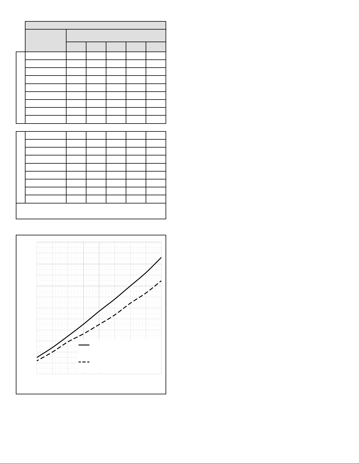
The outdoor fan is designed to operate against no more
than .10” w.c. static pressure.
Minimum and maximum operation conditions must be
observed to assure proper system performance. Refer to
Table 1 for the ambient operating limitations of the unit.
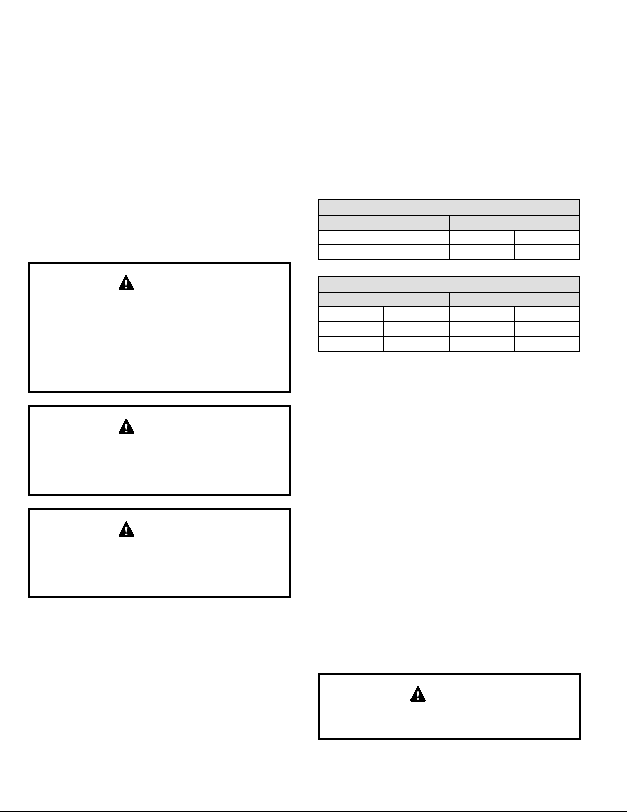
Table 1. Ambient Temperature Limitations
Outdoor Ambient Air Temperature °F
Minimum DB Maximum DB
Cool Cool Heat
65 115 75
Indoor Ambient Air Temperature °F
Minimum Maximum
DB/WB DB DB/WB DB
Cool Heat Cool Heat
62/57 50 90/72 80
DB = Dry Bulb
WB = Wet Bulb
Location
For information on wall sleeves and louver accessories,
see the Accessories section.
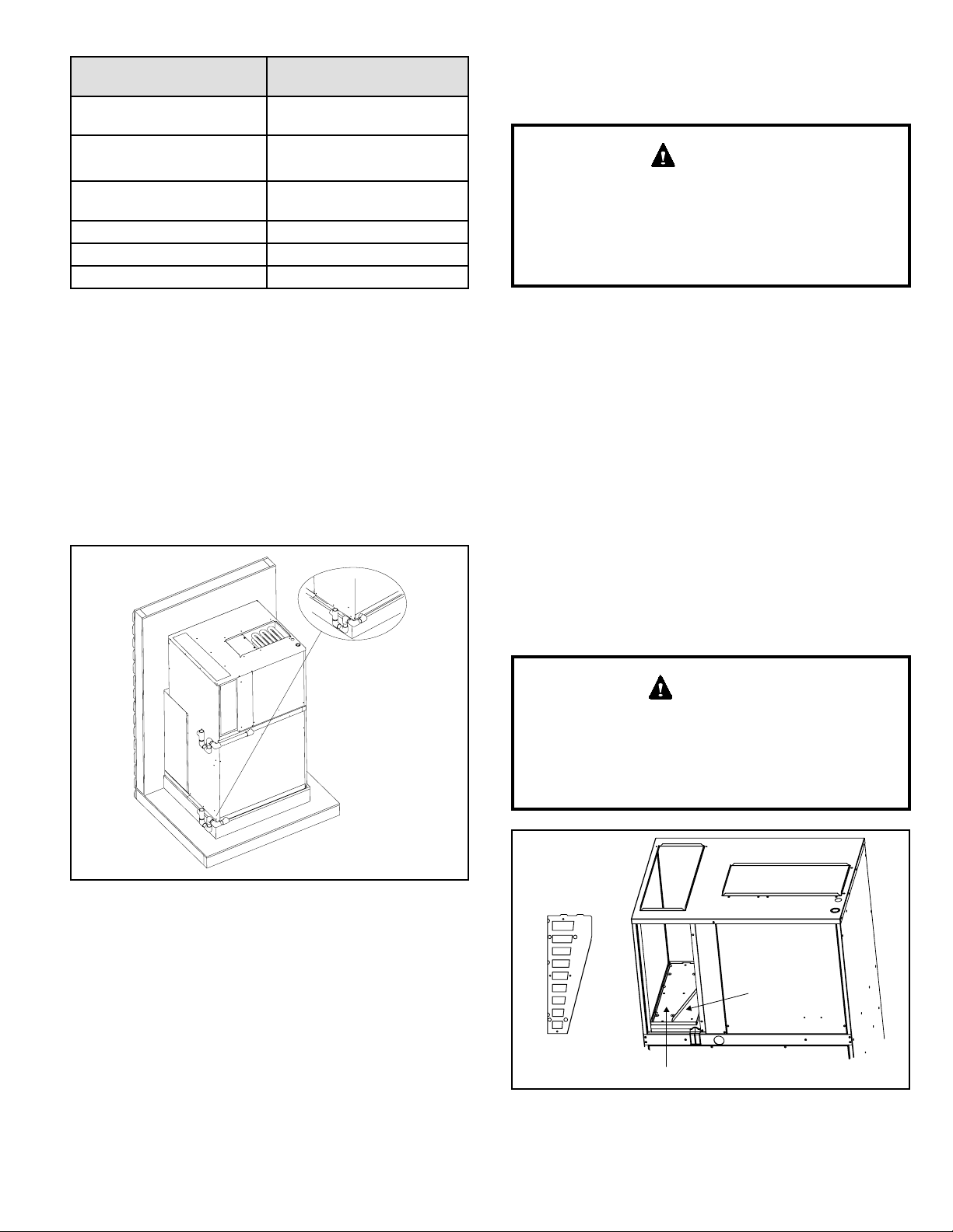
This unit is designed to be installed in up to the wall (exterior
wall) installation only. Refer to Figure 2 for additional
details. Accessibility clearances must take precedence
over re protection clearances.
The outside of the unit may be ush with the face of
the exterior wall, and it should not be obstructed with
trees, landscape materials, or building structure. Unit
can be installed recessed with appropriate wall sleeve
accessories. There is no minimum clearance required on
locating the unit to an interior corner of a building.
If the unit is installed in a residential garage, it must be
located or protected to avoid physical damage by vehicles.
The unit must be installed so that no electrical components
are exposed to water.
This unit must be installed level to allow for proper
drainage of the unit base pan and indoor drain pan.
CAUTION

508196-01 Issue 2120 Page 3 of 18
Unit Dimensions (in.)
Model A B* C D E F G H J K L M N
*MHP4-12-091*P
*MHP4-12-121*P 43-7/8 16-7/8 25-1/4 21-1/2 18-5/8 19-1/4 6 8 16 17-1/16 3/4 2-1/4 24-5/8
*MHP4-12-181*P 47-7/8 18-7/8 27-1/4 21-1/2 20-5/8 21-1/4 6 8 16 19-1/16 3/4 2-1/4 26-5/8
*MHP4-12-241*P 55-7/8 22-7/8 31-1/4 24-3/8 24-5/8 25-1/4 6 8 16 22-7/16 3/4 1 30-5/8
*MHP4-12-301*P 55-7/8 22-7/8 31-1/4 24-3/8 24-5/8 25-1/4 6 11-3/8 10-7/16 22-7/16 3-3/4 1 30-5/8
*MHP4-14-361*P 67-7/8 26-7/8 35-1/4 24-3/8 28-5/8 29-1/4 10 11-3/8 10-7/16 22-7/16 3-3/4 1 38-5/8
* Dimension B represents the height of the optional front return air duct opening
J
Return Air
Opening
K
M
Thermostat
Wiring
Connections
Line Voltage
Knockouts
(7/8 and 1-1/8 Dia.)
Top View
3/4”
H
2-1/4”
5”
Supply Air
Opening
1”
6-1/16”
28”
H
6-1/8”
Side View
D
A
N
Outdoor Fan Discharge
Outdoor
Coil
F
G
E
Rear View
Return Air
Opening
Supply Air
Opening
Ventilation
Air Chase
Secondary Condensate
Drain Pan 3/4” NPT*
Primary Condensate
Drain Pan 3/4” NPT*
Tool-less
Filter Access
Supply Air
Opening
Indoor
Blower /
Controls
Access
Optional
Front
Return Air
Opening
Compressor / Gauge Ports /
Outdoor Fan Access
Front View
J
C
B
L
10-5/8”
5/8”
2” 28”
Return Air
Opening
7-3/4”
1”
* Provisions must be made to properly drain condensate from the primary and secondary drain pans.
Figure 1.

Page 4 of 18 508196-01Issue 2120
Unit must be supported by platform, which must be
level with sill plate of opening in exterior wall.
Platform (field supplied) -
Supply Duct
Opening
Clearance to
Front of Unit
Optional Front
Return Opening
May be used with
or without
ductwork attached
Top Return
Opening
1” Min.
Side Clearance
Exterior Wall
Closet Wall
Closet Wall
1” Min.
Side Clearance
Closet Door / Access
Panel Opening
Minimum 30” wide
Top View
ExteriorWall
Wall Sleeve
Side Panel
(one each side)
InteriorWall
Minimum
Clearance
3/4" Plywood Riser
(supplied with wall sleeve)
Floor
Front of Unit
Sill Plate
4" Min.
Supply
Duct
Mounting Strap
(one each side;
supplied with unit)
Return
Duct
Primary
Condensate
Drain Trap
(field supplied)
Secondary
Condensate
Drain Trap
(field supplied)
Side View
IMPORTANT
The unit must be installed with approved wall sleeve
and louver accessories for safe operation. Improper
installations could result in property damage,
personal injury, or death.
Accessibility Clearances
The front of the unit must be accessible for service. A
minimum clearance of 30” in front of unit is required for
service.
If the unit is enclosed, a door or access panel aligned with
the front of the unit is the preferred method of providing
access. The door or access panel opening must be a
minimum of 30” wide (centered on the unit) and be as
tall as the unit.
Supply Duct Clearances
Minimum Clearances to Combustible
Materials1
Front Sides Top
0” 0” 0”
1 Accessibility clearances take precedence
Unit Clearances Minimum
Clearances1
Return Duct
Conguration Unit Height Front Sides³
Ducted Top
Opening All Note 2 1”
Ducted Front
Opening5All Notes
2 & 4 1”
Non-Ducted/
Free Return
43” 4” 1”
48” - 68” 5” 1”
1 Accessibility clearances take precedence
2 Clearance must accommodate eld-installed
condensate drain line / drain trap
3 Additional clearance required if eld-installed
condensate drain line/drain trap is routed alongside
unit
4 Consult local codes for other clearance
requirements
5 If ductwork is attached to the optional front return
opening, provisions to service unit lter must be
provided
Figure 2. Minimum Clearances

508196-01 Issue 2120 Page 5 of 18
Wall Sleeve and Louver Installation
Refer to installation instructions included with the wall
sleeve kit and the louver kit along with Figure 3 for guidance
in assembling and installing the wall sleeve and louver.
The sleeve is not intended as the sole support for
the unit. An additional support must be provided for
adequate support (see Figure 3).
CAUTION
Installing and Securing Unit to Wall Sleeve
1. Before installing and securing the unit to the wall
sleeve, make sure that the proper louver is installed.
2. Make sure the gaskets attached to the sleeve are not
damaged.
3. Verify divider panel is positioned properly. Refer to
Table 2 for wall sleeves that allow for multiple divider
panel locations.
Model
ASLEEVE**-2 ASLEEVE**-5 Orientation
of Flange
Two
Positions
Three
Positions
MHP4-12-09,12 Lower Lower Down
MHP4-12-18
UpMHP4-12-24, 30 Upper Middle
MHP4-14-36 N/A Upper
Table 2.
4. Place the unit into the wall sleeve. Lift leading end
of unit and walk unit onto the sleeve. Once in the
wall sleeve, lower the unit into position. This prevents
damage to the base pads. Assure that the unit is level
and completely seated against the gaskets on the wall
sleeve. The unit must be supported by a eld supplied
base platform.
Figure 3. Wall Sleeve and Louver Kit Installation
NOTE: Unit must be supported by platform, which must be level with sill plate of opening in exterior wall.
Exterior Wall
Wall Sleeve Top Panel
Wall Sleeve Side Panel
Platform
(field fabricated
and supplied)
Platform Height: Minimum 4”
3/4” Board Added to
Level Platform with
Wall Sleeve Base
(provided with
wall Sleeve)
Lag Screws with Washers
Wall Sleeve Base
Wall Sleeve Side Panel
Wall Sleeve Divider Panel

Page 6 of 18 508196-01Issue 2120
Figure 4. Positioning Divider Panel
Flange Up Orientation
Flange Down Orientation
5. Use the two installation brackets to secure the unit to
the wall sleeve (see Figure 5). The units are shipped
with the brackets placed in the return air compartment.
Hook each bracket into the front edge of the wall sleeve
side. Position the bracket so it can be bent around the
front corner of the unit. Remove one of the two screws
in that position on the unit. Line up one of the holes in
the installation bracket with the screw hole and attach
the bracket to the unit with that screw. Make sure to
fasten tight enough that the seal is maintained. Trim
o excess bracket if applicable.
Figure 5. Securing Unit
Installation
Brackets
Remove and replace screw to secure bracket
(one each side)
Do not screw into the side of the drain pan, the indoor coil
or the heat strip, which is located above the installation
bracket.
CAUTION
6. Inspect the t up of the unit to the wall sleeve. Verify
that the gaskets of the wall sleeve make a complete
seal to the unit paying particular attention to top and
bottom corners of unit to sleeve seal. Caulk if needed.
Ductwork
Ductwork should be designed and sized according to the
methods in Manual Q of the Air Conditioning Contractors
of America (ACCA).
Check unit supply and return air outlets for debris
before making ductwork connections.
It is recommended that supply and return duct connections
at the unit be made with exible joints. If exible ducts are
used, a 6” sheet metal starter collar is required.
The supply and return air duct systems should be fabricated
per the designed CFM and static requirements of the job
(see Table 3). Ductwork should not be sized to match
the dimensions of the duct connections on the unit.
The return duct should be sealed to the unit casing and
terminate outside the space containing the unit.
Optional Front Return
As shipped, units are congured for attaching supply and
return ductwork to the top of the unit. Return air may be
brought in through the optional front return opening. To
open the optional front return and close o the top return
opening, perform the following steps.
1. Rotate knob to release lter access panel and remove
panel.
a. For all units except 3-ton models, position lter
access panel to close o top return opening.
Secure at rear using two sheet metal screws.
Secure in front using knob. See Figure 6.
b. For 3-ton models, eld fabricate a sheet metal
panel to close o the top return opening.
2. Seal panel to top of unit with tape or mastic.
NOTE: If ductwork is attached to the optional front return
opening, provisions to service unit lter must be provided.
Filter may need to be relocated to a suitable location
outside the cabinet for ease of service.
Figure 6. Secure Filter Access Panel

508196-01 Issue 2120 Page 7 of 18
Airow Performance as a Function of External Static Pressure
Model
Indoor Blower Speed
0.1 “w.c. 0.2 “w.c. 0.3 “w.c. 0.4 “w.c. 0.5 “w.c.
SCFM Watts HP SCFM Watts HP SCFM Watts HP SCFM Watts HP SCFM Watts HP
*MHP4-12-091*P
TAP 1 (FAN) 365 28 0.04 330 31 0.04 275 35 0.05 225 38 0.05 180 41 0.05
TAP 2 (COOL/HP)†375 28 0.04 325 32 0.04 275 35 0.05 N/A N/A N/A N/A N/A N/A
TAP 3 (COOL/HP) N/A N/A N/A N/A N/A N/A 395 54 0.07 370 58 0.08 330 62 0.08
3 kW
TAP 4 (AUX HEAT)* 515 55 0.07 485 58 0.08 450 62 0.08 N/A N/A N/A N/A N/A N/A
TAP 5 (AUX HEAT) 600 73 0.10 570 78 0.10 545 84 0.11 515 88 0.12 475 92 0.12
5 kW
TAP 4 (AUX HEAT)* 570 69 0.09 545 73 0.10 515 77 0.10 N/A N/A N/A N/A N/A N/A
TAP 5 (AUX HEAT) 660 92 0.12 635 98 0.13 605 104 0.14 580 109 0.15 550 114 0.15
*MHP4-12-121*P
TAP 1 (FAN) 365 28 0.04 330 31 0.04 275 35 0.05 225 38 0.05 180 41 0.05
TAP 2 (COOL/HP)†490 50 0.07 460 55 0.07 420 59 0.08 N/A N/A N/A N/A N/A N/A
TAP 3 (COOL/HP) N/A N/A N/A 555 77 0.10 525 82 0.11 495 86 0.12 460 91 0.12
3 kW
TAP 4 (AUX HEAT)* 515 55 0.07 485 58 0.08 450 62 0.08 N/A N/A N/A N/A N/A N/A
TAP 5 (AUX HEAT) 600 73 0.10 570 78 0.10 545 84 0.11 515 88 0.12 475 92 0.12
5 kW
TAP 4 (AUX HEAT)* 570 69 0.09 545 73 0.10 515 77 0.10 N/A N/A N/A N/A N/A N/A
TAP 5 (AUX HEAT) 660 92 0.12 635 98 0.13 605 104 0.14 580 109 0.15 550 114 0.15
*MHP4-12-181*P
TAP 1 (FAN) 365 32 0.04 335 35 0.05 280 39 0.05 235 42 0.06 175 46 0.06
TAP 2 (COOL/HP)†615 103 0.14 590 108 0.14 555 112 0.15 530 117 0.16 500 121 0.16
TAP 3 (COOL/HP) 700 135 0.18 670 141 0.19 640 146 0.20 615 151 0.20 590 157 0.21
3 kW
TAP 4 (AUX HEAT)* 615 93 0.12 590 97 0.13 555 101 0.14 N/A N/A N/A N/A N/A N/A
TAP 5 (AUX HEAT) 715 127 0.17 685 134 0.18 655 140 0.19 630 146 0.20 600 151 0.20
5 kW
TAP 4 (AUX HEAT)* 665 110 0.15 635 114 0.15 605 118 0.16 N/A N/A N/A N/A N/A N/A
TAP 5 (AUX HEAT) 750 148 0.20 725 154 0.21 700 160 0.21 675 166 0.22 650 171 0.23
7 kW
TAP 4 (AUX HEAT)* 725 137 0.18 705 144 0.19 675 150 0.20 N/A N/A N/A N/A N/A N/A
TAP 5 (AUX HEAT) N/A N/A N/A 800 200 0.27 780 205 0.27 755 209 0.28 725 213 0.29
10 kW
TAP 4 (AUX HEAT)* 750 148 0.20 725 154 0.21 700 161 0.22 N/A N/A N/A N/A N/A N/A
TAP 5 (AUX HEAT) N/A N/A N/A N/A N/A N/A 805 224 0.30 780 228 0.31 750 232 0.31
*MHP4-12-241*P
TAP 1 (FAN) 460 43 0.06 420 47 0.06 380 51 0.07 350 54 0.07 290 59 0.08
TAP 2 (COOL/HP)†815 150 0.20 785 161 0.22 760 165 0.22 740 172 0.23 715 178 0.24
TAP 3 (COOL/HP) 885 201 0.27 860 208 0.28 835 213 0.29 805 217 0.29 785 220 0.30
5 kW
TAP 4 (AUX HEAT)* 800 146 0.20 775 152 0.20 750 157 0.21 N/A N/A N/A N/A N/A N/A
TAP 5 (AUX HEAT) 905 201 0.27 880 207 0.28 855 212 0.28 825 216 0.29 800 219 0.29
7 kW
TAP 4 (AUX HEAT)* 855 174 0.23 830 179 0.24 800 183 0.25 N/A N/A N/A N/A N/A N/A
TAP 5 (AUX HEAT) N/A N/A N/A 930 231 0.31 900 235 0.32 875 239 0.32 850 243 0.33
10 kW
TAP 4 (AUX HEAT)* 855 174 0.23 830 179 0.24 800 183 0.25 N/A N/A N/A N/A N/A N/A
TAP 5 (AUX HEAT) N/A N/A N/A 930 231 0.31 900 235 0.32 875 239 0.32 850 243 0.33
N/A: Do not operate unit using this blower speed at this external static pressure.
† As shipped speed for Cooling operation. Blower speed must be eld adjusted to Speed Tap 3 for higher duct static applications.
* As shipped speed for Heating operation. Blower speed must be eld adjusted to Speed Tap 5 for higher duct static applications.
Table 3. Blower Performance (208V or 230V)

Page 8 of 18 508196-01Issue 2120
Airow Performance as a Function of External Static Pressure
Model
Indoor Blower Speed
0.1 “w.c. 0.2 “w.c. 0.3 “w.c. 0.4 “w.c. 0.5 “w.c.
SCFM Watts HP SCFM Watts HP SCFM Watts HP SCFM Watts HP SCFM Watts HP
*MHP4-12-301*P
TAP 1 (FAN) 590 43 0.06 535 48 0.06 430 55 0.07 380 60 0.08 315 65 0.09
TAP 2 (COOL/HP)†1040 161 0.22 1005 169 0.23 970 177 0.24 935 185 0.25 900 193 0.26
TAP 3 (COOL/HP) N/A N/A N/A 1105 211 0.28 1070 220 0.30 1040 229 0.31 1010 237 0.32
5 kW
TAP 4 (AUX HEAT)* 1075 151 0.20 1040 159 0.21 1005 168 0.23 N/A N/A N/A N/A N/A N/A
TAP 5 (AUX HEAT) N/A N/A N/A N/A N/A N/A 1100 205 0.27 1065 216 0.29 1025 225 0.30
7 kW
TAP 4 (AUX HEAT)* 1075 151 0.20 1040 159 0.21 1005 168 0.23 N/A N/A N/A N/A N/A N/A
TAP 5 (AUX HEAT) N/A N/A N/A N/A N/A N/A 1100 205 0.27 1065 216 0.29 1025 225 0.30
10 kW
TAP 4 (AUX HEAT)* 1075 151 0.20 1040 159 0.21 1005 168 0.23 N/A N/A N/A N/A N/A N/A
TAP 5 (AUX HEAT) N/A N/A N/A N/A N/A N/A 1100 205 0.27 1065 216 0.29 1025 225 0.30
*MHP4-14-361*P
TAP 1 (FAN) 680 61 0.08 630 68 0.09 575 74 0.10 525 79 0.11 460 86 0.12
TAP 2 (COOL/HP)†1235 260 0.35 1200 272 0.36 1165 284 0.38 1135 295 0.40 1100 305 0.41
TAP 3 (COOL/HP) N/A N/A N/A N/A N/A N/A 1250 330 0.44 1215 342 0.46 1180 354 0.47
5 kW
TAP 4 (AUX HEAT)* 1240 232 0.31 1205 248 0.33 1170 262 0.35 N/A N/A N/A N/A N/A N/A
TAP 5 (AUX HEAT) N/A N/A N/A N/A N/A N/A 1260 315 0.42 1230 328 0.44 1200 338 0.45
7 kW
TAP 4 (AUX HEAT)* 1240 232 0.31 1205 248 0.33 1170 262 0.35 N/A N/A N/A N/A N/A N/A
TAP 5 (AUX HEAT) N/A N/A N/A N/A N/A N/A 1260 315 0.42 1230 328 0.44 1200 338 0.45
10 kW
TAP 4 (AUX HEAT)* 1240 232 0.31 1205 248 0.33 1170 262 0.35 N/A N/A N/A N/A N/A N/A
TAP 5 (AUX HEAT) N/A N/A N/A N/A N/A N/A 1260 315 0.42 1230 328 0.44 1200 338 0.45
N/A: Do not operate unit using this blower speed at this external static pressure.
† As shipped speed for Cooling operation. Blower speed must be eld adjusted to Speed Tap 3 for higher duct static applications.
* As shipped speed for Heating operation. Blower speed must be eld adjusted to Speed Tap 5 for higher duct static applications.
Table 3. Blower Performance (208V or 230V)
Filter
All return air must be ltered. A washable lter is furnished
with the unit, located in the return air compartment. If the
optional front return opening is used and a duct is installed,
provisions must be made to accommodate lter servicing. If
a lter is installed at a separate central return location,
then the factory furnished lter must be removed from
the unit.
The washable lter may be replaced with a disposable
lter. Avoid lter with paper frame and media; if it gets wet,
it could collapse and block the coil, restricting airow and
causing issues with unit operation. Table 4 lists lter sizes
that t the unit.
When proper duct design is applied, eld-provided lters
up to MERV 6 can typically be installed in the unit’s factory
lter location in lieu of a washable lter. If a higher resistance
lter is eld installed in the unit, the added resistance must
be included in the external static pressure and must not
exceed 0.5 in. w.c., including ductwork.
If an installation is made in which it is more desirable to
mount the lter exterior to the unit, in the return duct work
or elsewhere, the washable lter can be used or replaced
with a disposable lter. If a disposable lter is used, in lieu
of washable lter, use the information provided in Table 5
when sizing the disposable lter.
Model Number Filter Size
(in.)
*MHP4-12-09*
*MHP4-12-12* 18 x 20 x 1
*MHP4-12-18* 20 x 20 x 1
*MHP4-12-24*
*MHP4-12-30* 22 x 24 x 1
*MHP4-14-36* 22 x 28 x 1
Table 4. Filter Sizes

508196-01 Issue 2120 Page 9 of 18
Model Number Filter Area
(in2)
*MHP4-12-09*
*MHP4-12-12* 265
3MHP4-12-18*
5MHP4-12-18* 310
7MHP4-12-18*
10MHP4-12-18* 360
*MHP4-12-24* 400
*MHP4-12-30* 515
*MHP4-14-36* 600
Table 5. Minimum Required Surface Area for
Disposable Filters
Condensate Drain
Provisions must be made to properly drain the primary and
secondary drain pans of this appliance.
Primary drain and secondary drain connection: 3/4” NPT to
3/4” PVC tting (schedule 40 minimum). Both drains must
be trapped as shown in Figure 7. The drain line should
pitch gradually downward at least 1” per 10’ of horizontal
run to an open drain.
Figure 7. Condensate Drain Installation
If local codes require the use of metal condensate lines,
do not thread metal ttings into the unit drain pans. Thread
a PVC tting into the unit drain pans and make the eld
connection to the PVC tting.
NOTE: These units are designed with a redundant drain
system to handle condensate without the need for an
emergency drain pan. Should the indoor coil condensate
drain system fail, all water is contained within the unit and
the ow is directed into the unit base pan. From there it
will drain into the condensate riser. If for some reason the
water cannot drain into the main condensate riser, all water
is contained in the unit, and the design will allow drainage
out through the wall sleeve and louver to the outside of the
building.
Use thread sealant on the threaded ttings. Install
threaded ttings by hand only. Do not over torque the
ttings.
Do not thread metal condensate ttings to unit drain
pans.
CAUTION
Ventilation Air
Units ship with a panel installed that seals the return air
compartment at the ventilation air intake. Installers can
choose to remove the factory-installed panel and use
the eld-provided ventilation damper if introduction of
ventilation air is desired.
NOTE: If ventilation air is introduced, the quantity of air
and conditions of this air must be accounted for in the load
calculations.
The auxiliary panel has nine knockouts to congure
ventilation air ow to installation requirements. Use Table
6 and Figure 8 to determine which knockouts to remove
from the auxiliary panel in order to achieve the desired
ventilation air ow. Use a at head screw driver to remove
the knockouts. Set the factory-installed panel aside for
possible future changes.
The location of ventilation air capable models must
conform to the requirements of National Fire Protection
Association NFPA No. 54 in regards to proximity
of forced air inlets to ue gas terminals. Improper
installation could result in personal injury or death.
WARNING
Figure 8. Auxiliary and Factory Panel for Ventilation
Air
Factory panel
Ventilation
Air Duct
Auxillary panel
with knockouts
1
2
3
4
5
6
7
8
9

Page 10 of 18 508196-01Issue 2120
Ventilation Air (CFM) *
Cumulative
Knockouts
Removed
Total External Static Pressure
(supply + return) **
0.1 0.2 0.3 0.4 0.5
0.75, 1.0, 1.5 TON
# 1 Only 7 9 12 15 18
#1 thru #2 10 15 20 24 28
#1 thru #3 12 18 25 32 38
#1 thru #4 18 28 36 45 54
#1 thru #5 23 35 46 57 69
#1 thru #6 27 41 54 67 80
#1 thru #7 32 48 63 78 93
#1 thru #8 37 55 73 90 107
#1 thru #9 41 61 80 100 118
2.0, 2.5, 3.0 TON
# 1 Only 21 20 19 17 16
#1 thru #2 28 27 25 24 22
#1 thru #3 35 33 32 30 28
#1 thru #4 45 42 40 38 35
#1 thru #5 55 52 49 46 43
#1 thru #6 66 62 59 55 52
#1 thru #7 79 75 71 66 62
#1 thru #8 91 86 81 76 71
#1 thru #9 105 99 94 88 82
* Assumes proper speed tap adjustments to maintain nominal supply air CFM
** Assumes equal supply and return static pressures
Table 6.
Ventilation Air (CFM)
Cumulative Knockouts Removed
0
10
20
30
40
50
60
70
80
90
100
110
120
123456789
0.75, 1, 1.5 Ton .225'' Supply & .225''
Return, .45'' Total Duct Static
2, 2.5, 3 Ton .225'' Supply & .225''
Return, .45'' Total Duct Static
Figure 9. Ventilation Air CFM
Thermostat
The room thermostat should be located on an inside
wall where it will not be subject to drafts, sun exposure,
or heat from electrical xtures or appliances. Follow
manufacturer’s instructions enclosed with the thermostat
for general installation procedures. Color-coded insulated
wires (#18 AWG) should be used to connect the thermostat
to the unit.
Electrical Connections
The unit must be electrically grounded in accordance with
local codes or, in the absence of local codes, with the
National Electrical Code ANSI/NFPA No. 70 (latest edition)
or CSA C22.2 Part 1 (latest edition). Any alteration of
internal wiring will void certication and warranty.
Units are factory wired for a 230 volt power supply. If power
supply is 208 volts, it will be necessary to change a wire
connection on unit transformer from 240 volt terminal to
208 volt terminal as shown on the wiring diagram.
Use wiring with a temperature limitation of 75°F minimum.
Run the 208 or 230 volt, single phase, 60 hertz electric
power supply through a fused disconnect switch to the
control box of the unit and connect as shown in the unit’s
wiring diagram.
The power supply to the unit must be NEC Class 1 and
must comply with all applicable codes. A fused disconnect
switch should be eld provided for the unit, and must be
separate from all other circuits. If any of the wire supplied
with the unit must be replaced, replacement wire must be
of the type shown on the wiring diagram.
Electrical wiring must be sized to minimum circuit ampacity
(MCA) marked on the unit. Use copper conductors only.
Each unit must be wired with a separate branch circuit and
be properly fused.
NOTE: Some models require two separate power supply
circuits. See the unit wiring diagrams and rating plates for
specications.

508196-01 Issue 2120 Page 11 of 18
Operation
Sequence of Operation
Upon initial “power up” to unit, there is a 3-minute time delay
to the compressor contactor (R to Y). Any 24V interrupt (R,
C) to the defrost control will initiate the 3-minute delay to
the contactor.
Cooling
When the thermostat is in the cooling mode, the O circuit
is powered which energizes the reversing valve. Upon
cooling demand, the thermostat closes circuit R to Y and
G. Closing R to Y closes the unit contactor, starting the
compressor and outdoor fan, and signaling the indoor
blower to run at cooling speed. Upon satisfying cooling
demand, the thermostat will open the above circuits and
open the main contactor, stopping the compressor and
outdoor fan. The unit is equipped with a blower OFF delay;
the blower will continue to operate for a xed 90 seconds
after the thermostat is satised.
Heating
Upon heating demand, the thermostat closes circuit R to
Y, which closes the unit contactor, starting the compressor
and outdoor fan. The reversing valve is not energized in
the heating mode. The Y signal from the thermostat brings
the indoor blower on at heat pump speed. The second
stage of the thermostat closes circuit R to W, which closes
the unit sequencers, bringing the auxiliary electric heat on.
The W signal from the thermostat brings the indoor blower
on at electric heat speed. Upon satisfying heating demand,
the thermostat opens the above circuits and stops unit
operation.
The unit is equipped with a blower OFF delay; the blower
will continue to operate for a xed 90 seconds (heat pump)
or 120 seconds (electric heat) after the thermostat is
satised.
NOTE: The 7.2 and 10 kW heats strips oer a W1 and
W2 thermostat connection. Taking advantage of the two
heat strip circuits requires a 3-stage thermostat (Y for heat
pump, W1 for electric heat stage 1, and W2 for electric
heat stage 2). If a 2-stage thermostat is used, “pigtail” W1
and W2 wires together when connecting the thermostat
wires at the unit.
Defrost Cycle
If the outdoor ambient conditions are such that frost forms
on the outdoor coil, the defrost control monitors the need
for, initiates, and terminates defrost cycles as necessary to
maintain system performance.
The defrost control is time/temperature initiated and
temperature terminated with a maximum defrost time
(time-out) of 14 minutes. The time between defrost cycles
is preset at 90-minute intervals at the factory, but can be
eld adjusted to 30 or 60 minutes. To eld adjust time
between defrost cycles, place defrost time plug in the
proper position (see Figure 11).
Figure 10. Defrost Control
24V TERMINAL
STRIP
CONNECTIONS
DIAGNOSTIC
LEDS
HIGH PRESSURE
SWITCH
TEST
PINS
REVERSING
VALVE
DEFROST
THERMOSTAT
LOW PRESSURE
SWITCH SERVICE LIGHT
CONNECTIONS
FIELD SELECT
DEFROST INTERVAL
TIMING PINS
30
TEST
90
60
P1
Figure 11. Defrost Interval Timing Jumper
Defrost control will initiate a defrost cycle if the time period
has elapsed and the defrost sensor sees a temperature
below freezing. At the start of a defrost cycle, the defrost
control will energize the reversing valve solenoid, shifting
the reversing valve and de-energizing the outdoor fan.
The defrost control will also energize auxiliary heat for
increased comfort during defrost. The unit will remain in
defrost until the defrost sensor has determined that the
frost has been removed from the coil or a 14-minute time
period has elapsed.

Page 12 of 18 508196-01Issue 2120
Maintenance
Disconnect all electrical power to the unit before
conducting any maintenance procedures. Failure to
disconnect the power could result in personal injury or
death.
WARNING
The refrigeration system normally requires no maintenance
since it is a closed, self-contained system.
Periodic inspection and maintenance normally consists of
changing or cleaning lters and (under some conditions)
cleaning the coils.
Filter
Inspect the lter once a month. Replace disposable lter or
clean the washable lter as necessary (a minimum of three
times each heating or cooling season is recommended).
To clean the washable lter, shake lter to remove excess
dirt and/or use a vacuum cleaner. Wash lter in soap or
detergent water and replace after lter is dry.
Motors
The indoor and outdoor fan motors are permanently
lubricated and require no maintenance.
Outdoor Coil
Foreign material should not be allowed to accumulate on
the outdoor coil surface or other parts in the air circuit.
Cleaning should be as often as necessary to keep the coil
clean. To clean the coil, remove the lower access panel
and blow out debris by using compressed air or water. Be
sure power to unit is shut o before using water to
clean the coil.
Care should be used when cleaning the coils so that
the coil ns are not damaged.
Primary and Secondary Condensate Drain
Foreign material should not be allowed to clog the drain
hole. Inspect and clear drain opening prior to each heating
and cooling season.
The defrost control is also equipped with a set of pins to
aid in the troubleshooting of the defrost system (see Figure
11). The following is a brief outline of the testing of the
defrost system.
1. Defrost sensor must be closed, 32°F or below. If
temperatures are such that the switch will not close,
jumper between defrost sensor terminals on the
defrost control.
2. Start system in heating operation.
3. Place the defrost pin jumper on the test pins for a brief
second, then place back on the proper defrost time
setting (30, 60, or 90). This will speed up defrost time
interval as shown in Table 7.
Defrost Control Setting Defrost Test Cycle Time
30 minutes 7 seconds
60 minutes 14 seconds
90 minutes 21 seconds
Table 7. Defrost Test Cycle Time
The reversing valve will then shift to defrost mode and
the outdoor fan should stop. After 2 seconds of defrost
operation, the reversing valve should shift back to heating
operation and the outdoor fan should start.
Diagnostic LEDs
The state (O, On, Flashing) of two LEDs on the defrost
board (DS1 [Red] and DS2 [Green]) indicate diagnostics
conditions that are described in Table 8.
Mode Green LED (DS2) Red LED (DS1)
No power to control O O
Normal operation /
power to control Simultaneous slow ash
Timed lockout Alternating slow ash
Low pressure switch
fault O Slow ash
Low pressure switch
lockout O On
High pressure switch
fault Slow ash O
High pressure switch
lockout On O
Table 8.

508196-01 Issue 2120 Page 13 of 18
Accessories
The unit must be installed with approved wall sleeve and louver accessories for safe operation. Improper installations
could result in property damage, personal injury, or death.
WARNING
Refer to Table 9 for dimension information.
B
29-1/8
Required Wall Opening
C
Maximum Wall
Thickness
Exterior Wall
16
A
16-5/8
29
Wall Sleeve
Figure 12.

Page 14 of 18 508196-01Issue 2120
Wall Sleeves Louvers Model
Dimensions (in.)
Wall
Sleeve Wall Opening
Wall Sleeve Wall Sleeve
Extension
Polypropylene
Louvers
Aluminum
Louvers
Impact
Louvers
*MHP4-12-091*P
*MHP4-12-121*P
*MHP4-12-181*P
*MHP4-12-241*P
*MHP4-12-301*P
*MHP4-14-361*P
Height
(A)
Height
(B)
Depth
(C)
Sleeve
Only
Sleeve
Plus
Extension
ASLEEVE6-1 --- ALVRP***-1 ALVRAL-1^ ALVRALC-1^ ••• 29 29-1/8 6 ---
ASLEEVE8-1 --- ALVRP***-1 ALVRAL-1^ ALVRALC-1^ ••• 29 29-1/8 8 ---
ASLEEVE10-1 ASLEEVEXT4-1 ALVRP***-1 ALVRAL-1^ ALVRALC-1^ ••• 29 29-1/8 10 14
ASLEEVE12-1 ASLEEVEXT4-1 ALVRP***-1 ALVRAL-1^ ALVRALC-1^ ••• 29 29-1/8 12 16
ASLEEVE6-2 --- ALVRP***-2 ALVRAL-2^ ALVRALC-2^ • • 32-3/4 32-7/8 6 ---
ASLEEVE8-2 --- ALVRP***-2 ALVRAL-2^ ALVRALC-2^ • • 32-3/4 32-7/8 8 ---
ASLEEVE10-2 ASLEEVEXT4-2 ALVRP***-2 ALVRAL-2^ ALVRALC-2^ • • 32-3/4 32-7/8 10 14
ASLEEVE12-2 ASLEEVEXT4-2 ALVRP***-2 ALVRAL-2^ ALVRALC-2^ • • 32-3/4 32-7/8 12 16
ASLEEVE6-2 --- ALVRP***-2 ALVRAL-7^ ○○○ 32-3/4 32-7/8 6 ---
ASLEEVE8-2 --- ALVRP***-2 ALVRAL-7^ ○○○ 32-3/4 32-7/8 8 ---
ASLEEVE10-2 ASLEEVEXT4-2 ALVRP***-2 ALVRAL-7^ ○○○ 32-3/4 32-7/8 10 14
ASLEEVE12-2 ASLEEVEXT4-2 ALVRP***-2 ALVRAL-7^ ○○○ 32-3/4 32-7/8 12 16
ASLEEVE6-5 --- ALVRP***-3 --- --- ○○○○○•45 45-1/8 6 ---
ASLEEVE8-5 --- ALVRP***-3 --- --- ○○○○○•45 45-1/8 8 ---
ASLEEVE10-5 ASLEEVEXT4-3 ALVRP***-3 --- --- ○○○○○•45 45-1/8 10 14
ASLEEVE12-5 ASLEEVEXT4-3 ALVRP***-3 --- --- ○○○○○•45 45-1/8 12 16
ASLEEVE6-5 --- --- ALVRAL-3^ ALVRALC-3^ ○○○ 45 45-1/8 6 ---
ASLEEVE8-5 --- --- ALVRAL-3^ ALVRALC-3^ ○○○ 45 45-1/8 8 ---
ASLEEVE10-5 ASLEEVEXT4-3 --- ALVRAL-3^ ALVRALC-3^ ○○○ 45 45-1/8 10 14
ASLEEVE12-5 ASLEEVEXT4-3 --- ALVRAL-3^ ALVRALC-3^ ○○○ 45 45-1/8 12 16
ASLEEVE6-5 --- --- ALVRAL-4^ ALVRALC-4^ ○ ○ •45 45-1/8 6 ---
ASLEEVE8-5 --- --- ALVRAL-4^ ALVRALC-4^ ○ ○ •45 45-1/8 8 ---
ASLEEVE10-5 ASLEEVEXT4-3 --- ALVRAL-4^ ALVRALC-4^ ○ ○ •45 45-1/8 10 14
ASLEEVE12-5 ASLEEVEXT4-3 --- ALVRAL-4^ ALVRALC-4^ ○ ○ •45 45-1/8 12 16
Note: Wall Sleeve and Louver size must be coordinated
*** Louver colors: WHT = white, SAN = sandstone, BGE = beige, TPST = taupestone
^ -P: Option to paint standard, aluminum, and impact-resistant louver
• Wall sleeve and louver sizes equal to the required wall opening dimensions for the unit size
◦ Optional: Wall sleeves and louvers can be oversized to maintain a uniform appearance
Table 9. Accessories

508196-01 Issue 2120 Page 15 of 18
Wiring Diagrams
Figure 13. Wiring Diagram - MHP with Single Circuit and Hard Start Enabled (0.75 Ton through 2.5 Ton)

Page 16 of 18 508196-01Issue 2120
Figure 14. Wiring Diagram - MHP with Dual Circuit and Hard Start Enabled (0.75 Ton through 2.5 Ton)

508196-01 Issue 2120 Page 17 of 18
Figure 15. Wiring Diagram - MHP with Single Circuit (3 Ton)

Page 18 of 18 508196-01Issue 2120
Figure 16. Wiring Diagram - MHP with Dual Circuit (3 Ton)
This manual suits for next models
7
Table of contents
Other Magic-Pak Heat Pump manuals
Popular Heat Pump manuals by other brands

Estia
Estia HWS-1501CSHM3-UK Installation and service manual

Dimplex
Dimplex SI 5CS Installation and operating instructions

Calorex
Calorex AW631 Owners & installation manual

Bryant
Bryant Evolution 284ANV Series manual

Carrier
Carrier 38YRA Installation and start-up instructions

evoheat
evoheat EVO ULTRA 32 Installation & operation manual

Nibe
Nibe VVM 500 Installer manual

York
York F3EH090 installation manual

Dimplex
Dimplex LA 17TU Installation and operating instructions

Panasonic
Panasonic WH-UDZ03KE5 installation manual

Viessmann
Viessmann Vitocal 350-G Installation and service instructions for contractors

Sanyo
Sanyo KHS0922 instruction manual