Magikist VS0 User manual

Stainless steel
Vacuum
Instruction Manual
v1.2
VS0 Free Standing Indoor
or Outdoor Vacuum
Thank you for purchasing a Magikist vacuum. Magikist vacuums are designed for ease of
installation, operation, and maintenance. They are built ruggedly of stainless steel for years of
use. Please read this manual fully before installing and operating your vacuum. Should you still have
questions regarding your vacuum, please contact your supplier who can provide you with the answers
you require.
VS0-CP Model shown
For future reference, record the model and serial number located near the bottom of the vacuum
body. In addition, if your vacuum has a lockable coin meter, please record the key numbers for both
the upper portion and the money drawer of the coin meter. The key numbers are stamped on the
keys.
Model# ___________________________________!
Serial# ____________________________________________!
Key Numbers ____________________________________________

IMPORTANT SAFETY INSTRUCTIONS
READ ALL INSTRUCTIONS BEFORE USING THIS APPLIANCE.
• All local and national electric codes must be followed for installation and use. Licensed
electricians are recommended for installation.
• The vacuum must be connected to a grounded metal, permanent wiring system; or an
equipment-grounding conductor must be run with the circuit conductors and connected to
the equipment-grounding terminal or lead on the appliance.
• High voltage is present in the coin meter and under the top dome of the vacuum. Always
disconnect power before performing service work inside the coin meter or the top dome of
the vacuum.
• This equipment incorporates switches, motors, or similar parts that can produce arcs or
sparks. When installed in a service station or other gasoline dispensing locations, install this
appliance a minimum of 20 feet (6 meters) horizontally from the exterior enclosure of any
dispensing pump and a minimum of 18 inches (45 centimeters) above ground level.
• Use only as described in manual with manufacturer approved parts and accessories.
• Keep hair, loose clothing, fingers, and all parts of body away from openings and moving
parts.
• Do not use to pick up flammable or combustible liquids, such as gasoline, or use in areas
where they may be present. Do not pick up anything that is burning or smoking, such as
cigarettes, matches, or hot ashes.
• Do not use without filter bags in place.

1.1) MOUNTING
Observe the IMPORTANT SAFTEY PRECAUTIONS section
when choosing your location for installing the vacuum.
To prevent damage from vehicles, it is recommended the
vacuum cleaner be mounted on a base a minimum of 18”
high. If the vacuum is to be mounted on a concrete base,
use 3/8” expansion type concrete anchor bolts to mount the
vacuum to the base. Be sure to choose a location that
allows the cleanout doors to open and have access to the
cleanout bins inside.
It is recommended that the cover for the false bottom
compartment be removed, the vacuum be carefully placed
on the base, and the locations of the holes in the mounting
tabs be marked. The vacuum can then be removed and the
expansion bolts installed in the correct location in the
concrete base. Refer to the drawing later in this manual
detailing the mounting hole locations.
1) INSTALLATION
1.2) ELECTRICAL CONNECTIONS
All local and national electric codes must be followed for
installation and use. Licensed electricians are
recommended for installation.
Grounding Instructions: This appliance must be connected
to a grounded metal, permanent wiring system; or an
equipment-grounding conductor must be run with the circuit
conductors and connected to the equipment-grounding
terminal or lead on the appliance.
The electrical supply should be brought through the base
into the false bottom area in the base of the vacuum. The
connection for the electrical supply is made in the junction
box located in the false bottom compartment. Access to the
false bottom compartment is achieved by removing the 2
screws holding the false bottom compartment cover in
place. Refer to the drawing later in this manual detailing the
junction box. As well, consult the appropriate wiring diagram
for your model of vacuum.

top of the coin meter before reconnecting power. While
power is reconnected, never access the inside of the coin
meter as high voltage is present. Once you have finished
with the setup of the iCoin acceptor, disconnect power
before proceeding with the setup of the timer. Once you
have established which coins the iCoin acceptor will be
accepting, note which coin is the lowest value coin that the
coin acceptor will accept. For example, if the coin acceptor
is enabled to take $0.25, $1, and $2 coins, the lowest value
coin it will accept is the $0.25 quarter. Likewise, if the coin
acceptor is enabled to accept only $1 and $2 coins, then the
lowest value coin the coin acceptor is enabled to accept is
the $1 coin.
Disconnect power to the vacuum before accessing the
MTV840 timer in the coin meter. The MTV840 timer has a
row of DIP switches labeled #Pulses to Start and Seconds
Per Pulse. To turn a switch on, depress the top side of the
switch until it clicks positively into the down position. To turn
a switch off, depress the bottom side until it clicks positively
into the down position. Note the ON arrow points up which is
the side of the switch that must be in the down position for
the switch to be ON. Ensure that each switch is in either the
on or off position, and not halfway in between.
Set the switches labeled #Pulses to Start such that they
total the number of pulses required to start the vacuum. For
vacuums equipped with the iCoin electronic mult-coin
acceptor, the #Pulses to Start refers to the lowest value
coin that was established in the setup of the coin acceptor.
For example, if the lowest value coin that the iCoin acceptor
will accept is a $0.25 quarter, then to start the vacuum on 6
coins or 6 quarters, set switches 2 and 4 on. If the lowest
value coin that the iCoin acceptor will accept is a $1 coin,
then to start the vacuum on 2 coins or 2 coins, set only
switch 2 on. For vacuums with mechanical acceptors that
accept $1 coins only, the #Pulses to Start setting refers to
the number for $1 coins required to start the vacuum.
Set the switches labeled Seconds Per Pulse such that they
2.1 VS0 (Coin Operated Models)
2.1.1) Coin Meter Block Locks
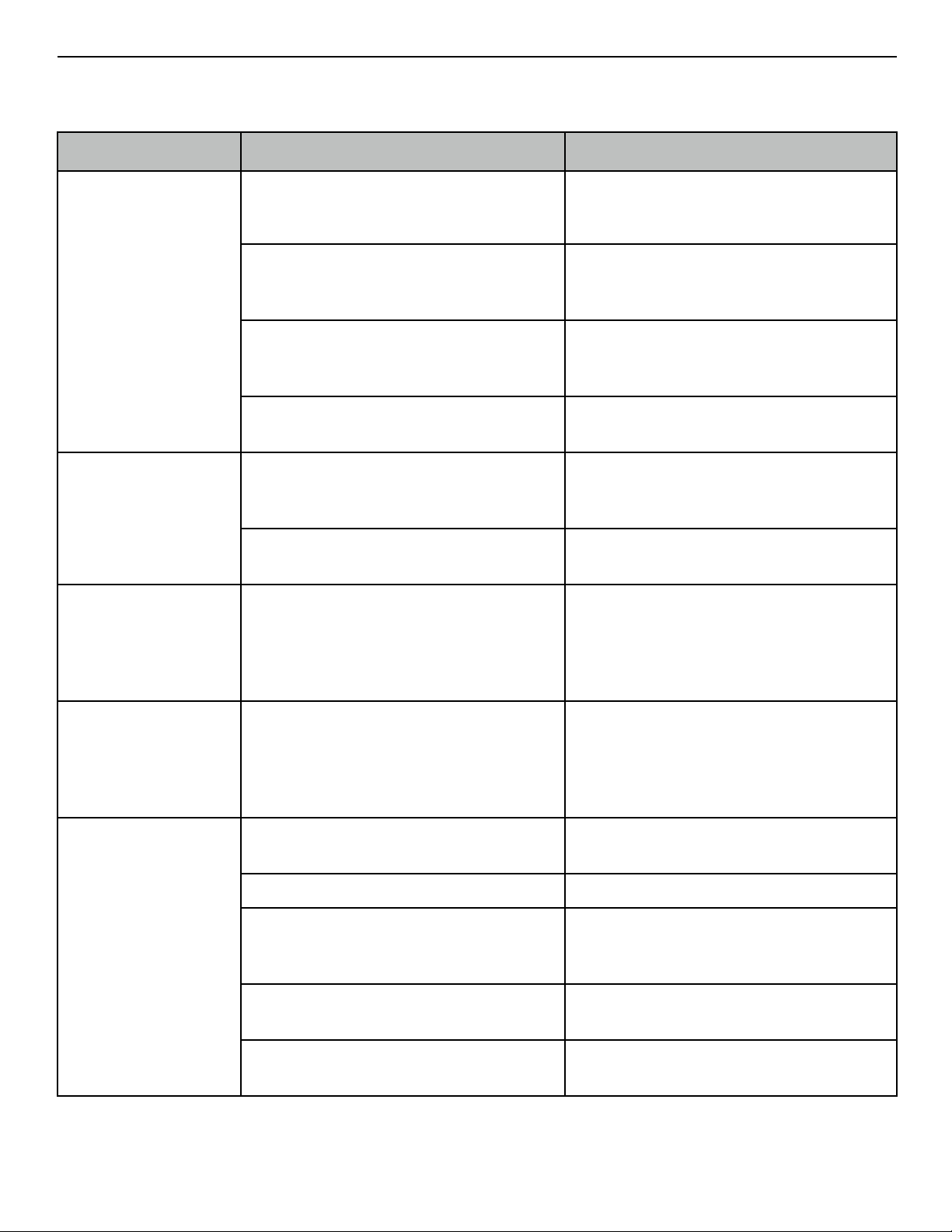
VS0 coin operated models are
outfitted with a stainless steel
coin meter. The coin meter is
divided into an upper section,
which houses the coin acceptor and timer, and a lower
section, that is the money box where coins are collected
once accepted. The coin meter uses a unique BlockLock
locking system that provides maximum security, positive
locking, and ease of use. Because of the high security
provided by the BlockLocks, it is advised that a record of all
key numbers be kept in case of key loss.
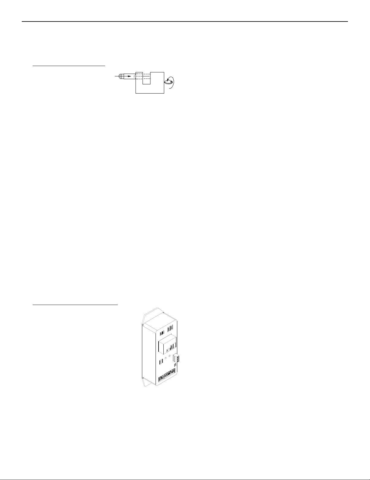
To open the faceplate or money box lock simply insert the
key into the keyhole and turn 1/4 turn clockwise until the
shackle ejects. Do not place your finger against the shackle
when opening as the shackle is spring loaded. If the shackle
does not eject far enough to permit the opening of the
faceplate or money box, simply push the shackle back in
and open the lock again. Note that once the lock is open the
key cannot be removed until the lock is closed again.
To close the faceplate or money box lock, ensure that the
faceplate or money box is fully inserted. Push the shackle in
fully until it clicks into place and the key rotates counter-
clockwise back to its original position. The key can now be
removed from the lock. To ensure positive locking, the key
cannot be removed from the lock until the lock is fully
closed.
2.1.2) Coin Acceptor & Timer Setup
Behind the faceplate of the stainless
steel coin meter is the MTV840 timer
where both coin and time settings are
made. The coin acceptor is mounted to
the inside of the faceplate. Before
opening the faceplate, disconnect
power to the vacuum. Unlock the
faceplate and set the faceplate on the
top of the coin meter. The wire leads
from the coin acceptor on the faceplate
to the timer inside the coin meter are
long enough to allow the faceplate to be set on top of the
coin meter.
For vacuums equipped with iCoin electronic multi-coin
acceptors, refer to the instruction manual supplied for the
coin acceptor to set which coins the coin acceptor will be
enabled to accept. This step must be done first before
making the coin and time settings on the timer. Because
the iCoin acceptor needs to be powered up for setup,
ensure that the faceplate with the coin acceptor is sitting on
2.0 SETUP & OPERATION

3.0 MAINTENANCE
3.1 LOCKS
Because of the high security provided by the locks on your
vacuum (VS0 coin operated models), it is advised that locks
be maintained with a light lubricant (e.g. WD-40) such that
they continue to operate smoothly.
3.2 MOTORS
Periodically inspect the brushes of the motors. Replace
motors or motor brushes when the brushes are less that
3/8” in length.
3.3 FILTER BAGS
Filters bags should be inspected and cleaned frequently. To
protect the vacuum motors, bags should be replaced
immediately if there is an opening in a bag or if there are
signs of wear that could lead to an opening in a bag.
3.4 CLEAN OUT BINS
Disposing of dirt and dust that collects in the clean out bins
on a regular basis will reduce the amount of dirt that the
filter bags are exposed to. The bins are removed through
the clean out door.
coin, set switches 2, 4, 8, and 16 ON. To configure the
vacuum for 40 seconds per coin, set switches 8 and 32 ON.
If all the Seconds Per Pulse switches are off, the vacuum
will be set for 1 second per coin.
The green POWER light on the timer shows that power is
being supplied to the timer. The red LOAD light indicates
that the vacuum is operating. The reset button resets the
timer and cancels any existing time. Use a pen or similar
object to press gently on the recessed reset button.
2.3 VS0 (Toggle Switch Operated Models)
The non coin-operated toggle switch model has a single
toggle switch to start and stop the vacuum. Move the toggle
switch up to the on position to start the vacuum. To stop the
vacuum move the toggle switch to the down off position.
The green POWER light on the timer shows that power is
being supplied to the timer. The red LOAD light indicates
that the vacuum is operating. The reset button resets the
timer and cancels any existing time. Use a pen or similar
object to press gently on the recessed reset button.
2.2 VS0 (Pushbutton Operated Models)
The non coin-operated pushbutton model has 2
pushbuttons, one start and the other stop, mounted on the
front of the control box. Pressing the green start button will
cause the vacuum to operate for a period of time as
determined by the timer located in the the control box.
Pressing the start button while the vacuum is operating will
not add additional time to the current operating period. To
stop the vacuum from operating prior to the end of the time
period, press the red stop button.
The length of time that the vacuum will operate when the
start button is pressed is set on the MTV840 timer. To
access the MTV840 timer, remove the 4 screws holding the
front cover to the box. Before opening the front cover,
disconnect power to the vacuum. The MTV840 timer has
two banks of switches labeled #Pulses to Start and
Seconds Per Pulse. To turn a switch on, depress the top
side of the switch until it clicks positively into the down
position. To turn a switch off, depress the bottom side until it
clicks positively into the down position. Note the ON arrow
points up which is the side of the switch that must be in the
down position for the switch to be ON. Ensure that each
switch is in either the on or off position, and not halfway in
between.
Set the switches labelled #Pulses to Start such that they
are ALL in the OFF position. These switches must be set all
OFF in order for the pushbutton operation to work correctly.
Set the switches labeled Seconds Per Pulse such that they
total the number of seconds that the vacuum is to operate.
For example, to configure the vacuum for 30 seconds per

Symptom
Probable Cause
Corrective Action
Vacuum does not start.
No power to vacuum.
Ensure that 120 or 240 volts is being supplied at
the junction box in the vacuum, depending on the
power requirements of your model.
Fuse or fuses blown.
Check and replace fuses to the vacuum motors.
See Symptom Vacuum motor fuses or fuses blown
for further action.
Switch settings on timer are not set correctly
(VS0 coin-operated or pushbutton operated
models).
See section 2.1 or 2.2 to ensure that the timer is
settings are correct.
Stop button stuck in depressed position
(pushbutton models)
Repair or replace stop button.
Vacuum does not stop.
Switch settings on timer are not set correctly
(VS0 coin-operated or pushbutton operated
models).
See section 2.1 or 2.2 to ensure that the timer is
settings are correct.
Timer or relay may not be working correctly.
Verify operation of timer or relay to ensure that it is
shutting off vacuum motors.
Circuit breaker trips.
Electrical supply, including breaker and wire size,
may not be sufficient to operate the electrical
requirements of the vacuum and any other
devices that may be operating on this same
circuit.
Contact a certified electrician to check and ensure
that breaker and wire size are sufficient for the
vacuum and any other devices operating on the
same circuit.
Vacuum motor fuse or
fuses blown.
Motor brushes may be bad or shorted.
To confirm the problem is with one or more
motors, use a clamp meter to measure the current
draw of the motor(s). If the current draw exceeds
the specifications of the motor(s) then replace the
motor(s) or motor brushes.
No or low suction.
Hose cut or clogged with debris.
Check hose for cuts or debris and repair or
replace as necessary.
Filter bags clogged.
Check filter bags and clean.
One or both of the motors may not be functioning
properly.
Check motor fuses. If fuse is blown see Symptom
Vacuum motor fuses or fuses blown for further
action.
Clean out doors not closed tightly with latch.
Ensure that latch is holding doors closed tightly.
Latch can be adjusted if required.
Clean out door gaskets or motor gaskets worn.
Replace leaking gaskets. Ensure that motors are
held down securely by bracket or springs.
4.0 TROUBLESHOOTING

Model & Description
Voltage
Amperage
Motors
Fuses
VS0
120
17
2
2 of 10A 3AB
VS03
120
25
3
3 of 10A 3AB
VS0H
240
8
2
2 of 8A 3AB
VS03H
240
11
3
3 of 8A 3AB
5.0 SPECIFICATIONS

COIN BOX
(OR CONTROL BOX WITH PUSH BUTTONS)
RESET
LOAD POWER
COIN
ACCEPTOR
COM N.O.
HOT COM
COIN
COUNTER SUPPLY
HOT NEUTRAL
SETTINGS
COINS
TO START SECONDS PER COIN
1234
OPEN OPEN
1234 5 67 8
REMOTE
RESET
16
32
64
128
256
512
4
8
4
8
1
2
000125
YELLOW
BLUE
BLACK
INPUT
GRD
120VAC
COIN COUNTER
10AMP
INLINE FUSES
(120VAC MOTORS)
120V
VAC
MOTOR
GROUND STUD
120VAC 20AMP SUPPLY
BLACK (LINE)
12 GA.
WHITE (NEUTRAL)
12 GA.
GREEN (GROUND)
GREEN
BLACK
WHITE
PUSH BUTTON
STOP/START
MAGIKIST CP900
ELECTRONIC
COIN ACCEPTOR
NC NO COM
MECHANICAL
COIN ACCEPTOR
WITH
MICROSWITCH
OR
OR
(NO)
START
(NO)
STOP
JUNCTION
BOX
MTV840 TIMER
RED
120V
VAC
MOTOR
120 Volt 2 Motor
VS0-CP coin operated model
VS0-CD coin operated model
VS0-PB pushbutton model
V1.1 20140513
ALTERATE WIRING
FACTORY WIRING

ALTERATE WIRING
FACTORY WIRING
COIN BOX
(OR CONTROL BOX WITH PUSH BUTTONS)
RESET
LOAD POWER
COIN
ACCEPTOR
COM N.O.
HOT COM
COIN
COUNTER SUPPLY
HOT NEUTRAL
SETTINGS
COINS
TO START SECONDS PER COIN
1 2 3 4
OPEN OPEN
1 2 3 4 5 6 7 8
REMOTE
RESET
16
32
64
128
256
512
4
8
4
8
1
2
000125
YELLOW
BLUE
BLACK
INPUT
GRD
120VAC
COIN COUNTER
10AMP
INLINE FUSES
(120VAC MOTORS)
120VAC 30AMP SUPPLY
BLACK (LINE)
10 GA.
WHITE (NEUTRAL)
10 GA.
GREEN (GROUND)
GREEN
BLACK
WHITE
PUSH BUTTON
STOP/START
MAGIKIST CP900
ELECTRONIC
COIN ACCEPTOR
NC NO COM
MECHANICAL
COIN ACCEPTOR
WITH
MICROSWITCH
OR
OR
(NO)
START
(NO)
STOP
JUNCTION
BOX
MTV840 TIMER
GROUND STUD
120V
VAC
MOTOR
RED
BLUE
120V
VAC
MOTOR
120V
VAC
MOTOR
120 Volt 3 Motor
VS03-CP coin operated model
VS03-CD coin operated model
VS03-PB pushbutton model
V1.1 20140513

ALTERATE WIRING
FACTORY WIRING
COIN BOX
(OR CONTROL BOX WITH PUSH BUTTONS)
RESET
LOAD POWER
COIN
ACCEPTOR
COM N.O.
HOT COM
COIN
COUNTER SUPPLY
L1 L2
SETTINGS
COINS
TO START SECONDS PER COIN
1234
OPEN OPEN
1234 5 67 8
REMOTE
RESET
16
32
64
128
256
512
4
8
4
8
1
2
000125
YELLOW
BLUE
BLACK
INPUT
GRD
240VAC
COIN COUNTER
8AMP
INLINE FUSES
(240VAC MOTORS)
240V
VAC
MOTOR
GROUND STUD
240VAC 15AMP SUPPLY
BLACK (L1)
14 GA.
RED (L2)
14 GA.
GREEN (GROUND)
GREEN
BLACK
Red
PUSH BUTTON
STOP/START
MAGIKIST CP900
ELECTRONIC
COIN ACCEPTOR
NC NO COM
MECHANICAL
COIN ACCEPTOR
WITH
MICROSWITCH
OR
OR
(NO)
START
(NO)
STOP
JUNCTION
BOX
MTV841 TIMER
BLUE
240V
VAC
MOTOR
240 Volt 2 Motor
VS0H-CP coin operated model
VS0H-CD coin operated model
VS0H-PB pushbutton model
V1.1 20140513

ALTERATE WIRING
FACTORY WIRING
COIN BOX
(OR CONTROL BOX WITH PUSH BUTTONS)
RESET
LOAD POWER
COIN
ACCEPTOR
COM N.O.
HOT COM
COIN
COUNTER SUPPLY
L1 L2
SETTINGS
COINS
TO START SECONDS PER COIN
1 2 3 4
OPEN OPEN
1 2 3 4 5 6 7 8
REMOTE
RESET
16
32
64
128
256
512
4
8
4
8
1
2
000125
YELLOW
BLUE
BLACK
INPUT
GRD
240VAC
COIN COUNTER
8AMP
INLINE FUSES
(240VAC MOTORS)
240VAC 20AMP SUPPLY
BLACK (L1)
12 GA.
RED (L2)
12 GA.
GREEN (GROUND)
GREEN
BLACK
RED
PUSH BUTTON
STOP/START
MAGIKIST CP900
ELECTRONIC
COIN ACCEPTOR
NC NO COM
MECHANICAL
COIN ACCEPTOR
WITH
MICROSWITCH
OR
OR
(NO)
START
(NO)
STOP
JUNCTION
BOX
MTV841 TIMER
GROUND STUD
240V
VAC
MOTOR
BLUE
WHITE
240V
VAC
MOTOR
240V
VAC
MOTOR
240 Volt 3 Motor
VS03H-CP coin operated model
VS03H-CD coin operated model
VS03H-PB pushbutton model
V1.1 20140513

CONTROL BOX
10AMP
INLINE FUSES
(120VAC MOTORS)
120V
VAC
MOTOR
GROUND STUD
120VAC 20AMP SUPPLY
BLACK (LINE)
12 GA.
WHITE (NEUTRAL)
12 GA.
GREEN (GROUND)
GREEN
BLACK
WHITE
JUNCTION
BOX
RED
120V
VAC
MOTOR
120 Volt 2 Motor
VS0-T toggle switch model
2 POLE TOGGLE SWITCH
20A 125VAC
CONTROL BOX
8 AMP
INLINE FUSES
(240VAC MOTORS)
240V
VAC
MOTOR
GROUND STUD
240VAC 15AMP SUPPLY
BLACK (L1)
14 GA.
RED (L2)
14 GA.
GREEN (GROUND)
GREEN
BLACK
RED
JUNCTION
BOX
BLUE
240V
VAC
MOTOR
240 Volt 2 Motor
VS0H-T toggle switch model
2 POLE TOGGLE SWITCH
10A 250AC
V1.1 20140513
V1.1 20140513

120V
VAC
MOTOR
GROUND STUD
120VAC 20AMP SUPPLY
BLACK (LINE)
10 GA.
WHITE (NEUTRAL)
10 GA.
GREEN (GROUND)
GREEN
BLACK
WHITE
JUNCTION
BOX
RED
120V
VAC
MOTOR
120 Volt 3 Motor
VS03-T toggle switch model
240V
VAC
MOTOR
GROUND STUD
240VAC 15AMP SUPPLY
BLACK (L1)
12 GA.
RED (L2)
12 GA.
GREEN (GROUND)
GREEN
BLACK
RED
JUNCTION
BOX
BLUE
240V
VAC
MOTOR
240 Volt 3 Motor
VS03H-T toggle switch model
V1.2 20201002
V1.2 20201002
120V
VAC
MOTOR
BLUE
240V
VAC
MOTOR
WHITE
CONTROL BOX
10AMP
INLINE FUSES
(120VAC MOTORS)
TOGGLE SWITCH
30A 125VAC
CONTROL BOX
8 AMP
INLINE FUSES
(120VAC MOTORS)
TOGGLE SWITCH
15A 250VAC

VS0 & VS0H
26
26A
13R
13L
2
3
6A
9
29
31
32
14A
26
26A
8
32
6
19
30
14
22
36
25
24
23
36
25
24
23
1
11
12
17
20
17
20
21
4
5
5A
28
7
15 16
7
15A
V1.1 20140513

Item
Part Number
Description
Qty
1
CBL1V-A0NA
Coin Meter Assembly (includes CBL102, CBL103, & CBL106)
1
2
VACWWGB16
Vacuum hose, 1.5”, 16ft
1
3
VACTAS
Aluminum vac nozzle w/cuff
1
4
MTV840
Electronic timer (120 volt vacuums)
1
MTV840-240
Electronic timer (240 volt vacuums)
1
5
ELCFUSE-3AB10
fuse, 10A. 3AB (120 volt vacuums)
2
ELCFUSE-3AB8
fuse, 8A. 3AB (240 volt vacuums)
2
5A
ELCFUSE-ILG1
inline fuse holder
2
6
VS6
motor retainer bracket
1
6A
VB6A
lock nut
1
7
ELCBOX-JB884
Control box for pushbuttons
1
8
VS8
vacuum body
1
9
VS9
filter bag
4
11
CBLV102
faceplate
1
12
CBL103
money drawer
1
13L
VB13L
dust container
1
13R
VB13R
dust container
1
14
VB14
vac motor (120 volt vacuums)
2
VB14-240
vac motor (240 volt vacuums)
2
14A
VB14A
vac motor brush (120 volt vacuums)
4
VB14A-240
vac motor brush (240 volt vacuums)
4
15
ELCSW-220A-SGL0
start push button
1
15A
ELCSW15DS
toggle switch
1
16
ELCSW-220A-SRL0
stop push button
1
17
CBL106
block lock with 2 keys
2
19
VB19
stainless steel dome
1
20
CBL107
key for block lock
2
21
VB17
nut 1/2” with lockwasher
4
22
VB7A
gasket, motor to motor mount
2
23
VS25-R
rivet
8
24
VB25G
door gasket
2
25
VB25
door
2
26
VB26
door clasp
2
26A
VB26-R
rivet
8
28
CP900, CMX21
electronic coin acceptor, mechanical coin acceptor
1
29
VB29,VB29F,VB29B
vacuum label: english, french, bilingual
2
30
LBL9002
dome label
1
31
ELCDP08
plug 1/2”
1
32
VSB19S
ss screw
6
36
VB36
bottom access cover plate
1
VS0 & VS0H Parts List

VS03 &VS03H
26
26A
13R
13L
2
3
6A
8
9
29
36
19
31
32
32
14
14A 22
6
26
26A
30
1
11
12
17
20
17
20
21
28
4
55A
7
15 16
25
24
23
25
24
23
7
15A
V1.1 20140513

Item
Part Number
Description
Qty
1
CBL1V-A0NA
Coin Meter Assembly (includes CBL102, CBL103, & CBL106)
1
2
VACWWGB16
Vacuum hose, 1.5”, 16ft
1
3
VACTAS
Aluminum vac nozzle w/cuff
1
4
MTV840
Electronic timer (120 volt vacuums)
1
MTV840-240
Electronic timer (240 volt vacuums)
1
5
ELCFUSE-3AB10
fuse, 10A. 3AB (120 volt vacuums)
2
ELCFUSE-3AB8
fuse, 8A. 3AB (240 volt vacuums)
2
5A
ELCFUSE-ILG1
inline fuse holder
2
6
VS6-3
motor retainer bracket
1
6A
VB6A
lock nut
1
7
ELCBOX-JB884
Control box for pushbuttons
1
8
VS8-3
vacuum body
1
9
VS9
filter bag
4
11
CBLV102
faceplate
1
12
CBL103
money drawer
1
13L
VB13L
dust container
1
13R
VB13R
dust container
1
14
VB14
vac motor (120 volt vacuums)
3
VB14-240
vac motor (240 volt vacuums)
3
14A
VB14A
vac motor brush (120 volt vacuums)
6
VB14A-240
vac motor brush (240 volt vacuums)
6
15
ELCSW-220A-SGL0
start push button
1
15A
ELCSW15DS
toggle switch
1
16
ELCSW-220A-SRL0
stop push button
1
17
CBL106
block lock with 2 keys
2
19
VB19
stainless steel dome
1
20
CBL107
key for block lock
2
21
VB17
nut 1/2” with lockwasher
4
22
VB7A
gasket, motor to motor mount
2
23
VS25-R
rivet
8
24
VB25G
door gasket
2
25
VB25
door
2
26
VB26
door clasp
2
26A
VB26-R
rivet
8
28
CP900, CMX21
electronic coin acceptor, mechanical coin acceptor
1
29
VB29,VB29F,VB29B
vacuum label: english, french, bilingual
2
30
LBL9002
dome label
1
31
ELCDP08
plug 1/2”
1
32
VSB19S
ss screw
6
36
VB36
bottom access cover plate
1
VS03 & VS03H Parts List

ELECTRICAL SUPPLY
JUNCTION BOX
120° TYP.
7
2
1.5
.75
.75
D 0.50
A
4.5
CHANNEL WIRE ENTRANCE HOLE
1.00"DIA EDGED WITH SERRATED
GROMMETTING
DETAIL A
MOUNTING TAB
DETAIL BOTTOM VIEW
22"
58"
9.5"
1.25
30
19"
18
20.5
V1.1 20140513
VS0
•Dimensions
•Mounting Pattern
•Junction Box Location

WARRANTY
Magikist vacuums are warranted by the manufacturer to be free from defects in material and workmanship for one year from date
of manufacturer's shipment, provided the equipment is installed and operated in accordance with factory recommendations and
instructions. This warranty is limited to repairing or replacing products which manufacturer's investigation shows were defective at
the time of shipment by the manufacturer. This warranty does not cover normal wear, nor does it cover damage caused by neglect,
misuse, accident, faulty installation or tampering in a manner to impair its normal operation. All products subject to this warranty
shall be returned freight prepaid to Magikist Ltd., Winnipeg, Canada for examination, repair, or replacement.
The express warranty set forth herein is in lieu of all other warranties, express or implied, including without limitation any
warranties or merchantability or fitness for a particular purpose and all such warranties are hereby disclaimed and excluded by the
manufacturer. Repair or replacement of defective products as provided is the sole and exclusive remedy provided hereunder and
the manufacturer shall not be liable for any further loss, damages or expenses, including incidental and consequential damages,
directly or indirectly arising from the sale or use of this product.
This warranty is subject to the installation and operating conditions as described in this manual. This warranty does not apply to
optional equipment which may have been supplied with your vacuum. Refer to the warranty supplied with the optional equipment
for information on that equipment's warranty.
Parts originally manufactured by Magikist Ltd. must be used or this limited warranty will be voided. Magikist Ltd. will be absolved of
any liability if parts other than Magikist Ltd. manufactured parts are used.
There are no warranties which extend beyond the description of the face thereof.
This manual suits for next models
4
Table of contents
Popular Vacuum Cleaner manuals by other brands

Miele
Miele S 7000 series operating instructions

Milwaukee
Milwaukee HEAVY DUTY M18 F2VC23L Original instructions

Bissell
Bissell Powerlifter 2259 Series user guide

Panasonic
Panasonic MCV5203 - COMMERCIAL VACUUM Service manual

Vax
Vax Mach 2 SERIES instruction manual

Tornado
Tornado CK-14/1 PRO Operation & maintenance manual