CONE BOARD
WIRE COLOR CHART
ARED YELLOW YELLOW
BWHITE RED RED
CWHITE YELLOW
DBLACK
EWHITE ORANGE
FWHITE GREEN
GWHITE GREY
HWHITE VIOLET
IWHITE BLUE
JWHITE BROWN
1 5 9
2 6 10
3 7 11
4 8 12
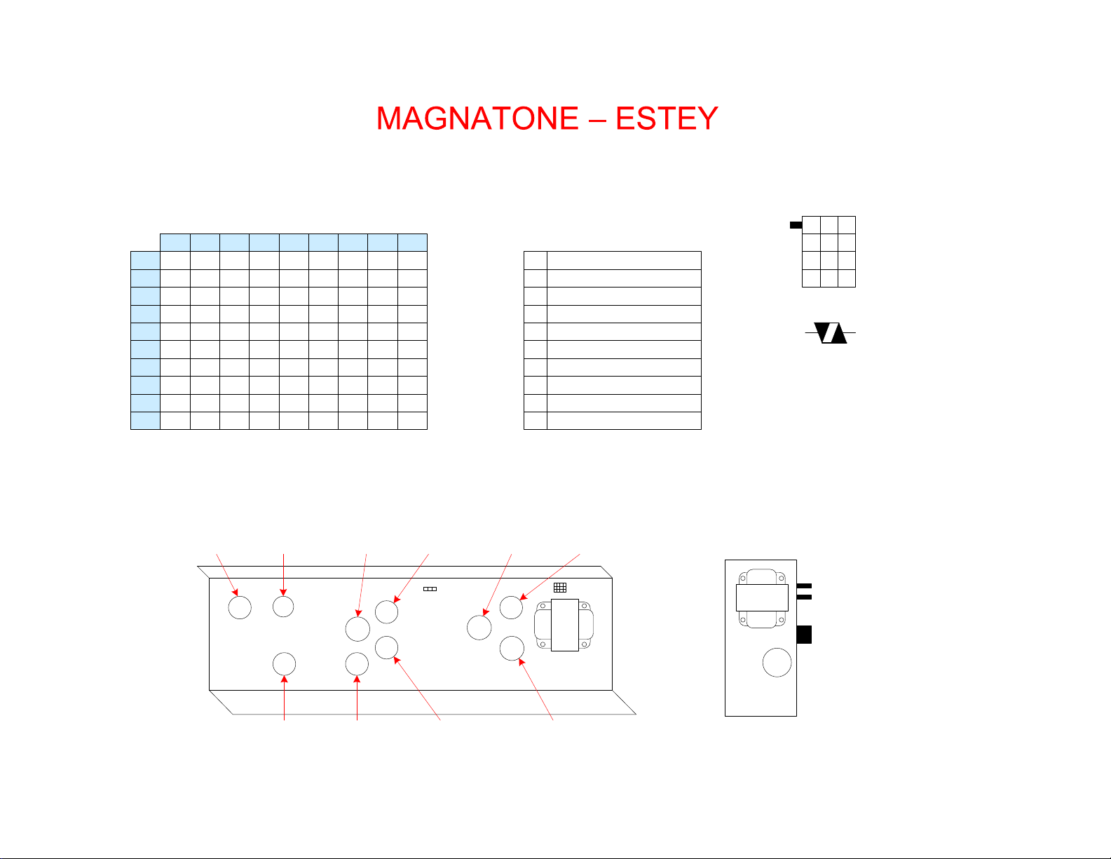
P1-S1 KEY
VARISTOR
MODEL M-10A
NOTES AND EXTRAS
Pot codes: 304-6532
Mfg is Stackpole
Date is 32th week of 1965
AC POWER
FUSE
T1
LYTIC
PS CHASSIS
TUBE VOLTAGE CHART
123456789
V1
V2
V3
V4
V5
V6
V7
V8
V9
121 0 2 HTR HTR 72 00.9 HTR
65 00.8 HTR HTR 84 -1.0 0HTR
75 01.2 HTR HTR 75 01.6 HTR
256 56 90 HTR HTR 104 -0.5 0HTR
273 75 86 HTR HTR 266 70 95 HTR
226 06.2 HTR HTR 226 06.2 HTR
122 01.1 HTR HTR 211 0 2 HTR
241 49 82 HTR HTR 85 0 4 HTR
-15.3 -15.3 3.3 HTR HTR 405 404 X405
V10 -15.3 -15.3 3.3 HTR HTR 405 404 X405
Voltages measured with Fluke 87 DMM referenced to chassis. All controls set to max
CCW. V4 phase shift oscillator was disabled by shorting out the 820K resistor.
V4 V5
V1 V2
V6
V3
V7
V8
V9
V10
S2 SPEAKER
S1 POWER
T2
V10 – 7189A
Power Output
V9 – 7189A
Power Output
V8 – 12AU7
Phase Inverter
V2 – 12AX7
Ch 2 1st Preamp
TUBE LOCATOR
V3 – 12AX7
Ch 1 & 2 2nd Preamp
V1 – 12AX7
Ch 1 1st Preamp
V7 – 12AX7
Reverb Recovery
V6 – 12AU7
Reverb Driver
V4 – 12DW7
Vibrato Oscillator
V5 – 12AU7
Vibrato Modulator