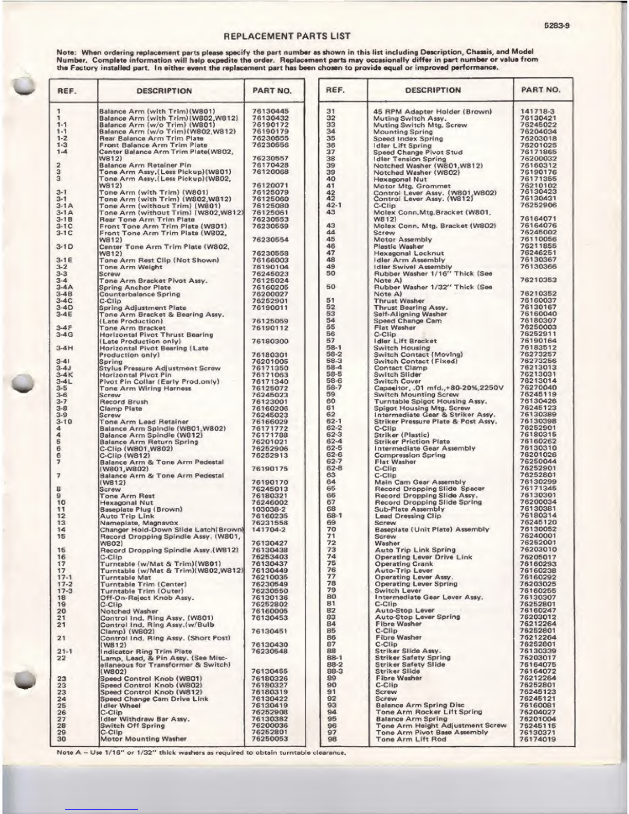
REPLACEMENT PARTS LIST
No,*: Wrm- L>rdur ng rup la Hm^ni ports pluostf specify lha part numb**- #4 tfiown in <hii Hit including Owci-iptio.n, Chnaai*. And Mod*
I
Number. Complvt* information vrlll halp *xpodi£* th* ord«r. Rio^tmtfii pmrn may Mcwienilly drf*** in part numb*r or valu* from
1htr Fntlory installed part In tiichnr Rvnj^» th* rn-plncnrniir.C pnrl hns bwjn chown 1u prcmde uqunl ur irr-prerrrHj p*tfo -Hi-Fincf-.
RFF DESCRIPTION PAHT no. FIEF, DESCRIPTION PART NO.
Balance Arm [with TrimHWSOIJ 7B 130445 31 45 RP MA^4ptDT \~tO Iriilr" 1HrOr/vn \141 718-3
1n,i ....... Arm liJL-i rh Tri rtiTi 1VVRO? WR 13l jn.l^.'r. i/:52 tijH 11!nnQuvi+^In iTj m*WI4H<fl F
l-
1
Gn|r,r*i irm Tr iml iWAnil 7&1<5CH 72
rU1P/i33 nlUrilllnJ .^YH 1LL 11IVI Lu -JLI Qlr¥ HViVV mm. £
1-1 7-G 1^fll 74 ryiOUni in jnjprin-j rft* Ll*^LJJI'
1-2 Davf Oil nnri Arm Trim PlAM 7iH -: P. cq
q
rl-1!t-1'-Tu1_' "J 35 [-ipcflri ln>r9pK Spring 7r. -?fil fl 1K
UjC 'J J L11_
1.3 Pmnp R^l^nr i> A. r^n Tri mt?l n+a
rrrpni r-irti^i ii_ir J-^a rn isi mri ina if? 1rJEDT LITT bpr 111 ]f
fLArrtMr Rnlnnrfi Arm Tri mPhAT1"I'dfl fi 5" 3-7 Sp&OiJ th-*nij4T r*!yL>Ti Stud U1J1_1J^
WR 17^ 7C2 2Q5E7 38 1d'n-rTension Spj'infj "fjiinfim
Ffl#tfl\PUJ sS
2nulanr-fi Arm ft FAift i"i i" Pir*i
L> Q'ul 1Uf] w\Wl 11FTWSWI Hg* rIFF 39 fJjt, T.-. h,1 -n LF. 1r. jp.j.r .! Ij'lI F-l F~l 1J-U; 1"> hjr r__i |hjHj 1^
aTdrlt Arm Axxy.l L-tjxx Plcku plCWflOl J761200SB 3£ 1H tL1TJC cl UtP I 1 MtIVI hFT Uj. 17G1-'3Ii176
Tona A'rti A*v\»\ iL*'"« Pic-ku p1(WB02.. 40 1—lifl "iH i~i iH Ti 31 i r761 713B5
76120071 41 \-loi or Brl ^5 r^i iii iiHt 7B310102
3-1 Ton uArm (with Tr iml [W801 r76125079 42 COAlrn-l L*v*r A«y, (WBOVW0O2] 7G 130423
3-1 Tana- Arm fwlih Trlml IWHl>7 WSl3l 7612'5CiEir>42 Conlrnl i-mvmr Avsf. (W81 21 713 1:3L>431
3-1
A
Tnnrj- Arm (with nut Trirfi? rj |pVr3-0,1i} 761250B0 42-1 76252906
:m aTn •• ii ArrTi liwi EhDUl Tri ml Vifl 175 7&l2-GOFil 43 MoIn- it Cn rin.Mtp. 9racfc; rj-t (W801 r
3-1
E
IR ujr T"Tjrni Arm Tfi rr1ntu 76230553- WE 12) 76164071
3-iC Front T&fta Arm Trim PJae* tWHdl) 7<??3Pli!iR 43 [JdId-x torn. Mtg. Bracket iWS02I 7616^076
3-1C Front Toni Arm THm Flrrhi (Wi202r44 St rfrw 7624E002
WB 12] 7S23C454 45 "k1 DtG rAiwn"ib!v 761 10056
ji |UL_- 1111 l^ll IUEI IT • i 1 m1r11 1 1 r1ll irVa UJ |46 pi mmtlr- L'<nrhl.r
r1D3 Liu TI ami 1L17621 18SS
WB 12) 7fi7Jin ciFiR 47 76240251
^=Ton* A»m Rri^i Clip (NDt $ltpwnf rt> 1tHJUUJ 48 1dlflr jAthi iA"S5u mPi y761 3D367
3- Z" T~ nn n- irm'Aim inHh7*L Iqni nj 49 1rSh'ir luiiiuAl ArHLfl-ftsh "\V
puIHF iJrrlVVP tPm rW^HI" BrF
^
ftubh-flr iVaxhc-r 1/1 G" Thick rS-crQ
761303E6
50
3-4 1lUff J*-h rrr1O
T
kr-.v LntQ^ ."-S 53 v
-
7fi13^Q5d fsu tL" Ap 7621 02S2
S^riftQj Anchor Pi-tinrj tci cj-inj-ic
'f> CrU-L 50 LLJ IJE^Ir iSal IUI 1J-Zi -iZ I11IL ¥. 1i->L^D
3-46 Cnun'tirrbDlQinc'D -Soring 7ft^fWlfj?7 NChlfj Ap 7621 0252
t+l—C-C'l prtT-+ Jj; yij 151 iii iLi j.l wninor 7rs 1KCWj-T7
apr ing AQ;U 5tmoni t*i did 7A1 OrfVIl 1
ral aU'J iTEr1'*- inruxi DHr
i
aa uAny, 7C 1201 Ei 7
'fl 1..-Li Itp-X
To*** Afm 6'f>cK*T Sr BQ'D'ing Af^y. r±3
f1n+nC1r.-1 i-l .— +ir-i r-i 1
1LDtD KrQUC11n17ft1 ItfUl-Q 54 ~i E:11k:1. 1nn riLjru hi in76130307
Ton* Aftlt BflKh^ii TRI no 117
/o- 1y«y 1ii Bnm. wnvri up 7«7
3-4G r3-r .—.r-. +-1 1D!nn+ Thmr+ Qnarin n
r%G :ZOnlj 1rrlVDI 1nU5TEa-^rflriiip 56 C-CI'P- 7625291
1
tL-BI4 FrtHjij ttNsn only] tfS.1 nrinnn s? liHlrfir 1Iff ftrnr-Liit
uiui i—iix dro1.f.iji. 7*7 1t>n iR4
3-4N Mn rizontnl Pivot Brf-nrinrf 4LaU SQrl Swlr^h HOytlRig i1? 1-—-lJ J1aC
F?n-:!ui -iQ "fifi 1v>-j j jiVitc n>_i ni-H ct 1 PinQvn
g
'fl* JJ* 3J
3-4' :: r--
1
;
Tft irirtcr
'Pi U1UU3 58-3 rr .1.
;
T,i. kHnntn^T J^iviirtt
Z1 1 T| >. ll L,e>nTJlCT 13-lKUtlir rU1!.' jl tJLl
3-4JJ^tv Sli*^ Kriri'iu rC' Ad| uirmcrfeT &crrrw i": 1"r 1""afi nSfi-4 762 t201
3
J*—1*IS rlO^iZOn tftfl PIvO F. Pin Jrj 1f1UwJ 58-S JnlILn JII LI W1
3-4 LO.1 1.-J-. +AEn f*" 1Isr Hrfj krfc uDrjxrl r-i r-. 1 "l
raWT rln LiQHaT !,b jr! VrrQ'D.aRl 7R1 71 "lift
/DIM J*4-U SE- G76213014
a. i
.
TO**rf flttaui WiriftQ Hrjr~nrt|.f JP1/ t 58-7 f'.ru.. l+nr rnl mfrl fftn_7f1nA P'JnOU r1?* WW akf
Tj: Scraw "3 JSC: jfifl r. 59 Oili_ nihi ci^ntinLj ^trun 76245 119
rUal^+Lr 113
2- 7Rr»oa-rfJ Qr|jifh 1"S^orii
JpI4>#Vvl 60 Turntni-ilfi ^rbiorVC UclilAljfUI AiUV
1UT 1 1 LU4-11d-J3 Lr 1kj JLPIWIIII| nH|fi
-u:
J-O >- l__ni.._
LiPD-mp r'are /PI OUfUu 61 Sp^AOl Hcjy-finfl Mrfli S?-rBr'rW 7p^2J.R 121
r—1al +s-11!i_J*
MP Scrirfiry 7fi"S jail's 62 1ntn-rmMrlJnEn L~! rt-Ar ft fli1A-UIV
111Lul Fr1vU^a1VUaTflr -UJ -_P Hfc ^ii^n |J| p1'A UH KFI
3-i0 T.".n_i jY p>-1,-, ,JRai iinAP
1OTV M.I LU'JO r*tPlJjinWF jrj iOkTU^Tt 62-1 5r.ri k&r PrL^xxjj rc* Pi Dtrj* &Pdx^ Assy. 7613D3 99
4fiulnrifi Arm finindln fwarfll MSr>7k
IKrLrl J^l III A|J 11 I^LII U^ffraU 1j1¥QLTj. r76 171 772 ^2 2C-CI Ip 762529 01
4y|j i7iv62^3 I->irikcr ijPlBEtlcj 76 13031
5
5P9I nn^m Arn\ +1irn ^rnr inra
Oul Ul IPLQ J^l III niTLUI 11uJJIIII|^ 7C2 D105 t
HU1UiE 162-4 ^l/ikfi^ Prif Ei fifl PlRTr? 7616Q2 62
s1" fiJrt. JlAjDJ-i 1Li/3 ni">
b
ft- J?L "Ju1ntBr rruirl i-^tA Citrjiw AtiAmhl>J
|1.n,iaiO -l i
s_i ni—i 1|_p ino- .£ rG2-G 4-1 ri drfc-. ri. p-fl «.1iTi Pi ^orlrba 76201026
7n'1*Cj jX fnrt Pu Tin Pi n- Afin PnrldivKjil 62'? Fl-ot VVaihar 76*£0CH*
'1A.1 Ul |""l 1LNj-fl; rT.-Tp L7fi iami 7*> 62-B C-CI In 76252901
7[il rj Arm ^Tant Arm Podcxtjl 03 C^CIIp 762B2&&1
1Wfl-121 76140170 64 Mii iih Cirn iTIr.iiir Af^ambly 761 302 99-
HSiV.v 7G24S012! 6S FturcaTdi Droppli*B Slidy Sp-fril-tjr 7G171IM5.
gTDnu Arm y51. 761 8032
1
6B RKorrJ D'Topplnaj 3-1 Ida- Axxy. 76130301
1D Hmks'l'jfjn ml rfut 7G24Fi002- 57 FtiKordi Dropping SlirJu Sp'i"^
1iQaSU pi BtD; Plu U*! Br Ov* "^J 1CI3CI3B-2 SB 5ub-Pi4hf> APHrnbly 76130381
12- Aifii^o Trip ^rlnlc ruii,j L^r u_ v_r BB-1 Lbb^J [^rcx5iin nCip76180^14
13 NBmcpliBlfl, MFJQn-3VOK 7623 1553 &Sr 7624E1 20
14 C~*l*i jii"ioi>r h-En If1Down 'il 1flsi Lnrt ch(6ro hj nrJ 141 !?"£>4-2 i70 HiMiplaio (unit P" l-o in 1AxV?mb'y 76130O57;
IS ri LP_ LJ 1LJ U1U|JLF llr/U ofJFI lull mijf ,1TTUL11.71 76240001
7fi 1"jCjI ".' .'
j. ? i.ai..— r,- 72 7635?O01
rLrfr^r^fl r^i r^ri i^liu iiiu ^|-ii Iiu in p^i*y -
'
745 130d3A 73 Anhh Trln 1ink SCnrEnfl
muuj iri|j
—
fc im-J K~ pi iih 7620301
1GG-Cllp 7f;n c. Tjl ,-\ -> 74 nn*rnlirtfi 1rluAr Vl i'cuA bErik
wi^nranny livpi uirvv Linn 7riJfjRfl1 7
iQCUDU
1
r
•TP
1fi 1 1 1 i E.TN.I tr j-.-H. r-i -inr -n inrn," ikd-r.-'j i'"jfi 1-JlfWLq 7
JU1_t'JM-l3 75 €jo.DTiiE In Crn nk.
17 Tiirnt»hln Jkii'Fi^hP hi Tr irn 1-' LA'H fl"' '.Vfl 1?' 7fi 1^CkidCl
i" t11i?H#*F"lTf 76 i"i VK"0 Irip Ltvfr rrJ >i iJ- u
1TU1 Ti jjlpaUAhiit
IUrriLi; jjQirf 'fl-< WHW T7 ^l^pDTEkE in^ L-EyvF_if j^s-xy. rcp ilhj^^jC
17-2 iurnEAnirS lrim kLionic* j78 r"i rVji rap inn 1a-i ap^nrlnn 'Ot L'iJ LFJ
i^-j .._.tli .>JV 7$ Cuj111— H1HLTMr
IrVI LL 11LUtVI 1'.1 L1Ju'
19 r"-. -U ,,"S _tj ruwt lV rn -.U Arn.-
LJTI jH^nLrlErj|rnCI NnCD M'I V.fv 11M1F 1Jo 00 1r~i Tii rfr'i rHTA Tn njhr 1J"l '_' n.rj2j uur xrj jyjy ^
np-1 &1 C-Clip 7G-2 53B.A-I
JLJ ^U^nQnbir11
k_l r-i. h-I-. -:-| Ulirh.Lr
11arc nca v/as-~cr/O 1OLHJU5 S2 Autn-StPp Lfjv«&f 76100247
r'nArHAl 1r"i -JrjjpLA ^j. /jii rYF-'ll? r^n 1rfl IiJU4JJ 83 A.ULLJ—^tO"D Liwr S-nrinP 7G202015
21 r"" .-u +r.—.1|nH Qlnn A-mmt ii'mi/R ii111
'_i 1jn lr
C
11ino. ning i' y. s
v
1li- ui34 Fltir* WatllV 7621226d
7A1 'trU.K 1
..- 1..'114 J1fjB- C-CH p76552901
2
1
r"" j-. 1-1 +rj-i 1Inrl rQIriA A^Lbu fChilf! P1 P
1
B6 Fihwn WaihQ? 76212263
"'. VR ! I 76130420 a? C-ClSp 76453641
21-1 inrl 1.- nthr rQirtrJI TflrfVl PljhTA S3 1Str ikflr £1 ido Aiiy. 76 t30339
22 1nmn 1ji *r-l K- Pirn Amr I^An Mltr- 08-1 5x' iSc-Rr" Siifiqtv Kpr in 3
•llr)n*Qut ior Trjintforma-r 0* ^wicchl sa-2 |ijtrlkiHr Sv<«ty Slid* 7G1E407E
!WH-D2
1
761 53 tc icri mi
^61 6-^0 ?
23 Sprtd COrttroI K^i3b <WSD1
1
76190326 S9 Fibre Wniheir 7P3212264
23 SpcmdControl Knab^WftOftt 761S0327 90 C-Clip 76252801
23 5e*tdi Con-tfol Krtob <WB12h 761 303 19 iHl 5cnflw JG24B123
24 KpirRCI i\ h.mqn c: nni Drlva Link 76130422 92 70246121
2& ldl*r Wh**l 76130419 93 eilfK* Arm Spring Disc
2a C-CNp 762 52903 94 Tfirtfl ArTn RtKhar L11Spwine 7S204027
27 IdlV Wilhd**w B«r A«V- 7fl" 13035-2 SB 5JSlB-rwi Arm Spring 76201004
2S SwiCch Ofl Eprinn 76200036 ^6 rDnu Arm Ho-lghT AdPu-iTrri4ni Str*W 7G2461 16
26 702 52801 37 Ton# Arm Pivot &p» AisofiTibEy 76130371
3D WOTOr rrlOU PTlnn HrYaihtf 7fl-25O0» 93 Tan* Arm Lift Rod 7G1 74019
Vi, I... AUM 1710"" of 1/32" (tlFCftL irrMh«TE nrfrqulr*d rn CbtflEn +uroi-*bl* clnr