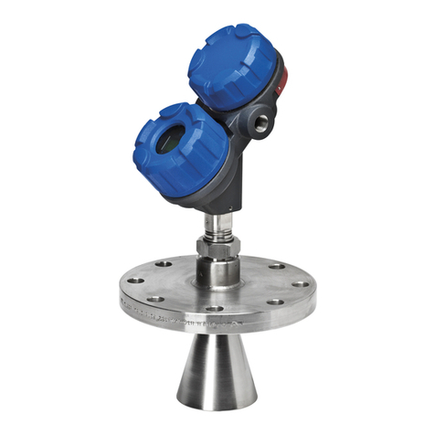
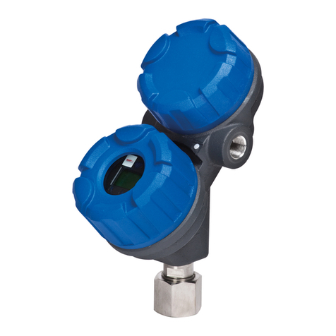
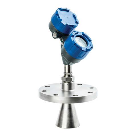
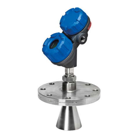
Magnetrol Pulsar R86 User manual

2014/68/EU
High Performance 26 GHz
Pu se Burst Radar
Leve Transmitter
Installation and Operating
Manual for Pulsar®Model R86
with HART®output
Software Version 1.x

BE 58-603 Pulsar® Model R86 Radar Transmitter
Read this Manual Before Installing
This manual provides information on the Pulsar®Model
R86 Radar transmitter. It is important that all instru -
tions are read arefully and followed in sequen e. The
QuickStart Insta ation instru tions are a brief guide to the
sequen e of steps for experien ed te hni ians to follow
when installing the equipment. Detailed instru tions are
in luded in the Comp ete Insta ation se tion of this manual.
Conventions Used in this Manual
Certain onventions are used in this manual to onvey
spe ifi types of information. General te hni al material,
support data, and safety information are presented in nar-
rative form. The following styles are used for notes, au-
tions, and warnings.
NOTES
Notes ontain information that augments or larifies
an operating step. Notes do not normally ontain
a tions. They follow the pro edural steps to whi h
they refer.
Cautions
Cautions alert the te hni ian to spe ial onditions that
ould injure personnel, damage equipment, or redu e
a omponent’s me hani al integrity. Cautions are also
used to alert the te hni ian to unsafe pra ti es or the
need for spe ial prote tive equipment or spe ifi mate-
rials. In this manual, a aution box indi ates a poten-
tially hazardous situation whi h, if not avoided, may
result in minor or moderate injury.
WARNINGS
Warnings identify potentially dangerous situations or
serious hazards. In this manual, a warning indi ates an
imminently hazardous situation whi h, if not avoided,
ould result in serious injury or death.
Safety Messages
The PULSAR Model R86 system is designed for use in
Category II, Pollution Degree 3 installations. Follow all
standard industry pro edures for servi ing ele tri al and
omputer equipment when working with or around high
voltage. Always shut off the power supply before tou hing
any omponents. Although high voltage is not present in
this system, it may be present in other systems.
Ele tri al omponents are sensitive to ele trostati dis-
harge. To prevent equipment damage, observe safety
pro edures when working with ele trostati sensitive
omponents.
This devi e omplies with Part 15 of the FCC rules.
Operation is subje t to the following two onditions:
(1) This devi e may not ause harmful interferen e, and
(2) This devi e must a ept any interferen e re eived,
in luding interferen e that may ause undesired operation.
FCC ID: LPN-R86
Any unauthorized hanges or modifi ations not expressly
approved by the party responsible for omplian e ould
void user’s authority to operate this equipment.
WARNING! Explosion hazard. Do not onne t or dis on-
ne t designs rated Explosion-proof or Non-in endive
unless power has been swit hed off and/or the area is
known to be non-hazardous.
Low Voltage Directive
For use in Installations Category II, Pollution Degree 3.
If equipment is used in a manner not spe ified by the
manufa turer, prote tion provided by equipment may be
impaired.
Notice of Copyright and Limitations
Magnetrol®& Magnetrol®logotype and Pulsar®
are registered trademarks of Magnetrol®International,
In orporated.
Copyright © 2020 Magnetrol®International,
In orporated. All rights reserved.
MAGNETROL reserves the right to make hanges to the
produ t des ribed in this manual at any time without
noti e. MAGNETROL makes no warranty with respe t
to the a ura y of the information in this manual.
Warranty
All MAGNETROL ele troni level and flow ontrols are
warranted free of defe ts in materials or workmanship for
eighteen months from the date of original fa tory ship-
ment.
If returned within the warranty period; and, upon fa to-
ry inspe tion of the ontrol, the ause of the laim is
determined to be overed under the warranty; then,
MAGNETROL will repair or repla e the ontrol at no ost
to the pur haser (or owner) other than transportation.
MAGNETROL shall not be liable for misappli ation,
labor laims, dire t or onsequential damage or expense
arising from the installation or use of equipment. There
are no other warranties expressed or implied, ex ept spe-
ial written warranties overing some MAGNETROL
produ ts.
Quality Assurance
The quality assuran e system in pla e at MAGNETROL
guarantees the highest level of quality throughout the
ompany. MAGNETROL is ommitted to providing
full ustomer satisfa tion both in quality produ ts and
quality servi e.
The MAGNETROL quality assuran e system is
registered to ISO 9001 affirming its ommitment to
known international quality standards providing the
strongest assuran e of produ t/servi e quality available.

BE 58-603 Pulsar® Model R86 Radar Transmitter
Table of Contents
1.0 QuickStart Installation
1.1 Getting Started..........................................................5
1.1.1 Equipment and Tools .....................................5
1.1.2 Configuration Information.............................6
1.2 Qui kStart Mounting................................................7
1.2.1 Antenna .........................................................7
1.2.2 Transmitter.....................................................7
1.3 Qui kStart Wiring ....................................................8
1.4 Serup Wizard – Configuration..................................8
1.4.1 Setup Wizard Menu Options .......................10
1.4.1.1 Setup Wizard Numeri al Data Entry.......11
2.0 Complete Installation
2.1 Unpa king ..............................................................12
2.2 Ele troni Dis harge (ESD) Handling Pro edure....12
2.3 Before You Begin.....................................................13
2.3.1 Site Preparation ............................................13
2.3.2 Equipment and Tools ...................................13
2.3.3 Operational Considerations..........................13
2.3.3.1 Maximum Distan e...............................14
2.3.3.2 Minimum Distan e...............................14
2.3.3.3 Problemati Appli ations;
GWR Alternative ..................................14
2.4 Mounting................................................................15
2.4.1 Installing the Antenna ..................................15
2.4.1.1 Lo ation................................................15
2.4.1.2 Beam Angle...........................................15
2.4.1.3 Obstru tions .........................................16
2.4.1.4 Nozzles..................................................16
2.4.1.5 Standpipes and Stillwells .......................16
2.4.2 Installing the Transmitter .............................16
2.4.2.1 Low E ho Margin .................................17
2.5 Wiring ....................................................................18
2.5.1 General Purpose or Division 2 .....................18
2.5.2 Intrinsi ally Safe...........................................19
2.5.3 Explosion Proof............................................19
2.6 Configuring the Transmitter....................................20
2.6.1 Ben h Configuration....................................20
2.6.2 Menu Traversal and Data Entry....................21
2.6.2.1 Navigating the Menu ............................21
2.6.2.2 Data Sele tion.......................................21
2.6.2.3 Entering Numeri Data Using
Digit Entry ...........................................22
2.6.2.4 Entering Numeri Data Using
In rement/De rement ...........................22
2.6.2.5 Entering Chara ter Data .......................23
2.6.3 Password Prote tion .....................................23
2.6.4 Menu: Step-By-Step Pro edure.....................24
2.6.5 Configuration Menu: Devi e Setup..............27
2.7 Configuration Using HART®..................................31
2.7.1 Conne tions .................................................31
2.7.2 Display Menu...............................................31
2.7.3 HART Revision Table ..................................31
2.7.3.1 Model R86............................................31
2.7.4 HART Menu................................................32
3.0 Reference Information
3.1 Des ription .............................................................34
3.2 Theory of Operation...............................................34
3.2.1 Pulse Burst Radar .........................................34
3.2.2 Equivalent Time Sampling ...........................35
3.3 Configuration Information .....................................35
3.3.1 Bottom Blo king Distan e Des ription........35
3.3.2 Reset Fun tion .............................................36
3.3.3 E ho Reje tion .............................................37
3.3.4 Volumetri Capability ..................................37
3.3.4.1 Configuration Using Built-in
Vessel Types...........................................37
3.3.4.2 Configuration Using Custom Table ......39
3.3.5 Open Channel Flow Capability .....................40
3.3.5.1 Configuration using
Flume/Weir Equations ..........................41
3.3.5.2 Configuration using
Generi Equation..................................42
3.3.5.3 Configuration using
Custom Table........................................43
Pulsar®Model R86
Pulse Burst Radar Level Transmitter
continued on next page
3

4BE 58-603 Pulsar® Model R86 Radar Transmitter
3.4 Troubleshooting and Diagnosti s ............................44
3.4.1 Diagnosti s (Namur NE 107) ......................44
3.4.2 Diagnosti Indi ation Simulation.................46
3.4.3 Diagnosti Help ...........................................46
3.4.4 Diagnosti Indi ator Table ...........................48
3.4.5 Additional Diagnosti /Trouble
Shooting Capabilities ...................................50
3.4.5.1 E ho History Setup...............................50
3.4.5.2 Event History........................................50
3.4.5.3 Context-sensitive Help..........................50
3.4.5.4 Trend Data............................................50
3.5 Agen y Approvals....................................................51
3.5.1 Agen y Drawing & Entity Parameters..........53
3.6 Spe ifi ations ..........................................................57
3.6.1 Fun tional – Transmitter ..............................57
3.6.2 Fun tional – Environmental.........................58
3.6.2.1 Safe Operating Areas.............................58
3.6.2.2 Supply Voltage ......................................59
3.6.3 O-ring (seal) Sele tion Chart........................59
3.6.4 Fun tional – Antenna...................................60
3.6.5 Antenna Pressure/Temperature Ratings ........60
3.6.6 Operating Temperature Range......................60
3.6.7 Physi al ........................................................61
3.7 Parts ........................................................................62
3.7.1 Repla ement Parts ........................................62
3.8 Model Numbers......................................................63
3.8.1 PULSAR Model R86 Radar Transmitter ......63
3.8.2 PULSAR Model R86 Radar Antennas..........64
.0 Advanced Configuration/Troubleshooting Techniques
4.1 E ho Reje tion........................................................66
4.2 Custom E ho Reje tion ..........................................70
4.3 Tank Profile ............................................................75
4.4 E ho Margin ...........................................................77
4.5 Automated E ho Capture........................................78
4.6 Event History..........................................................79

5
BE 58-603 Pulsar® Model R86 Radar Transmitter
1.0 QuickStart Installation
The Qui kStart Installation pro edures provide an overview
of the key steps for mounting, wiring, and onfiguring the
PULSAR Model R86 radar level transmitter. These pro e-
dures are intended for experien ed installers of ele troni
level measurement instruments.
See Se tion 2.0, Comp ete Insta ation, for detailed installation
instru tions.
1.1 Getting Started
Before beginning the Qui kStart Installation pro edures,
have the orre t equipment, tools, and information
available.
1.1.1 Equipment and Tools
No spe ial tools are required. The following items are
re ommended:
• Threaded antenna and
pro ess onne tion. . . . . . . . . . . . . 2 1/8" (54 mm) wren h
• Transmitter/antenna onne tion . . 1 1/2" (38 mm) wren h
• Torque wren h . . . . . . . . . . . . . . . . . . . . . . highly desirable
• Flat-blade s rewdriver
• Digital multimeter or volt/ammeter . . . . . . . . . . . Optional
• 24 VDC (23 mA) power supply . . . . . . . . . . . . . . Optional

6BE 58-603 Pulsar® Model R86 Radar Transmitter
1.1.2 Configuration Information
A helpful SETUP WIZARD, whi h will guide you through
the simple onfiguration (with parameter explanations), is
available in the PULSAR Model R86. Lo ated in the lo al
user interfa e menu under MAIN MENU/WIZARDS/
SETUP WIZARD, some key information is required for
onfiguration. The transmitter will prompt onfirmation
questions at the end of the Setup Wizard to verify operation.
Gather the information and omplete the following operat-
ing parameters table before beginning onfiguration.
NOTE: These onfiguration steps are not ne essary if the transmitter
was pre- onfigured prior to shipment.
Display Question Answer
Measurement What is the intended measurement
Type type (Level, Volume, or Flow)? _____________
System What units of measurement will be
Units used? _____________
Antenna What type of antenna is being used?
Model Sele t first 3 digits of model number.
(See nameplate on side of antenna.) _____________
Antenna What is maximum nozzle length for
Extension whi h the antenna an be used?
Sele t 8th digit of antenna model number.
(See nameplate on side of antenna.) _____________
Antenna Is the antenna mounting NPT, BSP,
Mount or flanged? _____________
Heat Is there a heat extension onne ted
Extension to the antenna? _____________
Tank Height What is the tank height? _____________
Stillwell ID What is the Inner Diameter (ID).
Enter 0 if not appli able. _____________
Diele tri What is the diele tri of the pro ess
Range medium? _____________
Turbulen e What amount of turbulen e is expe ted? _____________
Foam What amount of foam is expe ted? _____________
Rate of What is the expe ted maximum rate
Change of level hange? _____________
Primary Sele t Level, Volume, or Flow
Variable _____________
4 mA What is the 0% referen e point for the
Setpoint 4.0 mA value? _____________
(LRV)
20 mA What is the 100% referen e point for
Setpoint the 20.0 mA value? _____________
(URV)
PV Alarm What output urrent is desired when a
Sele tion failure indi ator is present? _____________
Damping How mu h damping (averaging) is
required? Default = 1 se ond _____________

7
BE 58-603 Pulsar® Model R86 Radar Transmitter
1.2 QuickStart Mounting
NOTE: Confirm the onfiguration style and pro ess onne tion (size
and type) of the PULSAR Model R86 radar transmitter. Ensure it
mat hes the requirements of the installation before ontinuing
with the Qui kStart installation.
➀Confirm the model and serial numbers on the nameplates of
PULSAR Model R86 ele troni s and antenna are identi al.
1.2.1 Antenna
➁Carefully pla e the antenna into the vessel. Mount in
a lo ation equal to 1/2 the radius of tank top. Do not mount
in enter of vessel nor loser than 45 m (18") of tank wall.
➂Se ure the antenna to the vessel.
➃Leave the prote tive plasti ap in pla e until ready to
install the transmitter.
NOTE: Do not use sealing ompound or TFE tape on antenna onne -
tion to transmitter. This onne tion is sealed by a Viton®O-ring.
1.2.2 Transmitter
1. Remove the prote tive plasti ap from the top of the anten-
na and store for future use. Make sure the bottom of the
Universal onne tor and inside of the antenna are lean and
dry. Clean with isopropyl al ohol and otton swabs if ne es-
sary.
2. Pla e the transmitter onto the antenna.
3. Rotate the transmitter so that it is in the most onvenient
position for wiring, onfiguring, and viewing.
4. While keeping the housing aligned, tighten the large Uni-
versal onne tor Hex nut to 30 ft. lbs (40 N m) of for e. A
torque wren h is highly desirable.
DO NOT LEAVE HAND TIGHT.
• Do not pla e insulating material around any part of the
Radar transmitter in luding the antenna flange.
Universal
Connector

8BE 58-603 Pulsar® Model R86 Radar Transmitter
1.3 QuickStart iring
WARNING! Explosion hazard. Do not remove overs unless power
has been swit hed off or the area is known to be non-
hazardous.
NOTE: Ensure that the ele tri al wiring to the PULSAR Model R86
radar transmitter is omplete and in omplian e with all regula-
tions and odes.
1. Remove the over of the upper wiring ompartment.
2. Atta h a onduit fitting and mount the onduit plug in the
spare opening. Pull the power supply wire through the on-
duit fitting.
3. If present, onne t able shield to an earth ground at the
power supply.
4. Conne t the positive supply wire to the (+) terminal and the
negative supply wire to the (-) terminal. For Explosion Proof
Installations, see Wiring, Se tion 2.5.3.
5. Repla e the over and tighten.
1.4 Setup izard – Configuration
If requested, the PULSAR Model R86 transmitter is shipped
fully pre- onfigured for the appli ation and an be installed
immediately. Otherwise, the unit is shipped onfigured with
default fa tory values and an be easily
re onfigured in the shop. The minimum onfiguration
instru tions follow. Use the information from the operating
parameters table before beginning onfiguration. See Se tion
1.1.2, Configuration Information.
The Setup Wizard offers a very simple step-by-step menu
indi ating the basi parameters required for a typi al
appli ation.
1. Apply power to the transmitter.
The graphi LCD display an be programmed to hange
every two se onds to show pertinent Measured Values on the
Home S reen. For example: Level, %Output, and Loop ur-
rent an all be displayed on a rotating s reen.
The LCD an also be programmed to always show just one
of the Measured Variables at all times. For example: Level an
be the only value displayed on the s reen.
2. Remove the over of the ele troni s ompartment.
Up Down Ba k Enter
Red (+)
Black (-)
(+)
(-)

9
BE 58-603 Pulsar® Model R86 Radar Transmitter
3. The push buttons offer multiple forms of fun tionality for
menu navigation and data entry. (See Se tion 2.6 for om-
plete explanation.)
UP moves up through the menu or in reases a displayed
value.
DOWN moves down through the menu or de reases a
displayed value.
BACK exits a bran h of the menu or exits without a ept-
ing entered value.
ENTER enters a bran h of the menu or a epts a
displayed entry.
NOTE: Holding down the ENTER key for two se onds when any menu
or parameter is highlighted will show help text in referen e to
that item.
4. Press any key at the Home S reen to a ess the Main Menu.
5. Press ENTER with the WIZARDS menu item highlight-
ed.
6. Press ENTER with the SETUP WIZARD menu item
highlighted.
The Setup Wizard shows the basi parameters, along with
Help Text to guide the pro edure.
One an now qui kly and easily s roll through the Setup
Wizard onfiguration items, hanging those parameters as
required:
• Press ENTER at the highlighted parameter.
• S roll to the desired option, then press ENTER.
• S roll to next parameter or press BACK when
finished to exit the WIZARDS menu.
Se tion 1.4.1 lists and des ribes the nine parameters in the
SETUP WIZARD menu.
7. After making all of the ne essary hanges in the WIZARDS
menu, press the BACK button three times to return to the
Home S reen.
8. The Qui kStart onfiguration is omplete. The Model R86
transmitter should be measuring and is ready for servi e.
➪
➪
➪
➪
➪
➪
➪
➪
➪
➪
Up Down Ba k Enter
STEP 4
STEP 5
STEP 6

10 BE 58-603 Pulsar® Model R86 Radar Transmitter
Level Units Sele t the Units of measurement for the level output:
• In hes • Feet • Millimeters • Centimeters • Meters
Tank Height Enter tank height (in Level Units sele ted)
Antenna Model • RB1-x — 1 1/2” horn
• RB2-x — 2" horn
• RB3-x — 3" horn
• RB4-x — 4" horn
• RBE-x — En apsulated
• RBF-x — Fa ed Flange
Antenna Extension 0 No nozzle
1 For nozzle height ≤ 100 mm (4")
2 For nozzle height ≤ 200 mm (8")
3 For nozzle height ≤ 300 mm (12")
4 For nozzle height ≤ 600 mm (24")
5 For nozzle height ≤ 1200 mm (48")
6 For nozzle height ≤ 1800 mm (72")
Antenna Mount Sele t the type of Antenna Mounting to the vessel (refer to antenna nameplate):
• NPT (National Pipe Thread)
• BSP (British Standard Pipe)
• Flange (ASME or EN)
Dielectric Range Enter the Diele tri Range for the material to be measured.
Below 1.7 (light hydro arbons like propane and butane; stillwell only)
1.7 to 3.0 (most typi al hydro arbons)
3.0 to 10 (varying diele tri , for example: mixing tanks)
Above 10 (water-based media)
HART Only
4 mA Set Point
(LRV)
Enter the level value (0 %-point) for the 4 mA point. Lower Range Value (LRV).
Refer to Se tion 1.4.1.1.
20 mA Set Point
(URV)
Enter the level value (100 %-point) for the 20 mA point. Upper Range Value (URV).
Refer to Se tion 1.4.1.1.
PV Alarm
Selection
Enter the desired output state when a Failure Indi ator is a tive.
• High (22 mA)
• Low (3.6 mA)
• Hold (hold last value is not re ommended for standard onfiguration). Consult fa tory.
1.4.1 Setup Wizard Menu Options

11
BE 58-603 Pulsar® Model R86 Radar Transmitter
1.4.1.1 Setup Wizard Numeri al Data Entry
To make numeri al entry hanges to Tank Height:
UP moves up to the next highest digit (0,1,2,3,....,9 or
the de imal point). If held down the digits s roll until the
push button is released.
DOWN moves up to the next lowest digit (0,1,2,3,....,9
or the de imal point). If held down the digits s roll until
the push button is released.
BACK moves the ursor to the left and deletes a digit.
If the ursor is already at the leftmost position, then the
s reen is exited without hanging the previously saved
value.
ENTER Moves the ursor to the right. If the ursor is
lo ated at a blank hara ter position, the new value is
saved.
S rolling further in the SETUP WIZARD menu results in
the remaining parameters appearing one by one, with the
present highlighted value shown at the bottom of the s reen.
BACK returns to the previous menu without hanging
the original value, whi h is immediately redisplayed.
ENTER a epts the displayed value and returns to the
previous menu.
➪
➪
➪
➪
➪
➪
Measurement
Region
Top Blocking
Distance
Tank
Height
Safety
Zone
Sensor Reference Point
Sensor
Level
Distance
Level = Tank Height – Distance
Bottom Blocking Distance

12 BE 58-603 Pulsar® Model R86 Radar Transmitter
2.0 Complete Installation
This se tion provides detailed pro edures for properly
installing, wiring, onfiguring, and, as needed, troubleshoot-
ing the PULSAR Model R86 Radar Level Transmitter.
2.1 Unpacking
Unpa k the instrument arefully. Make sure all omponents
have been removed from the pa king material. Che k all on-
tents against the pa king slip and report any dis repan ies to
the fa tory.
Before pro eeding with the installation, do the following:
• Inspe t all omponents for damage. Report any damage to
the arrier within 24 hours.
• Make sure the nameplate model number on the antenna and
transmitter agree with the pa king slip and pur hase order.
• To avoid moisture ingress in the housing, overs should be
fully tightened at all times. For the same reason, plugs should
remain properly installed in the able entries until repla ed
with a able gland
• Re ord the model and serial numbers for future referen e
when ordering parts.
2.2 Electrostatic Discharge (ESD)
Handling Procedure
MAGNETROL ele troni instruments are manufa tured to
the highest quality standards. These instruments use ele troni
omponents that may be damaged by stati ele tri ity present
in most work environments.
The following steps are re ommended to redu e the risk of
omponent failure due to ele trostati dis harge.
• Ship and store ir uit boards in anti-stati bags. If an anti-sta-
ti bag is not available, wrap the board in aluminum foil. Do
not pla e boards on foam pa king materials.
• Use a grounding wrist strap when installing and removing
ir uit boards. A grounded workstation is re ommended.
• Handle ir uit boards only by the edges. Do not tou h om-
ponents or onne tor pins.
• Make sure that all ele tri al onne tions are ompletely made
and none are partial or floating. Ground all equipment to
a good, earth ground
WARNING! Potential ele trostati harging hazard. Do not rub
with dry loth.
Model Number
Serial Number

13
BE 58-603 Pulsar® Model R86 Radar Transmitter
2.3 Before You Begin
2.3.1 Site Preparation
Ea h PULSAR Model R86 Radar transmitter/antenna is
built to mat h the physi al spe ifi ations of the required
installation. Ensure that the antenna pro ess onne tion is
orre t for the threaded or flanged mounting on the vessel
where the transmitter will be pla ed. See Se tion 2.4,
Mounting.
Ensure that all lo al, state, and federal regulations and guide-
lines are observed. See Se tion 2.5, Wiring.
Ensure that the wiring between the power supply and
PULSAR Model R86 Radar transmitter is omplete and or-
re t for the type of installation. See Se tion 3.6, Specifications.
2.3.2 Equipment and Tools
No spe ial tools are required. The following items are
re ommended:
• Threaded antenna and
pro ess onne tion. . . . . . . . . . . . . 2 1/8" (54 mm) wren h
• Transmitter/antenna onne tion . . 1 1/2" (38 mm) wren h
• Torque wren h . . . . . . . . . . . . . . . . . . . . . . highly desirable
• Flat-blade s rewdriver
• Digital multimeter or volt/ammeter . . . . . . . . . . . Optional
• 24 VDC (23 mA) power supply . . . . . . . . . . . . . . Optional
2.3.3 Operational Considerations
Radar appli ations are hara terized by three basi ondi-
tions;
• Diele tri (pro ess medium)
• Distan e (measuring range)
• Disturban es (turbulen e, foam, false targets, multiple refle -
tions and rate of hange).
The PULSAR Model R86 Radar transmitter is offered with
a horn antenna onfiguration—Horn (1 1/2", 2", 3", 4").
Ideally, if the installation allows, the 4" horn antenna should
be used to ensure the best possible performan e in all opera-
tional onditions.

14 BE 58-603 Pulsar® Model R86 Radar Transmitter
2.3.3.1 Maximum Distance
The hart below shows the maximum measuring range
(Distan e) of ea h antenna based on fundamental onditions
of Diele tri , Distan e and Turbulen e. Distan e is measured
from the Sensor Referen e Point (bottom of NPT thread, top
of BSP thread or fa e of a flange).
2.3.3.2 Minimum Distance
Liquid should not be allowed loser dan:
For Metal Antennas:
50 mm (2") from the bottom of the antenna or 300 mm
(12") from the sensor referen e point (whi hever is greater).
Refer to illustration at left.
For Encapsulated Horn Antennas:
50 mm (2") from the bottom of the antenna or 300 mm
(12") from the laun h point (whi hever is greater). Refer to
illustration at left.
2.3.3.3 Problematic Applications; GWR Alternative
Some appli ations an be problemati for Non-Conta t
Radar. For these, Guided Wave Radar is re ommended:
• Extremely low diele tri media (εr<1.7)
• Stillwells, standpipes, bridles, ages and bypass olumns.
• Very weak refle tions from the liquid surfa e (parti ularly
during turbulen e) an ause poor performan e.
• Tanks heavily luttered with false targets (mixers, pumps, lad-
ders, pipes, et .)
• During times of very low liquid levels of low diele tri media,
the metal tank bottom may be dete ted whi h an deteriorate
performan e.
• Foam an either absorb or refle t the mi rowave energy depend-
ing upon the depth, diele tri , density and wall thi kness of the
bubbles. Due to typi al variations in the amount (depth) of foam,
it is impossible to quantify performan e. It may be possible
to re eive most, some or none of the transmitted energy.
• When measurement lose to flange is riti al
Extremely high liquid levels (Overflow) onditions when
liquid very near the antenna an ause erroneous readings
and measurement failure.
• Interfa e appli ations
Refer to Eclipse®Model 706 bulletin BE 57-106 for
additional information.
R86 Maximum Recommended Measuring Range in meters (feet)
Turbulence None or Light Turbulence Medium or Heavy
Dielectric > 1.7 –3 3 – 10 10 – 100 1.7 –3 3 – 10 10 – 100
Antenna
Type
11⁄2" Horn 9 (30) 12 (40) 18 (60) 3 (10) 5 (16) 8 (26)
2" Horn 10 (33) 15 (49) 20 (66) 3 (10) 6 (20) 10 (33)
3" Horn 15 (50) 20 (66) 30 (98) 4 (13) 9 (30) 12 (40)
4" Horn 20 (66) 30 (98) 40 (130) 7 (23) 12 (40) 15 (50)
Sensor
Reference
Point
(Flange)
50 mm (2")
300 mm (12")
Sensor
Reference
Point
(Encapsulated
Horn)
50 mm (2")
300 mm (12")
Sensor
Reference
Point
(Flange) 50 mm (2")
300 mm (12")
ASME or EN Welded Flange

15
BE 58-603 Pulsar® Model R86 Radar Transmitter
2.4 Mounting
The PULSAR Model R86 Radar transmitter an be mount-
ed to a vessel using a variety of pro ess onne tions.
Generally, either a threaded or flanged onne tion is used.
For information about the sizes and types of onne tions
available, see Se tion 3.8.2, Antenna Mode Numbers.
2.4.1 Installing the Antenna
Before installing, ensure that:
• Model and Serial numbers on the nameplates of the
PULSAR Model R86 transmitter and antenna are identi al.
• Pro ess temperature, pressure, diele tri , turbulen e and
distan e are within the antenna spe ifi ations for the
installation.
• Prote tive ap is kept on the antenna if the transmitter is to
be installed at a later time.
• Antenna is being mounted in the optimal lo ation. See fol-
lowing se tions: Location, Beam Ang e, Obstructions and
Nozz es for spe ifi information.
• If the liquid level omes in onta t with the antenna, noise
and media buildup drasti ally de rease reliable measurement.
Liquid should not be allowed loser than 50 mm (2") from
the bottom of the antenna or 300 mm (12") from the sensor
referen e point, whi hever is greater.
2.4.1.1 Location
Ideally, the Radar transmitter should be mounted providing
an unobstru ted signal path to the liquid surfa e where it
should illuminate (with mi rowave energy) the largest,
possible surfa e area. See Se tion 2.4.1.2, Beam Ang e.
Unavoidable obsta les will produ e refle tions that must be
minimized during field onfiguration. See Se tion 3.3.3,
Echo Rejection. Mount in a lo ation equal to 1/2 the radius of
tank top. Do not mount in enter of vessel nor loser than 45
m (18") of tank wall. Conta t Magnetrol Te hni al Support
when mounting loser than 45 m (18") is required.
2.4.1.2 Beam Angle
The various horn antennas exhibit slightly different beam pat-
terns. Ideally, the beam pattern should illuminate with
mi rowave beam the maximum liquid surfa e with minimum
onta t with other obje ts in the vessel in luding the tank wall.
Use the hart at left to determine the optimum installation lo a-
tion.
Beam Spread, W @-3dB; m (ft)
Antenna
Beam Angle
(∝)
11⁄2" Horn
20°
2" Horn
18°
3" Horn
11°
4" Horn
9°
Distan e, D ; m (ft)
3 (10) 1,1 (3.5) 1,0 (3.2) 0,6 (1.9) 0,5 (1.6)
6 (20) 2,1 (7.1) 1,9 (6.3) 1,2 (3.9) 0,9 (3.1)
9 (30) 3,2 (10.6) 2,9 (9.5) 1,7 (5.8) 1,4 (4.7)
12 (40) 4,2 (14.1) 3,8 (12.7) 2,3 (7.7) 1,9 (6.3)
15 (50) 5,3 (17.6) 4,8 (15.8) 2,9 (9.6) 2,4 (7.9)
18 (60) 6,3 (21.2) 5,7 (19.0) 3,5 (11.6) 2,8 (9.4)
20 (65) 6,3 (20.6) 3,9 (12.5) 3,1 (10.2)
30 (98) 5,8 (18.9) 4,7 (15.4)
40 (130) 6,3 (20.5)
>45 cm
(>18")
1/2
Radius
D
W
∝
W
D
∝

16 BE 58-603 Pulsar® Model R86 Radar Transmitter
2.4.1.3 Obstructions
Almost any obje t that falls within the beam pattern will
ause refle tions that may be misinterpreted as a false liquid
level. Although PULSAR Model R86 has a powerful E ho
Reje tion routine, all possible pre autions should be taken to
minimize false target refle tions with proper installation and
orientation. Refer to Se tion 4.0, Advanced Configuration/
Troub eshooting Techniques for additional information.
2.4.1.4 Nozzles
Improper installation in a nozzle an reate “ringing” that will
adversely affe t measurement. The antenna should always be
mounted so the a tive se tion of the antenna is a minimum
of 13 mm (0.5") outside the nozzle. Antenna extensions are
offered to allow the PULSAR Model R86 transmitter to work
reliably in nozzles up to 1,8 m (72"). See Se tion 3.6.7 for
dimensional drawings of all antenna designs in luding nozzle
extensions.
Be sure to include any nozzle distance extending within
the vessel.
2.4.1.5 Standpipes and Stillwells
The PULSAR Model R86 an be mounted in a standpipe
or stillwell but ertain items must be onsidered:
•
Metal stillwells only: inside diameter 45–200 mm (1 3/4"–
8").
• Diameter must be onsistent throughout length; no redu ers
or gaps.
• Stillwell length must over omplete range of
measurement (i.e., liquid must be in stillwell).
• Welds should be smooth.
• Vents: holes < 3 mm (0.125") diameter,
slots < 3 mm (0.125") width.
• If an isolation valve is used, it must be a full port
ball valve with an I.D. equal to the pipe diameter.
• Configuration must in lude a non-zero entry for
PIPE I.D parameter.
2.4.2 Installing the Transmitter
• Remove the prote tive plasti ap from the top of antenna.
Store the ap in a safe pla e in ase the transmitter has to be
removed later.
• Carefully pla e the transmitter on the antenna.
• Rotate the transmitter to fa e the most onvenient dire tion
for wiring, onfiguration and viewing.
PULSAR Model R86 Mounted in
Stillwell (Bridle)
50 mm (2")
13 mm (0.50")
Minimum
“L” Dimension (Nozzle Height)

17
BE 58-603 Pulsar® Model R86 Radar Transmitter
NOTE: ALWAYS RUN THE ECHO REJECTION ROUTINE AFTER MAKING
CHANGES TO MENU ITEMS (Antenna Model, Antenna
Extension, Antenna Mount, Tank Height, Blocking Distance,
Dielectric, Turbulence, Rate of Change, Foam).
2.4.2.1 Low Echo Margin
E ho Margin is a parameter that, when used with E ho
Strength, an be a very useful troubleshooting tool. It is
defined as a numeri value that is related to the strength of
the target peak relative to the Level Threshold or ompeting
waveform features, i.e., noise.
Echo Loss: If the Level signal is lost repeatedly at a spe ifi
point in the vessel, it is usually a symptom of multipath (side-
wall) refle tions ausing an ellation by returning to the
transmitter exa tly 180° out of phase with the a tual Level
signal. This an be improved by applying the following pro-
edure:
• S roll to Display Config Menu under Devi e Setup. S roll
down to E ho Strength and E ho Margin and hange the set-
tings from Hide to View. This will allow you to view these
values from the home s reen.
• Bring the Level up (or down) to the exa t point where the sig-
nal is repeatedly lost. Monitor the E ho Margin value as this
point is being approa hed. The E ho Margin value will
degrade to a low point before it begins to in rease.
• Refer to Se tion 4.4 for additional information.
Top View
Mounted 1/2 radius
1/2 Radius
Universal
Connector

18 BE 58-603 Pulsar® Model R86 Radar Transmitter
2.5 iring
Caution: HART versions of the PULSAR Model R86 transmitter
operate at voltages of 11–36 VDC. FOUNDATION Fieldbus™
versions operate at 9–17.5 VDC. Higher voltages will dam-
age the transmitter.
Wiring onne tions between the power supply and the
PULSAR Model R86 Radar Transmitter should be made
using 0.5–1 mm2(18–22 AWG) shielded twisted pair instru-
ment able. Conne tions are made to the terminal strip and
the ground onne tions within the top en losure ompart-
ment. Wiring onne tions are to be torqued to a minimum
of 0,79 N m (7 in. lbs.) and shall not ex eed 1,13 N m (10 in.
lbs.).
The instru tions for wiring the PULSAR Model R86 trans-
mitter depend on the appli ation:
• General Purpose or Division 2
• Intrinsi ally Safe
• Explosion Proof
WARNING! Explosion hazard. Do not dis onne t equipment unless
power has been swit hed off or the area is known to be
non-hazardous.
To avoid moisture ingress in the housing, overs should be
fully tightened at all times. For the same reason, able gland
and plugs should be properly installed in the able entries.
2.5.1 General Purpose or Division 2
A general purpose installation does not have flammable
media present.
Areas rated Division 2 have flammable media present only
under abnormal onditions.
24 VDC ele tri al onne tions are required.
Caution: If flammable media is ontained in the vessel, the trans-
mitter must be installed per Class I, Div 1 standards of
area lassifi ation.
To install General Purpose or Division 2 wiring:
1. Remove the over from the wiring ompartment of the
transmitter. Install the onduit plug in the unused opening
and use PTFE tape/sealant to ensure a liquid-tight
onne tion.
2. Install a onduit fitting and pull the supply wires.
3. Conne t shield to an earth ground at power supply.
4. Conne t an earth ground wire to the nearest green ground
s rew (not shown in illustration).
5. Conne t the positive supply wire to the (+) terminal and the
negative supply wire to the (-) terminal.
6. Repla e and tighten the over to the transmitter wiring
ompartment before applying power.
Red (+)
Black (-)
(+)
(-)

19
BE 58-603 Pulsar® Model R86 Radar Transmitter
2.5.2 Intrinsically Safe
An Intrinsi ally Safe (IS) installation potentially has flam-
mable media present. An approved IS barrier must be
installed in the non-hazardous (safe) area to limit the avail-
able energy out to the hazardous area.
See Agency Drawing – Intrinsica y Safe Insta ation,
Se tion 3.5.1.
To install Intrinsically Safe wiring:
1. Ensure that the IS barrier is properly installed in the safe
area (refer to lo al plant or fa ility pro edures). Complete
the wiring from the power supply to the barrier and from
the barrier to the PULSAR Model R86 transmitter.
2. Remove the over from the wiring ompartment of the
transmitter. Install the onduit plug in the unused opening
and use PTFE tape/sealant to ensure a liquid-tight
onne tion.
3. Install a onduit fitting and pull the supply wires.
4. Conne t shield to an earth ground at power supply.
5. Conne t an earth ground wire to the nearest green ground
s rew (not shown in illustration).
6. Conne t the positive supply wire to the (+) terminal and the
negative supply wire to the (-) terminal.
7. Repla e and tighten the over to the wiring ompartment of
the transmitter before applying power.
2.5.3 Explosion Proof
Explosion Proof (also referred to as XP or flameproof) is
another method of designing equipment for installation
into hazardous areas. A hazardous lo ation is an area in
whi h flammable gases or vapors are (or may be) present in
the air in quantities suffi ient to produ e explosive or
ignitable mixtures.
The wiring for the transmitter must be ontained in
Explosion Proof onduit extending into the safe area.
• Due to the spe ialized design of the PULSAR Model R86
transmitter, no Explosion Proof onduit fitting (EY seal) is
required within 45 m (18") of the transmitter.
• An Explosion Proof onduit fitting (EY seal) is required
between the hazardous and safe areas. See Se tion 3.5,
Agen y Spe ifi ations.
Red (+)
Black (-)
(+)
(-)
Black (-) Red (+)

20 BE 58-603 Pulsar® Model R86 Radar Transmitter
To install an Explosion Proof transmitter:
1. Install Explosion Proof onduit from the safe area to the
onduit onne tion of the PULSAR Model R86 transmitter
(refer to lo al plant or fa ility pro edures).
2. Remove the over from the wiring ompartment of the
transmitter.
3. Conne t shield to an earth ground at the power supply.
4. Conne t an Earth ground wire to the nearest green ground
s rew per lo al ele tri al ode (not shown in illustration).
5. Conne t the positive supply wire to the (+) terminal and the
negative supply wire to the (-) terminal.
6. Repla e and tighten the over to the wiring ompartment of
the transmitter before applying power.
2.6 Configuring the Transmitter
Although the PULSAR Model R86 transmitter an be
delivered pre- onfigured from the fa tory, it an also be eas-
ily re onfigured in the shop or at the installation using the
lo al LCD/Keypad or PACTware/DTM. Ben h onfigura-
tion provides a onvenient and effi ient way to set up the
transmitter before going to the tank site to omplete the
installation.
Before onfiguring any transmitter, olle t all operating
parameters information (refer to Se tion 1.1.2).
Apply power to the transmitter and follow the step-by-step
pro edures for the menu-driven transmitter display. Refer to
Se tions 2.6.2 and 2.6.4.
Information on onfiguring the transmitter using a HART
ommuni ator is given in Se tion 2.7, Configuration Using
HART.
Refer to I/O manual BE 58-641 for information on
FOUNDATION Fieldbus™output.
2.6.1 Bench Configuration
The PULSAR Model R86 transmitter an be easily onfig-
ured at a test ben h by onne ting a standard 24 VDC
power supply dire tly to the transmitter terminals as shown
in the a ompanying diagram. An optional digital multime-
ter is shown in the event that mA urrent measurements are
desired.
NOTE: Current measurements taken at these test points are an
approximate value. A urate urrent readings should be
taken with the digital multimeter dire tly in series with the
loop.
G.P./I.S. Model
+
–
Power Supply
24 VDC
–
+
(–) negative
(+) positive
Test
Current Meter
Other manuals for Pulsar R86
4
Table of contents
Other Magnetrol Radar manuals

Magnetrol
Magnetrol Pulsar Foundation fieldbus R96 User manual

Magnetrol
Magnetrol Eclipse 705-51A Series User guide

Magnetrol
Magnetrol Pulsar R96 User manual

Magnetrol
Magnetrol R82 User manual

Magnetrol
Magnetrol eclipse 705 User guide

Magnetrol
Magnetrol Pulsar R86 User manual

Magnetrol
Magnetrol pulsar RX5 User manual
Popular Radar manuals by other brands

Vaisala
Vaisala IRIS user guide

RHYTHM
RHYTHM Hawkeye Installation and maintenance guide

Hesai
Hesai Pandar40M user manual

Endress+Hauser
Endress+Hauser Levelflex FMP51 Brief operating instructions

Geoscanners AB
Geoscanners AB SVC-821 Assembly instruction

Endress+Hauser
Endress+Hauser HART Micropilot S FMR533 operating instructions