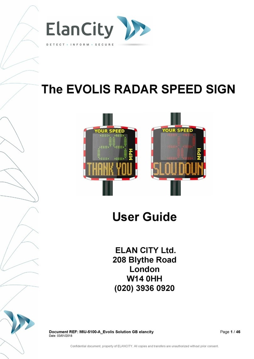
Elan City EVOLIS VISION User manual

Document reference: MI-0005-A_EVOLIS_VISION
Page 1of 25
Updated on: 09/03/2023
This document is the property of ELANCITY. It cannot be transferred to a third party without prior authorisation.
EVOLIS
VISION
INSTALLATION MANUAL

Document reference: MI-0005-A_EVOLIS_VISION
Page 2of 25
Updated on: 09/03/2023
This document is the property of ELANCITY. It cannot be transferred to a third party without prior authorisation.
1. PACKAGE CONTENTS .............................................................................................................................4
2. DESCRIPTION ........................................................................................................................................7
3. INSTALLATION......................................................................................................................................8
3.1 LOCATION ................................................................................................................................................. 8
3.2 INSTALLATION USING THE MOUNTING BAR ....................................................................................................... 9
3.3 POWER SUPPLY AND CONNECTIONS .............................................................................................................. 10
3.3.1 AC powered version .................................................................................................................... 11
3.3.2 Solar version................................................................................................................................ 11
3.3.3 Battery version............................................................................................................................ 12
3.4 CONNECT OPTION ..................................................................................................................................... 13
4. OPERATING YOUR SIGN....................................................................................................................... 14
4.1 STARTING UP ........................................................................................................................................... 14
4.2 SPEED LIMIT SELECTOR ............................................................................................................................... 15
5. MAINTENANCE.................................................................................................................................... 17
6. TECHNICAL DATA ................................................................................................................................ 18
7. TROUBLESHOOTING ............................................................................................................................ 20
8. SOFTWARE AND USER MANUALS ........................................................................................................ 22
8.1 EVOCOM/EVOGRAPH ................................................................................................................................ 22
8.2 EVOMOBILE ............................................................................................................................................. 22
9. CUSTOMER SERVICE ............................................................................................................................ 23
9.1 WARRANTY ............................................................................................................................................. 23
9.1.1 Delivery of goods ........................................................................................................................ 23
9.1.2 Retention of Ownership .............................................................................................................. 23
9.1.3 Warranty..................................................................................................................................... 24
9.1.4 Warranty disclaimer ................................................................................................................... 24
9.1.5 Returns Procedure....................................................................................................................... 24
9.1.6 Battery Warranty........................................................................................................................ 25
9.1.7 Terms and conditions of returns and reimbursement................................................................. 25
9.2 SPARE PARTS ........................................................................................................................................... 25
9.3 USER MANUALS /SOFTWARE ...................................................................................................................... 25
9.4 CERTIFICATE ............................................................................................................................................ 25

Document reference: MI-0005-A_EVOLIS_VISION
Page 3of 25
Updated on: 09/03/2023
This document is the property of ELANCITY. It cannot be transferred to a third party without prior authorisation.
Thank you for choosing the Evolis Vision radar speed sign. The sign will encourage drivers to slow down
by displaying:
- their speed,
- a flashing "danger" symbol for excessive speeds (optional),
- 5 (modifiable) messages according to their speed.
The system also records traffic statistics (option: average speeds, maximum speeds, number of
vehicles, distribution by speed range and percentiles, and data for one direction or both directions of
traffic).
Our Evocom/Evograph software is used to set up the system and download the statistics via USB cable
(standard), Bluetooth (standard), Smartphone/tablet (Evomobile app) and via a cellular connection
(optional Evoweb system).
This installation manual covers the following models:
Please note that depending on the model, some options may not be available
EVOLIS VISION
Displays speed and messages
EVOLIS MOBILITY
Displays speed but no messages.
EVOLIS VISION XL
Displays speed in large size numbers
but no messages
EVOLIS VISION OVER
Displays messages on top and speed
below.

Document reference: MI-0005-A_EVOLIS_VISION
Page 4of 25
Updated on: 09/03/2023
This document is the property of ELANCITY. It cannot be transferred to a third party without prior authorisation.
1. PACKAGE CONTENTS
Upon delivery, check the contents of the box against the packing list. You must report any errors or
damage incurred during transport to us within 2 working days.
The box should contain six items:
- The Evolis Vision radar speed sign,
- A vertical mounting bar,
- A USB cable (5m),
- This installation manual,
- The Bluetooth code to use on your product,
- A set of keys for the battery compartment.
During the 2-year warranty period, keep the original box and packaging
materials.

Document reference: MI-0005-A_EVOLIS_VISION
Page 5of 25
Updated on: 09/03/2023
This document is the property of ELANCITY. It cannot be transferred to a third party without prior authorisation.
Depending on the model, other accessories may be included:
AC power
- A set of male/female electrical connectors for connection to the electrical grid or street lighting,
- A 12V/22Ah battery.
Solar power
- A solar panel with the mounting kit,
- Two 12V/22Ah batteries.
Battery power
- An external battery charger,
- Two 12V/22Ah batteries.

Document reference: MI-0005-A_EVOLIS_VISION
Page 6of 25
Updated on: 09/03/2023
This document is the property of ELANCITY. It cannot be transferred to a third party without prior authorisation.
Dual power
- A set of male/female electrical connectors for connection to the electrical grid or street lighting,
- Two 12V/22Ah batteries.
- Optional when ordering:
oA solar panel with the mounting kit,
Batteries, solar panels, solar panel mounting kits and external chargers* are delivered separately.
Our batteries come charged and ready to use.
*The external charger is only supplied with the battery-powered version.
.

Document reference: MI-0005-A_EVOLIS_VISION
Page 7of 25
Updated on: 09/03/2023
This document is the property of ELANCITY. It cannot be transferred to a third party without prior authorisation.
2. DESCRIPTION
1
Two colour speed display (green/amber) + red
2
Message display (amber)
3
Battery holder
4
Clamps or straps (not included)
5
Battery compartments
6
Pre-programmed speed limit selector, waterproof USB connector
7
Electrical connector and solar connector for connection to the electrical grid or solar panel
(for devices equipped with the dual power option)
8
Solar cables for connection to the solar panel (for devices with the solar power option)

Document reference: MI-0005-A_EVOLIS_VISION
Page 8of 25
Updated on: 09/03/2023
This document is the property of ELANCITY. It cannot be transferred to a third party without prior authorisation.
3. INSTALLATION
Before installing your radar speed sign:
- Make sure you comply with local laws concerning work at height, and always ensure your own
safety and that of those around you.
- Also be sure to comply with local laws on road work signage.
- Mount the radar sign on a sturdy, stable pole of sufficient diameter. If in doubt, please contact
our sales department or customer service.
- Work on live electrical equipment requires certifications. Remember to comply with local laws
in this matter.
3.1 LOCATION
To get the best range, select the location of the radar based on the following criteria:
- Choose a straight section road with at least 400ft of unobstructed vision.This area and the radar
beam should be free of any objects (trees, poles, parked vehicles, other road signs…) as they
may disturb the radar's beam.
- Do not install your sign at intersections or on bridges. It should be at least 150 meters away
from cross traffic, since vehicles arriving from the side may be recorded as oncoming vehicles.
- The sign must be more than 65 meters away from large road signs, as they may interfere with
the radar beam.
- Verify that the radar sign does not block the visibility of existing road signs..
Traffic lane
Edge of the road
Between 3 and 9 ft
8ft

Document reference: MI-0005-A_EVOLIS_VISION
Page 9of 25
Updated on: 09/03/2023
This document is the property of ELANCITY. It cannot be transferred to a third party without prior authorisation.
- Ensure that the bottom edge of the radar sign is no lower than 240cms (app 8ft) and no higher
than 16ft from ground level. (too low : collision risk : pedestrians or cyclists).
- To avoid accidental collision, ensure that you leave a gap of at least 3ft between the radar
screen and the road. We recommend a gap of between 3ft and 9ft.
Horizontal
orientation
The Evolis Vision speed sign must be perpendicular to the road. Even if the
sign is placed at some distance from the road, it should not be tilted in either
direction, in order to maintain the maximum range.
Vertical
orientation
The sign must be installed straight, unless there is a very steep grade (+/- 5%). In
this case, the sign can be tilted up or down to match the angle of the grade by
placing a wedge behind the top or bottom of the mounting bar, so the radar beam
can "follow" the slope.
3.2 INSTALLATION USING THE MOUNTING BAR
A mounting bar is supplied with the radar sign. Strap the bar to a pole that is at least 90 mm in diameter
using clamps or straps (not included), in the correct orientation.
Insert the hooks on the back of the sign into the bar mounted on the pole. There is an eyehole where
you can install a padlock to further secure the sign. (Padlock not included).
For safety reasons, we strongly recommend using an aerial lift when installing the sign.
Installation recommendations
For solar powered signs, install the solar panel on the pole first before installing the radar sign.
(See solar panel manual supplied with the item)
1. Secure the mounting bar to the pole with the straps. (Caution: do not tighten completely so that
the sign position can still be adjusted)
2. Install the sign (without the batteries) on the mounting bar.
3. Adjust the position of the sign and fully tighten the pole straps.
4. Install the batteries, and/or connect the sign to the AC power supply.
For grades above 5%, please contact us..

Document reference: MI-0005-A_EVOLIS_VISION
Page 10 of 25
Updated on: 09/03/2023
This document is the property of ELANCITY. It cannot be transferred to a third party without prior authorisation.
Verification
Once the sign is installed, the range should be between 100 and 250 meters. The range can be
obstructed if the sign is not installed perpendicularly, or if there are obstacles, fog, etc.
3.3 POWER SUPPLY AND CONNECTIONS
Power supply
The Evolis Vision radar speed sign is powered by 12 volts and is designed to operate either:
- by connection to the electrical grid or the street lighting grid coupled with a 12V/22Ah
rechargeable battery,
- by solar panel with two rechargeable 12V/22Ah batteries,
- by two rechargeable batteries with external 12V/4A charger.
Power consumption
The Evolis Vision sign is protected against deep discharge of the batteries. Average power consumption
in watts of the Evolis Vision:
- Speed: 0.3A (3.6 watts at 12V),
- Speed + Message: 0.8A (9.6 watts at 12V),
- Standby: 0.1A (1.2 watts at 12V).
Safety system
The Evolis Vision has an intelligent protection process based on battery voltage:
- Critical limit 1: at 11.5V: The message display will shut off and the number display will switch to
lower brightness.
- Critical threshold 2: at 11.3V: The number display will shut off (two-coloured square displayed).
- Critical limit 3: at 11.1V: Sign switches to standby.
.
Electrical protection
An 8x32 8A time-delayed fuse is positioned at the battery output to protect the unit if the power
supply polarity is reversed. A second fuse located inside the box also protects the unit.
Please note that the EVOLIS VISION can only be used with a battery with a fuse-
protected connecting cable.

Document reference: MI-0005-A_EVOLIS_VISION
Page 11 of 25
Updated on: 09/03/2023
This document is the property of ELANCITY. It cannot be transferred to a third party without prior authorisation.
3.3.1 AC powered version
For recharging on the street lighting grid, the Evolis Vision is equipped with:
- An internal 8Ah charger,
- A 12V/22Ah lead battery,
- A set of IP68 male-female electrical connectors for connection to the grid.
When connecting the female connector, follow these instructions:
- Connect the neutral wire to the terminal marked "N"
- Connect the phase wire to the terminal marked "1"
- Connect the ground to the central terminal
We strongly recommend adding a 30mA calibre 16A type AC circuit
breaker between the mains current & the radar speed sign. ÉlanCité
cannot be held liable for damage caused by improper installation. If there
is no circuit breaker, the warranty will not apply if the internal electrical
charger fails.
3.3.2 Solar version
Ideally, the panel should face south. We recommend padlocking the unit through the eyehole at the
bottom.
Before connecting the solar panel to the sign, the battery must first be installed and connected to the
sign. The solar panel can be adjusted to the desired vertical angle.
Connect the solar panel cables to the sign cables.
Installation: Refer to the installation instructions provided with the solar panel.
The location must have a clear view of the sky for maximum charging capacity. Trees and buildings can
cast shadows on the solar panels, significantly reducing the performance of the solar cells.
Phase
1
Neutral
N
Ground
centre
25°-65°

Document reference: MI-0005-A_EVOLIS_VISION
Page 12 of 25
Updated on: 09/03/2023
This document is the property of ELANCITY. It cannot be transferred to a third party without prior authorisation.
3.3.3 Battery version
Mobile operation
For mobile use, the Evolis Vision is designed to operate with one or two batteries on a tripod for
occasional use or on a mast for semi-permanent use.
A single battery (without recharging) will power the sign for 3 to 8 days. For safety
reasons, do not move your Evolis Vision with the batteries inside, due to the total
weight of the unit.
When the two-coloured square appears on the Evolis Vision display (low battery warning), replace the
two batteries with charged ones.
A charged battery will gradually discharge even when not in use. To make sure you are
installing a fully-charged battery, remember to charge the battery before using it: connect
the battery terminals to the external charger we supplied and plug the power cable into the
220V wall socket.
Charge indicator
Solid red light
Charging is starting
Solid orange light
Charging in progress
Solid green light
Charging complete
It takes approximately 5 hours to fully charge the battery. The charging time may vary depending on the
remaining charge of the battery and the conditions under which the charging is performed. The battery
can be charged even when it is not completely discharged. The charging time indicated above
corresponds to the charging of a battery (supplied by us) discharged to 11.1V.

Document reference: MI-0005-A_EVOLIS_VISION
Page 13 of 25
Updated on: 09/03/2023
This document is the property of ELANCITY. It cannot be transferred to a third party without prior authorisation.
3.4 CONNECT OPTION
To activate the cellular Connect option on your sign you must first insert the Sim card into the
Connect module. Then open the back door of the sign and insert the module into the connector.

Document reference: MI-0005-A_EVOLIS_VISION
Page 14 of 25
Updated on: 09/03/2023
This document is the property of ELANCITY. It cannot be transferred to a third party without prior authorisation.
4. OPERATING YOUR SIGN
Before turning on your Evolis Vision radar speed sign, please read paragraph 9.8 concerning the
regulations in force in your country.
4.1 STARTING UP
As soon as it is powered on, the Evolis Vision performs a quick self-check:
1
Number display
188 in green
Number display LED test
2
Number display
# # # in green
Battery voltage test
(Example: 132 = 13.2 Volts)
Text display
INIT... in amber
Message test
3
Number display
8in red
Bluetooth test
4
Number display
1in green
Cellular and Bluetooth test
*only appears if you have installed the
Connect option.

Document reference: MI-0005-A_EVOLIS_VISION
Page 15 of 25
Updated on: 09/03/2023
This document is the property of ELANCITY. It cannot be transferred to a third party without prior authorisation.
4.2 SPEED LIMIT SELECTOR
For quick start-up, the common speed limits are already pre-programmed in the
sign.
Use the selector in the battery box to select the speed limit at the sign location.
Press the key to display the status of the product:
- "ON"
- "OFF"
- "Lb" low battery
- "SL" sleep mode
Press and hold the key to turn the sign on or off
Press the key while the sign is on to show the current setting
A long press of the button when the radar is turned on selects the speed setting
recorded on the radar.
The preset speeds will appear on the screen one by one, once the desired speed appears on
the screen release the button so that the speed is selected and taken into account by the
radar.

Document reference: MI-0005-A_EVOLIS_VISION
Page 16 of 25
Updated on: 09/03/2023
This document is the property of ELANCITY. It cannot be transferred to a third party without prior authorisation.
Evolis Vision pre-programmed settings
Speed
limit
selector
Description
Minimum
speed
triggering the
display
Speed
triggering a
colour change
Speed
triggering
flashing
numbers
Speed
triggering
danger
warning
symbol
Visual
20 mph
9 mph 21 mph 26 mph 31 mph
30 mph
9 mph 31 mph 36 mph 41 mph
50 mph
9 mph 51 mph 56 mph 51 mph
60 mph
9 mph 61 mph 66 mph 61 mph
70 mph
9 mph 71 mph 76 mph 71 mph
SP / 30 mph
9 mph 31 mph 36 mph 41 mph
* Text display not available on Mobility and Vision XL models
To change these settings, please refer to the Evocom software user manual.

Document reference: MI-0005-A_EVOLIS_VISION
Page 17 of 25
Updated on: 09/03/2023
This document is the property of ELANCITY. It cannot be transferred to a third party without prior authorisation.
5. MAINTENANCE
Batteries and solar panel
Make sure that the solar panel is not located in a shady area (under trees, near tall buildings, etc.), or
covered with snow or dust. Regularly clean the surface exposed to the sun and check the condition of
the batteries with a multimeter.
Electrical connection components, such as plugs, connectors, battery
cables, etc. can be replaced by a qualified electrician.
Vandalism
The Evolis Vision is designed to withstand minor vandalism just like road signs. For more significant
damage requiring repair or replacement, contact our customer service department for an appraisal
before repair.
Any damage to the external parts (such as the box, front panel, battery holder, mounting bar) must also
be repaired by qualified technicians.

Document reference: MI-0005-A_EVOLIS_VISION
Page 18 of 25
Updated on: 09/03/2023
This document is the property of ELANCITY. It cannot be transferred to a third party without prior authorisation.
6. TECHNICAL DATA
TECHNICAL DATA
POWER SUPPLY
Battery (Type, Voltage, Capacity) Lead; 12V; 22 Ah
Electric regulator 15 VDC; 8 A; 120 W
Solar panel 100 W
Dual power AC + Solar
UNIT & LOCK
Material (box) ABS / PC
Dimensions 766 x 708.5 x 161 mm
Weight
4.34 kg
Material (front face) UV resistant polycarbonate
Dimensions 760 x 702 x 2 mm
Packaging size 850 x 790 x 250 mm
Weight 9.2kg (solar) 9.6kg (hybrid)
Lock
Padlock on lower hook
DISPLAY
NUMBER DISPLAY
Dimension
Dim.: 490 x 399 mm
Colour
Red - Green
Quantity Green: 318 LEDs / Red: 402 LEDs
TEXT DISPLAY
Dimension Dim.: 160 x 320 mm
Colour Amber
Quantity 512 LEDs
COMMUNICATION
& CONNECTIVITY
Interface Lexan Digital
Bluetooth Bluetooth 5 Low Energy
PC EvoCom software
PC Operating system Windows 7 / 8 / 10 / 11
Smartphone EvoMobile mobile app
Phone OS iOS / Android

Document reference: MI-0005-A_EVOLIS_VISION
Page 19 of 25
Updated on: 09/03/2023
This document is the property of ELANCITY. It cannot be transferred to a third party without prior authorisation.
DETECTION
Antenna
Doppler IPS-937-F
Type of modulation
CW Doppler
Frequency
24.125 GHz
Maximum range
250 m (cars)
Speed tolerance
± 1 km/h
OPTION
Connect option
3G or 4G cellular connection
Relay option (dry contact and
controlled power supply)
External device (dry contact)
Flash lamp (controlled power supply)
GPS option Geolocation of the unit.
STANDARDS
EUROPE
Electromagnetic Compatibility
(EMC)
Directive 2014/53/EU
Exposure to electromagnetic fields
(EMF)
Directive 1999/519/EC
Radio Equipment (RED)
Directive 2014/53/EU
Treatment and recycling of
electronic products (WEEE)
Directive 2012/19/EU
Hazardous Substances in Electronic
Products (ROHS)
Directive 2011/65/EU
SOFTWARE &
APPLICATION
CONFIGURATION
Default settings
Custom settings
Message management
Display management
Calendar management
STATISTICS
Count (number of vehicles)
Speeds (maximum, average, etc.)
Data charts (percentiles, distribution,
etc.)
Statistics reports
STORAGE
16 MB
SUPERVISION
Hardware status
Health status
Memory available

Document reference: MI-0005-A_EVOLIS_VISION
Page 20 of 25
Updated on: 09/03/2023
This document is the property of ELANCITY. It cannot be transferred to a third party without prior authorisation.
7. TROUBLESHOOTING
Should you experience problems with your Evolis Vision, you can often find the solution in our
troubleshooting guide. Otherwise, please contact our customer service department.
Tools required
Symptom
Potential causes
Parts involved
No display at all
Power supply
Batteries / Electrical connectors
/ Solar panel
Solutions:
1. Turn the sign OFF and back ON and check the display self-test.
2. Try to connect to Evocom via USB or Bluetooth.
3. Check if the spy mode is enabled on Evocom. If it is enabled, disable it in the Settings tab.
4. Check the power supply to the unit by measuring the voltage at the battery, the solar panel, or the
220V street lighting power supply.
5. Check the fuse on the battery.
6. Check the condition of the external mobile connectors (PNC16 or male/female Maréchal
connectors).
Symptom
Potential causes
Parts involved
Detects vehicles late
Installation / Use
Topography / Configuration /
Settings
Solutions:
1. Check the installation of the unit.
2. Check the settings of the unit on Evocom
3. Move the unit if the location does not fully comply with our recommendations.
Table of contents
Other Elan City Radar manuals
Popular Radar manuals by other brands

SpotterRF
SpotterRF SP-POWER-1 quick start guide

MALA
MALA MIRA operating manual

Endress+Hauser
Endress+Hauser Micropilot FMR60 Functional safety manual
Garmin
Garmin GWX 68 installation guide

MPH Industries
MPH Industries ai.951689 installation guide

Endress+Hauser
Endress+Hauser Micropilot FMR60 technical information
