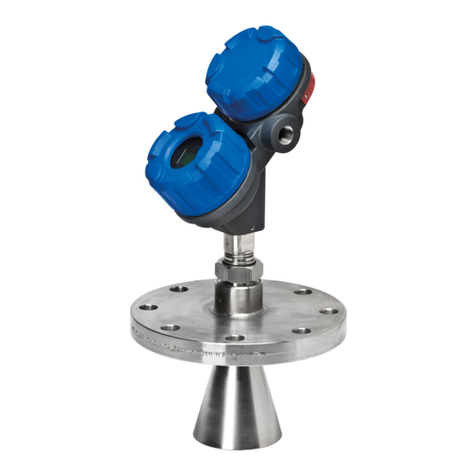
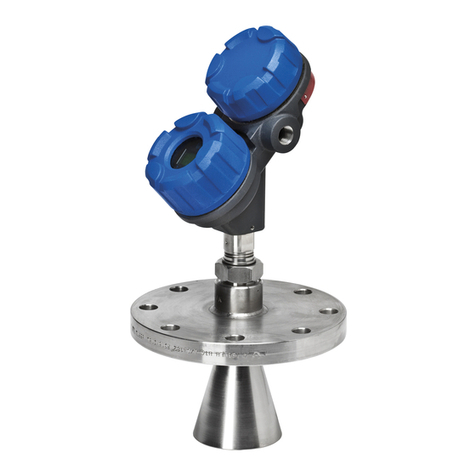
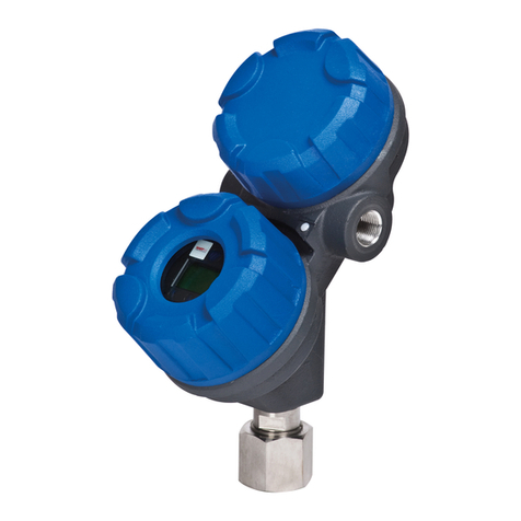
Magnetrol R82 User manual

Pulse Burst Radar
Level Transmitter
Installation and Operating Manual
Model R82
R82 software v1.0a
PRELIMINARY

Read this Manual Be ore Installing
This manual provides information on the R82 Radar transmitter. It is
important that all instru tions are read arefully and followed in
sequen e. The QuickStart Installation instru tions are a brief guide to
the sequen e of steps for experien ed te hni ians to follow when
installing the equipment. Detailed instru tions are in luded in the
Co plete Installation se tion of this manual.
Conventions Used in this Manual
Certain onventions are used in this manual to onvey spe ifi types of
information. General te hni al material, support data, and safety
information are presented in narrative form. The following styles are
used for notes, autions, and warnings.
NOTES
Notes ontain information that augments or larifies an operating
step. Notes do not normally ontain a tions. They follow the pro-
edural steps to whi h they refer.
Cautions
Cautions alert the te hni ian to spe ial onditions that ould injure
personnel, damage equipment, or redu e a omponent’s me hani-
al integrity. Cautions are also used to alert the te hni ian to unsafe
pra ti es or the need for spe ial prote tive equipment or spe ifi
materials. In this manual, a aution box indi ates a potentially haz-
ardous situation whi h, if not avoided, may result in minor or
moderate injury.
WARNINGS
Warnings identify potentially dangerous situations or serious haz-
ards. In this manual, a warning indi ates an imminently hazardous
situation whi h, if not avoided, ould result in serious injury or
death.
Sa ety Messages
The Through-Air Radar system is designed for use in Category II,
Pollution Degree 2 installations. Follow all standard industry pro e-
dures for servi ing ele tri al and omputer equipment when working
with or around high voltage. Always shut off the power supply before
tou hing any omponents. Although high voltage is not present in this
system, it may be present in other systems.
Ele tri al omponents are sensitive to ele trostati dis harge. To pre-
vent equipment damage, observe safety pro edures when working with
ele trostati sensitive omponents.
Low Voltage Directive
For use in Installations Category II, Pollution Degree 2. If equipment
is used in a manner not spe ified by the manufa turer, prote tion pro-
vided by equipment may be impaired.
NOTE: This equipment has been tested and found to omply with
the limits for a Class B digital devi e, pursuant to Part 15 of the
FCC Rules. These limits are designed to provide reasonable prote -
tion against harmful interferen e in a residential installation. This
equipment generates, uses and an radiate radio frequen y energy
and, if not installed and used in a ordan e with the instru tions,
may ause harmful interferen e to radio ommuni ations. However,
there is no guarantee that interferen e will not o ur in a parti ular
installation. If this equipment does ause harmful interferen e to the
radio or television re eption, whi h an be determined by turning
the equipment off and on, the use is en ouraged to try to orre t the
interferen e by one or more of the following measures:
•Reorient or relo ate the re eiving antenna.
• In rease the separation between the equipment and re eiver.
• Conne t the equipment into an outlet on a ir uit different from
that to whi h the re eiver is onne ted.
• Consult the dealer or an experien ed radio/TV te hni ian for
help.
Any unauthorized hanges or modifi ations not expressly approved by
Magnetrol International, In orporated ould void user’s authority to
operate this equipment.
WARNING! Explosion hazard. Do not onne t or dis onne t designs
rated Explosion-proof or Non-in endive unless power has been
swit hed off and/or the area is known to be non-hazardous
Notice o Copyright and Limitations
Magnetrol & Magnetrol logotype are registered trademarks of
Magnetrol International.
Copyright © 2009 Magnetrol International, In orporated
All rights reserved.
Performan e spe ifi ations are effe tive with date of issue and are sub-
je t to hange without noti e. Magnetrol reserves the right to make
hanges to the produ t des ribed in this manual at any time without
noti e. Magnetrol makes no warranty with respe t to the a ura y of the
information in this manual.
Warranty
All Magnetrol ele troni level and flow ontrols are warranted free of
defe ts in materials or workmanship for one full year from the date of
original fa tory shipment.
If returned within the warranty period; and, upon fa tory inspe tion of
the ontrol, the ause of the laim is determined to be overed under
the warranty; then, Magnetrol will repair or repla e the ontrol at no
ost to the pur haser (or owner) other than transportation.
Magnetrol shall not be liable for misappli ation, labor laims, dire t or
onsequential damage or expense arising from the installation or use of
equipment. There are no other warranties expressed or implied, ex ept
spe ial written warranties overing some Magnetrol produ ts.
Quality Assurance
The quality assuran e system in pla e at Magnetrol guarantees the
highest level of quality throughout the ompany. Magnetrol is
ommitted to providing full ustomer satisfa tion both in quality
produ ts and quality servi e.
Magnetrol’s quality assuran e system is registered
to ISO 9001 affirming its ommitment to known
international quality standards providing the
strongest assuran e of produ t/servi e quality
available.
58-610 Model R82 Radar Transmitter
Table of Contents
1.0 QuickStart Installation
1.1 Getting Started..........................................................4
1.1.1 Equipment and Tools .....................................4
1.1.2 Configuration Information.............................5
1.2 Qui kStart Mounting................................................6
1.2.1 Transmitter/Antenna ......................................6
1.3 Qui kStart Wiring ....................................................6
1.4 Qui kStart Configuration .........................................7
2.0 Complete Installation
2.1 Unpa king ................................................................9
2.2 Ele troni Dis harge (ESD) Handling Pro edure......9
2.3 Before You Begin.....................................................10
2.3.1 Site Preparation ............................................10
2.3.2 Equipment and Tools ...................................10
2.3.3 Operational Considerations..........................10
2.3.3.1 Maximum Distan e...............................10
2.3.3.2 Minimum Distan e...............................10
2.3.3.3 Problemati Appli ations;
GWR Alternative ..................................11
2.4 Mounting................................................................12
2.4.1 Installing the Antenna ..................................12
2.4.1.1 Lo ation................................................12
2.4.1.2 Beam Angle...........................................12
2.4.1.3 Obstru tions .........................................13
2.4.1.4 Nozzles..................................................13
2.4.1.5 Standpipes and Stillwells .......................14
2.4.2 Installing the Transmitter .............................14
2.4.2.1 Orientation ...........................................14
2.4.2.2 Initial Installation..................................15
2.4.2.3 Poor Signal Quality...............................15
2.5 Wiring ....................................................................16
2.5.1 General Purpose or Non-In endive ..............16
2.6 Configuring the Transmitter....................................17
2.6.1 Operating Parameters ...................................17
2.6.2 Setting Up for Shop Configuration ..............17
2.6.3 Transmitter Display and Keypad ..................17
2.6.4 Menu Traversal .............................................18
2.6.4.1 Navigating Menu.....................................18
2.6.4.2 Entering Chara ter Data .........................18
2.6.4.3 Entering numeri data using Digit Entry 19
2.6.4.4 Entering numeri data using
In rement/De rement .............................19
2.6.5 Password Prote tion (Default = 0)................20
2.6.6 Menu: Step-By-Step Pro edure.....................21
2.6.5.1 Radar Transmitter User Menu ..............22
2.6.5.2 Radar Transmitter Fa tory Menu ..........26
2.6.7 HART Menu................................................27
3.0 Re erence In ormation
3.1 Des ription .............................................................29
3.2 Theory of Operation...............................................29
3.2.1 Pulse Burst Radar .........................................29
3.2.2 Equivalent Time Sampling ...........................30
3.3 Troubleshooting ......................................................31
3.3.1 System Problems ..........................................31
3.3.2 Error Messages .............................................32
3.4 Agen y Approvals....................................................35
3.4.1 Agen y Drawing and Entity Parameters .......36
3.5 Parts ........................................................................37
3.5.1 Repla ement Parts ........................................37
3.5.2 Re ommended Spare Parts ...........................37
3.6 Spe ifi ations ..........................................................38
3.6.1 Fun tional – Transmitter ..............................38
3.6.2 Performan e .................................................39
3.6.3 Fun tional ....................................................40
3.6.4 Antenna Pressure/Temperature Ratings ........40
3.6.5 Physi al ........................................................41
3.7 Model Numbers......................................................36
3.7.1 R82 Radar Transmitter.................................42
Glossary .........................................................................43
Model R82 Con iguration Data Sheet ..........................46
R82 Pulse Burst Radar Level Transmitter
58-610 Model R82 Radar Transmitter
4
1.0 QuickStart Installation
The Qui kStart Installation pro edures provide the key
steps for mounting, wiring, and onfiguring the R82 radar
level transmitter. These pro edures are intended for experi-
en ed installers of ele troni level measurement instruments.
See Complete Installation, Se tion 2.0, for detailed installa-
tion instru tions.
1.1 Getting Started
Before beginning the Qui kStart Installation pro edures,
have the right equipment, tools, and information available.
1.1.1 Equipment and Tools
No spe ial tools are needed. The following items are
re ommended:
• Threaded antenna and transmitter . . . . . . 2" (50 mm)
• Flat-blade s rewdriver
• Digital multimeter or volt/ammeter . . . . . Optional
• 24 VDC (23 mA) power supply. . . . . . . . Optional
58-610 Model R82 Radar Transmitter
5
1.1.2 Configuration Information
Some key information is needed to onfigure the R82 radar
transmitter. Complete the following operating parameters
table before beginning onfiguration.
NOTE: The transmitter will already be configured if this information was
provided with the order.
Display Question Answer
Units What units of measurement will be
used? _____________
Will the unit measure in Level or
Volume? _____________
What are the Volume units? _____________
What is the relationship between Level
and Volume? (Enter up to 20 points) _____________
Sensor What is the distance from the top (100%)
Offset of the tank and the Sensor Reference
point (bottom of NPT thread, top of SP
thread, or face of flange?) _____________
Tank Top Is the Tank Top Flat, Horizontal Cylinder,
Dome, Irregular or other (non-metallic)? _____________
Tank What is the tank height? _____________
Height NOTE: Sensor Offset + Tank Height =
Distance from process
connection to tank bottom
locking What is the distance from Sensor
Distance Reference point to Maximum Level?
Maximum level should never be less
than 15" (375 mm) from the bottom of the
process connection (threaded or flanged). _____________
Level Is there a region at the very bottom of the
Offset vessel that cannot be measured due to
heating coils, angle tank bottom, etc.? _____________
Dielectric What is the dielectric of the process
medium? _____________
Turbulence Is turbulence a consideration? _____________
Foam Will there be foam on the surface? _____________
Rate of What is the maximum rate the level
Change will rise or fall? _____________
4.0 mA What is the 0% reference point for the
Setpoint 4.0 mA value? _____________
20.0 mA What is the 100% reference point for
Setpoint the 20.0 mA value? _____________
58-610 Model R82 Radar Transmitter
Other manuals for R82
1
Table of contents
Other Magnetrol Radar manuals

Magnetrol
Magnetrol Pulsar R96 User manual

Magnetrol
Magnetrol Eclipse 705-51A Series User guide

Magnetrol
Magnetrol eclipse 705 User guide

Magnetrol
Magnetrol Pulsar R86 User manual

Magnetrol
Magnetrol Pulsar Foundation fieldbus R96 User manual

Magnetrol
Magnetrol Pulsar R86 User manual

Magnetrol
Magnetrol pulsar RX5 User manual