Magnum Energy ME-PT1 User manual

ME-PT1 Instruction Sheet
Part Number: 64-0025 Rev B 1
Magnum Energy, Inc.
2211 West Casino Rd.
Everett, WA, USA 98204
www.magnumenergy.com
Introduction
The ME-PT1 (pigtail one-wire) adapter connects to Magnum’s Auto Generator
Start (ME-AGS) controller to allow the connected generator to start when an
external +12-volt DC supply is applied. This is useful for applications in which
there is a need to automatically turn the generator on/off externally, either
through a manually controlled switch or from an automatically controlled
switching device.
When +12-volts is supplied to this pigtail wire it causes the AGS controller to
start and run the connected generator.
Info: The high temperature start feature on the AGS is not available
when using the ME-PT1. However, the low battery voltage start
feature is still available.
Installation/Setup – ME-AGS-N (Network Version)
The following pertains to the ME-PT1 when connected to the ME-AGS-N.
Info: Refer to the ME-AGS-N Owner’s Manual (64-0039) for
installation, setup, and operation of the ME-AGS-N; and to the ME-
RC (64-0003) or ME-ARC owner’s manuals (64-0030) for information
on selecting/adjusting settings.
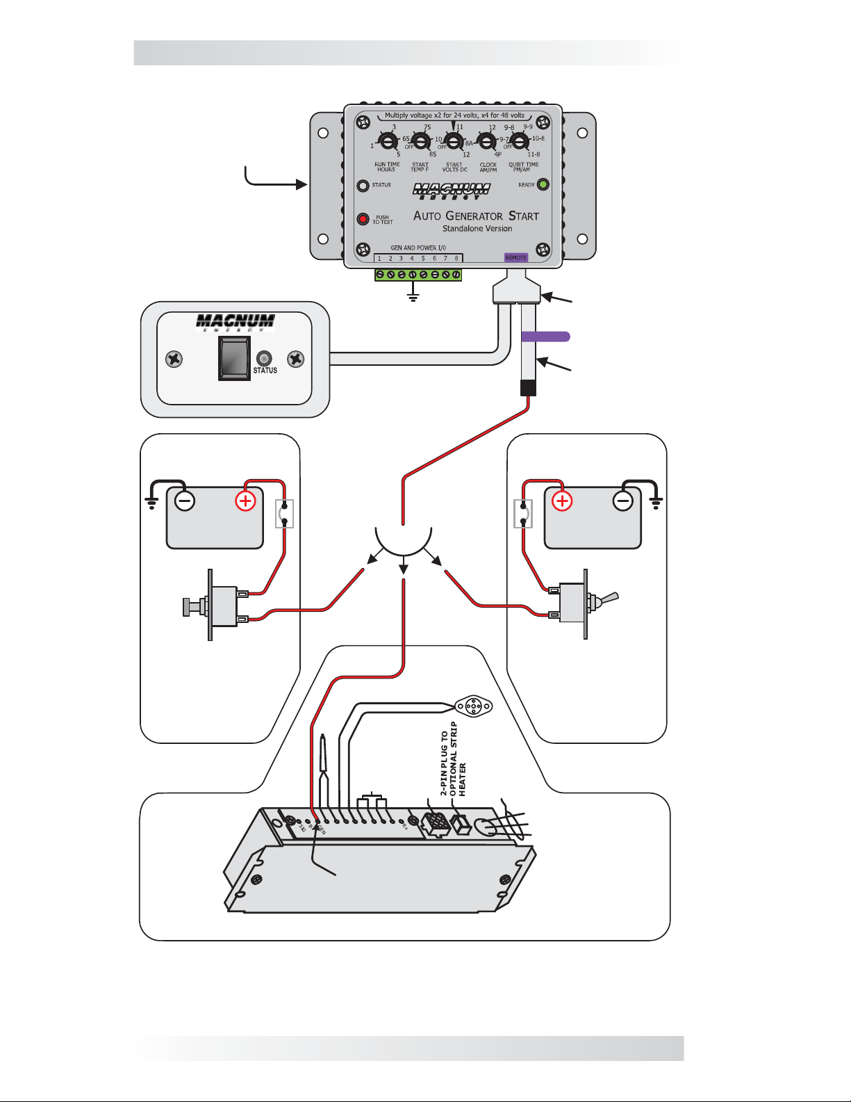
Installation
To install the ME-PT1, refer to Figure 1 and the steps below:
1. Connect the red wire on the ME-PT1 adapter to a +12-volt DC external
switching device (i.e., switch).
2. Plug the ME-PT1 adapter into the REMOTE (purple) port on the ME-AGS-N.
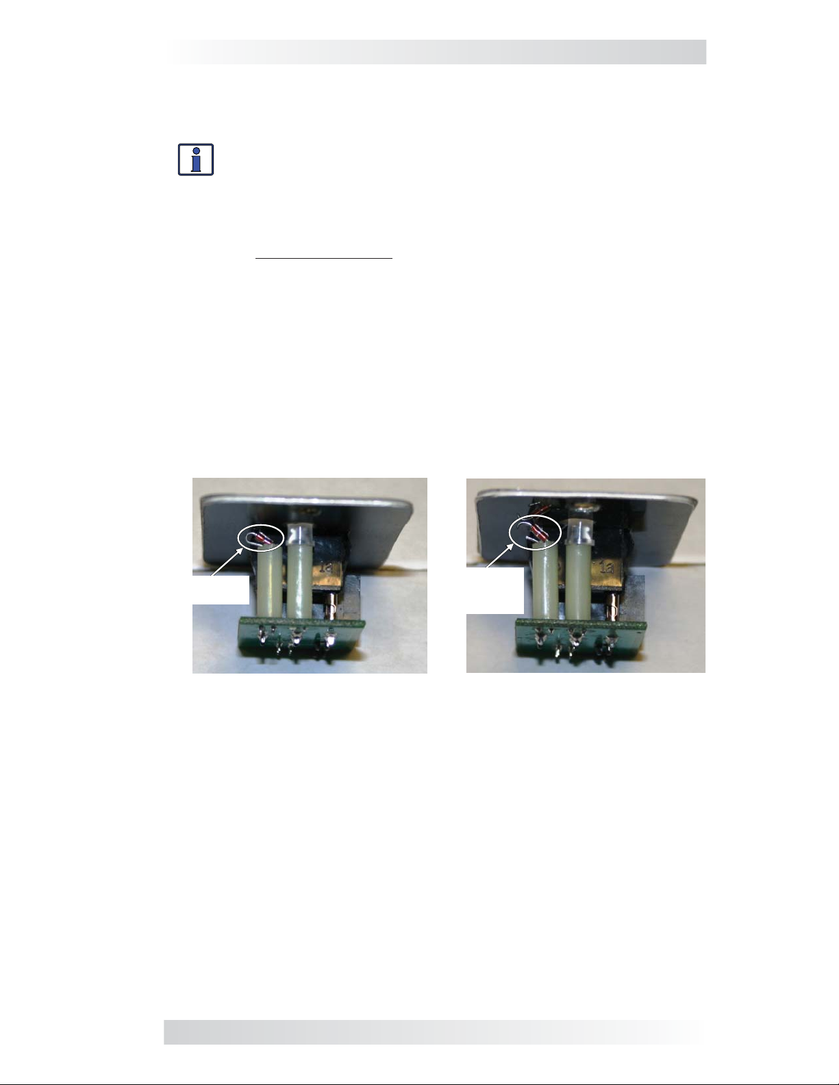
Info: The remote temperature sensor that comes with the
ME-AGS-N (normally plugged into the AGS’s REMOTE port) is not
used when a ME-PT1 is connected.
Setup
When using the ME-PT1 with the ME-AGS-N, configure the ME-RC (or ME-
ARC) to allow the ME-AGS-N to accept the external input from the ME-PT1.
• Find the temperature start setting—depending on your remote: ME-RC
(under AGS/04 Start Temp F menu), or ME-ARC (under SETUP/04E Gen
Run Temp/Start menu). Then, select the Start=Ext Input setting.
ME-PT1 to ME-AGS-N Operation
The type of external switch (i.e., “momentary” or “maintain”) connected to
the ME-PT1 adapter determines how long the generator can run.
ME-RC
A. Using a momentary type switch: Pressing the switch causes the generator
to run for the duration of a full run time cycle (as set in the AGS/03 Run Time
Hour menu), and then stop.
B. Using a maintain type switch: If the switch is set to ON, the generator
continues to run until the switch is set to OFF. Once the switch is set to OFF,
the generator will continue to run for the remaining duration of the current
run time cycle (as set in the AGS/03 Run Time Hour menu), and then stop.

ME-PT1 Instruction Sheet
2 © 2014 Magnum Energy, Inc.
Figure 1, ME-PT1 to ME-AGS-N Installation
12-volt
DC supply
fuse
12-volt
DC supply
fuse
ME-AGS-N
External
Maintain Switch
External
Momentary Switch
ME-RC One time push
(or close): gen runs
for duration of run
time cycle, then stops.
ME-ARC Press switch:
gen runs for 2
minutes, then stops.
Coleman Air Conditioner Zone Control Box
ON
OFF
ME-ARC Switch set
to ON: gen runs until
switch set to OFF.
Switch set to OFF:
gen runs for 2 mins.,
then stops.
ME-RC Switch set to
ON: gen runs until
switch set to OFF.
Switch set to OFF: gen
runs for remaining
duration of run time
cycle, and then stops.
options
PT1-AGS
To Network port on
Magnum inverter
All grounds must be bonded
together to ensure the ME-PT1
works correctly
GEN connection
provides +12VDC
from Zone Control
Box when gen
needs to start.
GEN
connection
GR EE N (GN D)
WHITE (L2)
BLA CK (L1)
ZONE CONTROL BOX
115 VAC IN
9-PIN PL UG TO
UPPER UNIT
FREEZE ROOM HEAT
SHED COOL
SHED
TO USE WITH
LOAD SHED
DEVI CE R EM OVE
JUMPER AND
CONNECT TO
N.C. CONTATCT
ROOM
SENSOR
FR EEZE SENSOR
ME-PT1
ME-ARC
A. Using a momentary type switch: Pressing the switch causes the generator
to run for two minutes, and then stop.
B. Using a maintain type switch: If the switch is set to ON, the generator
continues to run until the switch is set to OFF. Once the switch is set to OFF,
the generator will run for two minutes, and then stops.

ME-PT1 Instruction Sheet
© 2014 Magnum Energy, Inc. 3
Installation/Setup – ME-AGS-S (Standalone Version)
The following pertains to the ME-PT1 when connected to the ME-AGS-S
(Standalone Version) controller.
Info: Other than the specific installation and setup instructions
listed below, refer to the ME-AGS-S Owner’s Manual (64-0004) for
installation, setup, and operation of the ME-AGS-S.
Installation
To prepare the ME-AGS-S remote switch:
1. Find the temperature sensor behind the remote switch’s front plate. It is a
small reddish looking device close to the metal front plate (see Figure 2).
2. Use a pair of small wire cutters to cut open one side of the temperature
sensor wire (see Figure 3). Ensure the cut ends are not able to touch.
To install the
ME-PT1 (
refer to the steps below and Figure 4):
1. Plug a 6-conductor phone splitter into the REMOTE (purple) port on the
ME-AGS-S controller.
2. Plug the ME-PT1 adapter into one of the phone splitter’s ports, and
then plug the remote switch—using its communications cable—into the
phone splitter’s other port.
3. Connect the red wire on the ME-PT1 adapter to a +12-volt DC external
switching device (i.e., switch).
Temperature
Sensor Temperature
Sensor
(cut open)
Figure 2, Locating Sensor Figure 3, Sensor Cut Open
Setup
1. On the ME-AGS-S, turn the START TEMP F adjustment clockwise to any
temperature position (DO NOT turn counterclockwise to OFF position).
2. Press the remote switch on the ME-AGS-S to the up (ENABLE) position.
ME-PT1 to ME-AGS-S Operation
The type of external switch (i.e., “maintain” or “momentary”) connected to
the ME-PT1 adapter determines how long the generator can run.
A. Using a momentary type switch: Pressing the switch causes the generator
to run for the duration of the RUN TIME HOURS period, and then stop.
B. Using a maintain type switch: If the switch is set to OFF, the generator
stays off. If the switch is set to ON, the generator runs until the switch is set
to OFF. Once the switch is set to OFF, the generator will not stop until the
current RUN TIME HOURS cycle has been satisfied.

ME-PT1 Instruction Sheet
4 © 2014 Magnum Energy, Inc.
Figure 4, ME-PT1 to ME-AGS-S Installation
12-volt
DC supply
fuse
12-volt
DC supply
fuse
External
Maintain Switch
External
Momentary Switch
One time push (or
close): Gen runs for
duration of RUN TIME
HOURS period.
Coleman Air Conditioner Zone Control Box
ON
OFF
ON: Gen continues
to run.
OFF: Gen stops
once current RUN
TIME HOURS cycle
has been satisfied.
options
GEN connection
provides +12VDC
from Zone Control
Box when gen needs
to start.
GEN
connection
GR EE N (GN D)
WHITE (L2)
BLA CK (L1)
ZONE CONTROL BOX
115VAC IN
9-PIN PL UG TO
UPPER UNIT
FREEZE ROOM HEAT
SHED COOL
SHED
TO USE WITH
LOAD SHE D
DEVI CE R EM OVE
JUMPER AND
CONNECT TO
N.C. CONTATCT
ROOM
SENSOR
FR EEZE S ENS OR
PT1-AGS
Phone Splitter
(6-conductor)
ME-AGS-S
Remote Switch
(with Temp Sensor opened)
All grounds must be
bonded together to
ensure the ME-PT1
works correctly
ME-PT1
AUTO GEN START
ENABLE
OFF
TEST
Other Magnum Energy Adapter manuals