1.3 DATASHEET
www.magtrol.comDATASHEET
Page 1 / 11©2020 MAGTROL | Due to continual product development, Magtrol reserves the right to modify specifications without forewarning.
TM SERIES
TM
SERIES
IN-LINE TORQUE TRANSDUCERS
FEATURES
▪Integrated torque and speed conditioning
▪Torque Range: from 0.1N·m to 10 kN·m
(0.07 lb·ft to 7375 lb·ft)
▪Accuracy: < 0.1 %
▪Overload Capacity: 200 %
▪Breaking Limit: > 400 %
▪High Speed Applications: up to 50 000 rpm
▪Non-Contact (no sliprings)
▪No Electronic Components in Rotation
▪High Electrical Noise Immunity
▪Single DC Power Supply: 20 VDC to 32 VDC
▪Immediate Speed Detection
▪Adjustable Torque Signal Frequency
Pass Band up to 5 kHz
▪Built-In Test Function (B.I.T.E.)
▪Stainless Steel Shaft
▪EMC Susceptibility Conforms to
European Standards
DESCRIPTION
Magtrol’s In-Line Torque Transducers provide extremely
accurate torque and speed measurement over a very broad
range. Each model has an integrated conditioning electronic
module providing a 0 VDC to ± 10 VDC torque output and an
open collector speed output. Magtrol Torque Transducers are
very reliable, providing high overload protection, excellent long
term stability and high noise immunity.
All transducer models employ our unique non-contact
differential transformer torque measuring technology. This
measuring technology offers many benefits, most notably that
no electronic components rotate during operation.
To provide customers with several price/performance options,
Magtrol offers three torque transducer models: basic model
(TMB Series), high accuracy (TM Series) and high speed with
high accuracy (TMHS).
Each transducer consists of a hardened stainless steel shaft
with smooth, splined or keyway shaft ends, an anodized
aluminium housing containing the guide bearings and an
electronic measurement conditioner.
The integrated electronic circuit, supplied by single DC
voltage, provides torque and speed signals without any
additional amplifier. The transducer is a stand-alone
measuring chain. Connections are made by means of a
6-pole male connector mounted on the housing. A removable
aluminium base (delivered as standard with TM and TMHS
models, and as an option for TMB transducers) allows fixed
mounting of the transducer.
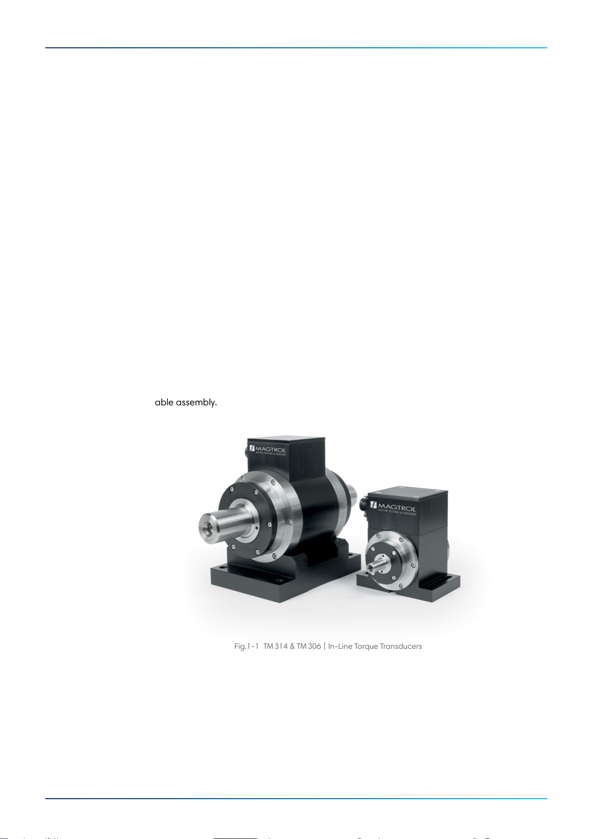
Fig. 1: TM 312 & TM 308 In-Line Torque
Transducer with smooth shaft
www.magtrol.comDATASHEET
Page 2 / 11©2020 MAGTROL | Due to continual product development, Magtrol reserves the right to modify specifications without forewarning.
TM SERIES
OPERATING PRINCIPLES
The measuring system, based on the principle of a variable,
torque proportional transformer coupling, consists of two
concentric cylinders shrunk on the shaft on each side of the
shaft’s deformation zone, and two concentric coils attached
to the housing.
Both cylinders have a circularly disposed coinciding row of
slots and rotate with the shaft inside the coils. An alternating
current with the frequency of 20 kHz flows through the primary
coil. When no torque is applied, the slots on the two cylinders
fail to overlap. When torque is applied, the deformation zone
undergoes an angular deformation and the slots begin to
overlap.
Thus a torque-proportional voltage is on the secondary
coil. The conditioning electronic circuit incorporated in the
transducer converts the voltage to a nominal torque signal of
0VDC to ± 5VDC. A low-pass filter (Butterworth / 2nd order),
adjustable from 5 kHz to 1 Hz, allows tuning of the torque
signal frequency limitation.
An optical sensor reads the speed on a toothed pattern
machined directly on the measuring system. The electronic
conditioner outputs a frequency signal proportional to the shaft
rotational speed. An active circuit compensates the zero and
sensitivity temperature drifts within a tolerance of 0.1 % / 10 K.
APPLICATIONS
TM, TMB and TMHS Series Torque Transducers provide
dynamic torque and speed measurement of:
▪Propellers - aerospace, marine and helicopter
▪Windshield wipers, electrical windows, starters,
generators and brakes in automobile industry
▪Pumps - water and oil
▪Reduction gears and gearboxes
▪Clutches
▪Motorized valves
▪Drills, pneumatic tools and other machine tools
SYSTEM CONFIGURATION
ELECTRICAL CONFIGURATION
SUPPORTED & SUSPENDED
INSTALLATIONS
TheTMB Series is dedicated for use in a basic configuration
or for low speed applications. The TMB Series ranges from
TMB 304 (1 N·m) to TMB 313 (500 N·m). Due to dedicated
low speed usage,the TMB Series is delivered without base
mount however, a base is available as an option.
The TM Series ranges from TM 309 to TM 317 and can
also be installed without the base mount in a suspended
configuration. This configuration is only allowed for low
speed measurment. The benefit of this configuration is the
use of a single element coupling, creating a shorter drive train.
TM Series
Torque Transducer
MODEL 3411
Torque Display
Computer with
TORQUE Software
Fig. 2: TM connected with MODEL3411 Torque Display and a
computer with TORQUE Software
Power Supply
20 to 32 VDC / 100 mA (max.)
Test
Torque 0 to ±10 VDC (max.)
Speed
Fig. 3: TM's electrical input and output
Fig. 4: Supported installation
Mandatory for standard and high speed applications
Fig. 5: Suspended installation for low speed application only.
Use single element coupling to create a shorter drive train.
2agtrol.co
TM seriesINTRODUCTION