MAHA Maschinenbau Haldenwang MPM-4M User manual

Fehler! Verwenden Sie die Registerkarte 'Start', um Name dem Text zuzuweisen, der hier angezeigt
werden soll.Fehler! Verwenden Sie die Registerkarte 'Start', um Name dem Text zuzuweisen, der hier
angezeigt werden soll.Fehler! Verwenden Sie die Registerkarte 'Start', um Name dem Text
zuzuweisen, der hier angezeigt werden soll.
MPM-4M
Particle Measurement Unit
Original Operating Instructions
BA314001-en

2
BA314001-en
Contents
1Safety.......................................................................................................................3
1.1Introduction ........................................................................................................................................... 3
1.2Symbols ................................................................................................................................................ 3
1.3Intended Use ........................................................................................................................................ 3
1.4Safety Instructions for Operation .......................................................................................................... 3
1.5Safety Instructions for Servicing ........................................................................................................... 4
2Description ..............................................................................................................4
3Initial Operation.......................................................................................................6
3.1Unpacking............................................................................................................................................. 6
3.2Instrument Setup .................................................................................................................................. 6
3.3Power Supply........................................................................................................................................ 6
3.4Sample In.............................................................................................................................................. 7
3.5Sample Out........................................................................................................................................... 7
3.6RS 232 Output ...................................................................................................................................... 7
3.7Analog Output (when installed) ............................................................................................................ 7
3.8Remote Control (Optional).................................................................................................................... 8
4Operation.................................................................................................................9
4.1Warm up ............................................................................................................................................... 9
4.2Auto-Zero Adjust................................................................................................................................... 9
4.3Test Selection ..................................................................................................................................... 10
4.4Stall Test............................................................................................................................................. 11
4.5Free Acceleration Test ....................................................................................................................... 12
4.6Continuous Measurement .................................................................................................................. 15
5Calibration .............................................................................................................16
6Maintenance ..........................................................................................................18
6.1Checking and Replacing the Rear Panel Filter .................................................................................. 18
6.2Checking and Replacing the Internal Filter ........................................................................................ 19
7Disposal.................................................................................................................19
8Annex.....................................................................................................................20
9Company Information...........................................................................................23

3
BA314001-en
1 Safety
1.1 Introduction
Thoroughly read this manual before operating the equipment and comply with the instructions.
Always display the manual in a conspicuous location.
Personal injury and property damage incurred due to non-compliance with these safety
instructions are not covered by the product liability regulations.
1.2 Symbols
Important safety instructions. Failure to comply with instructions could result in personal injury or
property damage.
Important information.
1.3 Intended Use
This equipment is designed to measure the concentration of fine particulate matter in the
exhaust of diesel engines.
The equipment shall not be modified without the express written consent of the manufacturer. In
case of non-compliance the declaration of conformity becomes void.
Any use other than described is inappropriate.
1.4 Safety Instructions for Operation
The accident prevention regulations of the country in which the Particle Measurement Unit is
being operated apply.
The Particle Measurement Unit may not be installed and operated in hazardous locations or
washing bays.
The Particle Measurement Unit may only be used for its intended purpose and within its stated
performance limits.
The Particle Measurement Unit may only be operated by trained personnel.
All parts of the Particle Measurement Unit must be protected from moisture and corrosive
substances.
The Particle Measurement Unit and the surrounding work area must be kept clean.
Running vehicle engines in closed rooms represent potential carbon monoxide poisoning. The
operator/owner is responsible for providing sufficient air ventilation.

4
BA314001-en
1.5 Safety Instructions for Servicing
Repair work of any kind (other than routine servicing expicitly covered in this operator manual)
may only be done by authorized service technicians. In case of non-compliance the warranty
becomes void.
2 Description
The MPM 4M is a self-contained maintenance tool which continuously measures the
concentration of fine particulate matter (PM) in the exhaust of diesel engines, using
standardized tests developed in joint government/mining industry projects.
The measurement principle is based on well-established laser light-scattering technologies,
which are widely accepted and used for measurement of particle concentrations in numerous
laboratory and industrial applications. The MPM-4 takes this technology several steps further,
by adding sophisticated automated data processing capabilities and by ruggedizing the design
to withstand the harsh operating conditions. Simple and accessible user maintenance greatly
reduces the need for inconvenient “back-to-base” servicing.
Ensuring the accuracy and consistency of measurement is vitally important. As well as
performing an auto-zero at the start of each test, the instrument’s calibration can be checked by
the operator in less than a minute, using the supplied calibration device.
User-maintainability is also a high priority. If a particularly dirty or wet sample is ingested and
the instrument’s response is degraded because of dirt on the optical elements, both the laser
module and/or the detector head can be removed in seconds, without tools.
Both of these items can be quickly cleaned, using the same cleaning solution and polishing
cloth used for spectacle cleaning. In this situation, previous examples of this type of instrument
would require service at the manufacturer or distributor, including possible replacement of
expensive components.
The MPM-4M design ensures that both the laser and the detector are not only readily acces-
sible, but importantly are also positively and repeatably aligned upon re-insertion, without affec-
ting the instrument calibration. This can be confirmed using the supplied calibration device.
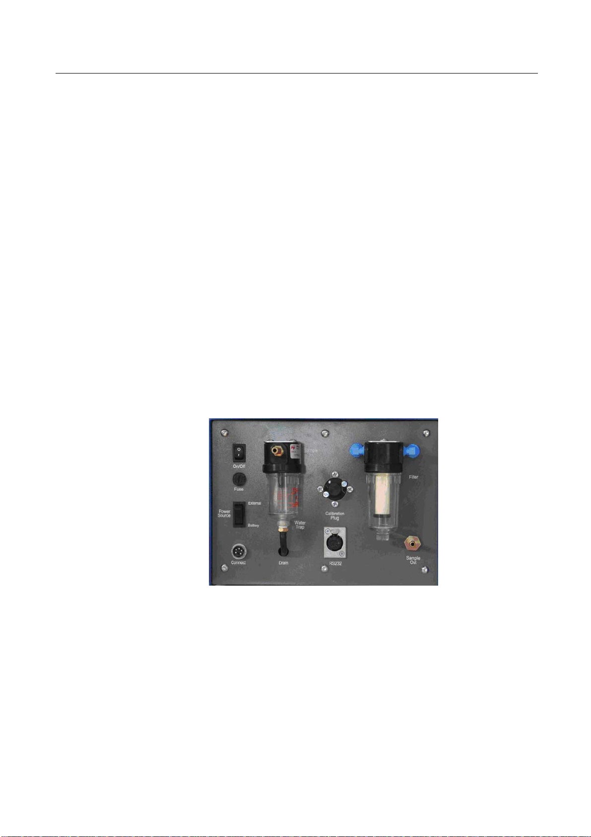
A single HEPA grade filter is used to remove over 99.9% of particles before releasing the mea-
sured sample stream into the atmosphere. The filter unit is a standard screw-off housing design
with a disposable filter element. No tools are required to change the filter element. A second
disposable HEPA filter is located inside the case to continuously filter a stream of ambient air
which protects the optical elements from contamination by soot or moisture in the sample.
Added protection for the measuring system is provided by an automatic drain pump, which
operates every 60 seconds to remove any accumulated condensate from the water trap.
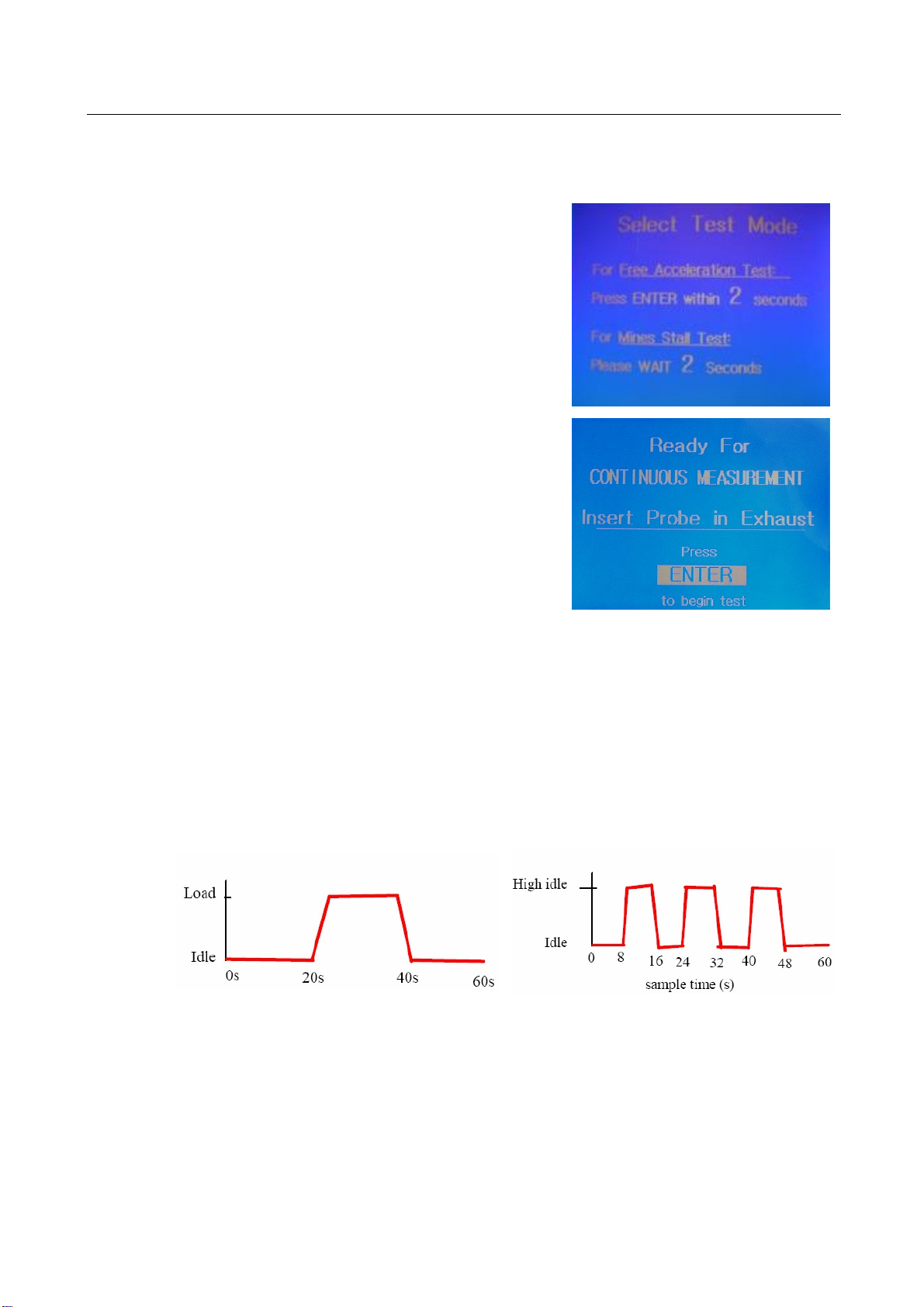
Unlike other DPM measurement methods which require off-line analysis or manual interpreta-
tion, the MPM-4 continuously displays DPM concentration, and provides an immediate overall
test result at completion of a test. This means that maintenance decisions can be made without
delay, and the effectiveness of any maintenance action can be confirmed prior to releasing the
equipment back to the work place.
Weighing less than 9kg (including its integral battery), the instrument is self-contained and is
designed for stand-alone operation. With around 2½ hours testing on a single charge, most
operators prefer to use the instrument on battery power.
Alternatively, the instrument can operate continuously on an external 12V supply. A regulated
12 V DC power pack, which can be connected to a 100-250V, 50/60 Hz AC supply, is supplied
as standard with the instrument. Operating power consumption is typically less than 25 watts.

5
BA314001-en
Designed specifically for operation in the harsh environments typically associated with mobile
and stationary diesel engines, the instrument incorporates a number of features that enhance its
usefulness in "real-world" situations, including:
Simple “one button“ operation
rugged construction for on-site applications
user-maintainable with minimal tools
very wide measurement range (0.1…400 mg/m3elemental carbon)
automatic instrument zero setting prior to every test
field calibration of span easily performed by user.

6
BA314001-en
3 Initial Operation
3.1 Unpacking
The MPM-4M instrument and its accessories are shipped from the factory in a single box. The
box contents are as follows:
MPM-4M instrument
high-temperature sample hose
sample probe
12 volt power supply (100 -- 240 V, 50/60 Hz)
battery charger (100 -- 240 V, 50/60 Hz)
calibration tool
lens cleaning solution
lens cleaning cloth
spare filter elements
operator manual
CD containing “MPM View” second-by-second data capture and graphing software for PC.
3.2 Instrument Setup
Water Trap Sample Filter
Fig. 1: Rear Panel
3.3 Power Supply
The Particle Measurement Unit requires a regulated 12 V DC power source, which may be
either the included power supply (100…250 V, 50/60 Hz) or the pre-installed internal battery.
The power connection is located at the lower left corner of the rear panel. The “connect”
receptacle is used for both the external power pack and the supplied battery charger. The
“Power Source” switch selects either battery or external power operation. The power on/off
switch is at the top left corner of the rear panel.

7
BA314001-en
3.4 Sample In
If not already in place, install the supplied 6mm barbed hose fitting on to the threaded hole in
the black casing of the water trap (the water trap is the clear bowl assembly on the left side of
the rear panel – see Fig. 1 above to view the barbed fitting correctly installed). Connect a
flexible high-temperature hose and sample probe assembly to the barbed fitting.
3.5 Sample Out
If the instrument is used in areas with insufficient air ventilation, connect a 6 mm hose to the
"Sample Out" fitting at the rear of the analyzer to duct exhaust gases away from personnel. Any
water discharged from the water trap also exits from this hose fitting.
3.6 RS 232 Output
The RS 232 interface can be used to integrate the analyzer into the optional MPM-View
software for second-by-second data logging and graphing on a PC (see MPM-View
documentation at the end of this manual). Integration with other MAHA engine and vehicle test
equipment can be achieved using MAHA EUROSYSTEM software. (In most cases it will be
necessary to connect the RS232 cable to the PC or laptop via an RS232-to-USB converter,
which is readily available from most computer suppliers).
Fig. 2: Front Panel
3.7 Analog Output (when installed)
On special order, the MP;-4M can be fitted with dual (low range and high range) analog outputs.
The analog output is available through two standard BNC coaxial connectors on the rear panel
of the instrument.
Figure 3 illustrates the location of these connections.

8
BA314001-en
Fig. 3: Analog Connections on Rear Panel
The output voltages and their values in particle mass concentration (mg/m3) are as follows:
Low Range: 0-25 mg/m31.0mV = 0.01 mg/m3
High Range: 0-800 mg/m31.0mV = 0.2 mg/m3
The voltage versus particle concentration output is linear, as shown on the following charts.
Test data in these charts was generated by recording output voltage corresponding to the
values displayed on the screen (which accounts for some minor deviations due to continuous
minor fluctuations in PM sample concentration).
Fig. 4: Volts vs PM Concentration (mg/m3), Low and High Ranges
3.8 Remote Control (Optional)
If an optionally available wired remote control has been supplied, this may be connected to the
threaded 4-pin connector at the lower right hand corner of the front panel. The connector is
keyed to ensure correct orientation. The function of the remote control is to duplicate the
ENTER key on the front panel, facilitating one-person testing by allowing the instrument to be
operated from the driving position of the vehicle or equipment under test.

9
BA314001-en
4 Operation
4.1 Warm up
To prepare the instrument for testing, connect a
regulated 12V DC supply its connector on the rear
panel and turn on the power to switch. Alternatively the
instrument may be operated from the integral
rechargeable battery.
As well as identifying the instrument and its software
version, it also provides a warm-up count from 600
down to zero seconds (duration 10 minutes) before
automatically switching to normal operating mode with
on-screen display of current concentration.
If desired, the warm-up screen can be exited and the
analyzer put into normal operating mode by simply
pressing the red "Enter" push button switch on the front
panel and holding it down for around two seconds.
During the warm-up process the zero may be slowly drifting. Ensure that the zero is reset
immediately prior to commencement of test measurements.
4.2 Auto-Zero Adjust
After the initial warmup period, the instrument initiates
an auto-zero routine, prompting the operator to ensure
that the sample probe is located in relatively clean air
(for instance, not directly downstream from the exhaust
of an operating engine).
When this has been done, press the red ENTER button
and hold down for at least two seconds. A screen
prompt will tell you when to release the button. In
approximately 5 seconds the auto-zero will be
completed and the screen will change to “test
selection”

10
BA314001-en
4.3 Test Selection
The MPM 4M is pre-programmed to lead the operator
through one of two standardised test procedures;
either a stall test for vehicles and plant with a torque
converter, and a free acceleration test for other types
of equipment, such as vehicles with a manual clutch.
This screen appears automatically after the instrument
has been zeroed. Pressing the ENTER push button
during the 5 second countdown will initiate a free
acceleration test. If the ENTER button is not pushed
during the countdown, the instrument will automatically
initiate a stall test routine.
See the note (next page) for an introduction to the
available tests.
NEW: For continuous measurement, (for instance
while testing for longer periods under actual operating
conditions) hold down the ENTER button while turning
on the power switch. Real-time DPM levels can be
recorded via the MPM-View software on a laptop. This
operating mode also allows calibration checks to be
done more quickly and conveniently.
NOTE
The Appendix to this document contains an extract from the MDG 29 guidelines relating to the
stall and free acceleration tests. The full MDG 29 document covers a wide range of additional
material relevant to management of air quality in underground mines. A hyperlink to the full
MDG 29 document is also in the Appendix.
Each of the pre-programmed tests has a duration of 60 seconds, and both have two engine
modes: for the stall test these are idle and full power; for the free acceleration test they are idle
and full throttle governed engine speed (no load). See (A) and (B) below.
Fig. 3: Stall and Free Acceleration Tests

11
BA314001-en
4.4 Stall Test
Insert Probe
Insert the supplied sample probe fully into the exhaust
of the vehicle or plant under test, using the spring wire
retainers to secure the probe in position. Confirm that
the engine is running and at normal operating
temperature, with the transmission engaged in
accordance with the MDG 29 procedures.
Initiate Test
After inserting the probe, check that the vehicle or plant
under test is chocked or braked to prevent movement
and ensure that all personnel are clear. With the test
operator at the controls, check for clear line of sight to
the MPM-4M screen. When ready, press the ENTER
push button.
The green LED on the front panel will illuminate
(steady) and a 5 second countdown will start, allowing
the operator to anticipate the time when measurements
will commence.
Run Test
Immediately after the countdown, the instrument will
start measuring and storing PM concentration
measurements, and the display will change to the
following “IDLE” screen.
To assist the operator, the green LED will flash slowly,
indicating measuring is ON and the engine should be
at normal idle speed (with the transmission engaged).
After 20 seconds the green LED with start to flash
quickly, indicating the “Full Power” mode of the test. A
this point the operator should rapidly apply full throttle
and hold the engine at full throttle.
The screen changes to show “FULL POWER” and
updates the exhaust PM concentration every second.

12
BA314001-en
After 20 seconds at full throttle the green LED once
again flashes slowly, indicating a return to normal idle
speed. The operator should rapidly return the throttle
to the idle position.
After 20 seconds at idle, measurements are
terminated. At this point the LED is turned off and the
screen flashes a brief “TEST COMPLETED“ message.
The screen then displays the overall test result in bold
characters, together with some other test data which
may aid maintenance personnel to identify any
emission-related faults in the engine or fuel
management system.
To retain the simplicity of the test procedure, manually record the test result, the date/time and
the vehicle or plant identification information.
If it is desired to store the test data directly on a computer connected to the RS232 port on the
MPM-4M, use the supplied “MPM-View” to generate a real-time graph of the PM concentration
profile over the complete test, and record the second-by-second test data in an EXCEL
compatible file. (See the supplied MPM-View operator manual). NOTE: Include the test vehicle
identifier and the date (in YYMMDD format) in the file name when prompted, to facilitate search
and retrieval of stored files.
4.5 Free Acceleration Test
The format of the free acceleration test is similar to that of the Stall Test, but there are some
important differences, notably:
testing is performed with the transmission in neutral.
there are three acceleration peaks, compared with just one in the Stall Test.
For completeness, the full test procedure follows.
Insert Probe
Insert the supplied sample probe fully into the exhaust
of the vehicle or plant under test, using the spring wire
retainers to secure the probe in position. Confirm that
the engine is running and at normal operating
temperature, with the transmission disengaged in
accordance with the MDG 29 procedures.

13
BA314001-en
Initiate Test
After inserting the probe, check that the vehicle or plant
under test is chocked or braked to prevent movement
and ensure that all personnel are clear. With the test
operator at the controls, check for clear line of sight to
the MPM-4M screen. When ready, press the ENTER
push button.
The green LED on the front panel will illuminate
(steady) and a 5 second countdown will start, allowing
the operator to anticipate the time when measurements
will commence.
Run Test
Immediately after the countdown, the instrument will
start measuring and storing PM concentration
measurements, and the display will change to the
following “IDLE” screen.
To assist the operator, the green LED will flash slowly
for 8 seconds, indicating measuring is ON and the
engine should be at normal idle speed (with the
transmission engaged).
The green LED will then flash quickly for a further 8
seconds, indicating the first “Full Throttle” (Regulated
Speed) mode of the test. A this point the operator
should rapidly apply full throttle and hold the engine at
full throttle. The screen changes to show “FULL
POWER” and updates the exhaust PM concentration
every second.
Subsequently, every 8 seconds the LED flashing
speed and screen display alternate between Idle and
Full Power Modes.

14
BA314001-en
Full Power
Idle
Full Power
Idle (12 seconds)

15
BA314001-en
After the final 12 seconds at Idle, measurements are
terminated. At this point the LED is turned off and the
screen flashes a brief “TEST COMPLETED“ message.
The screen then displays the overall test result in bold
characters, together with some other test data which
may aid maintenance personnel to identify any
emission-related faults in the engine or fuel
management system.
4.6 Continuous Measurement
The MPM-4M also has a capability to continuously measure and record DPM concentration.
This feature is very useful if you wish to record DPM over an extended period, such as on-
vehicle monitoring during normal work activities. NOTE: to log data in the continuous measuring
mode, the MPM-4M must be connected to a PC (laptop) with the MAHA Emission Viewer
software running (see separate user manual).
To initiate the continuous measuring mode, turn the MPM-4M OFF, then, while holding down
the ENTER button, switch the MPM-4M back ON. The screen will then prompt you to release
the ENTER button.
After setting the probe in the tailpipe of the equipment under test, press ENTER once again and
continuous measurement will commence, after a 5 second countdown.
NOTE: Include the test vehicle identifier and the date (in YYMMDD format) in the file name
when prompted, to facilitate search and retrieval of stored files.
Running vehicle engines in closed areas represents a risk of potential carbon
monoxide poisoning.
The operator/owner is responsible for providing sufficient air ventilation.

16
BA314001-en
5 Calibration
The analyzer has been factory calibrated to deliver a linear output directly proportional to the
concentration of PM. Given the linearity of response, a simple "Zero and Span" check provides
an excellent and rapid confirmation of calibration status. The supplied calibration generates the
span response. The procedure follows:
1 Perform the "Warm up" and "Zero Adjust" procedures above.
2 Put the instrument in "Continuous Measuring" mode (see above), with the sample probe
resting in relatively clean air (i.e., not downstream of any vehicle exhaust).
3 Remove the operating plug from the rear panel of the analyser by rotating it counter-
clockwise and then pulling directly from its socket. If the plug has not been removed for
some time, it may require a firm pull to overcome O-ring friction. Occasional light application
of O-ring grease will help to avoid this.
Fig. 4: Calibration Plug (left) and Operating
Plug (right)
4 After carefully cleaning the calibration plug using a lint-free cloth (DO NOT use paper
tissue), insert the calibration plug and rotate clockwise until it is firmly engaged on the stop
pins. Ensure that the plug is oriented so that painted dot on the back face of the calibration
plug is aligned with the dot on the instrument case.
Fig. 5: Back Face of Calibration Plug
5 Confirm that the reading on the screen is approximately the same as the label on the
calibration plug (±10%).

17
BA314001-en
6 If it is determined that the span value has drifted, remove the top panel of the instrument
case. Carefully remove the Detector Head and clean the lens, using the same general
procedures as for the calibration plug. When replacing the detector head, ensure that the
painted dot on the detector flange is oriented to be adjacent to the dot on the measuring
chamber.
Fig. 6: Location and Correct Installation of
Detector Head on the measuring chamber
7 After proceeding as above, if the display reading is still not within the figure marked on the
calibration plug, unscrew and remove the lid of the PCB’s protective box (silver aluminium)
and adjust the arrowed multi-turn potentiometer using a fine screwdriver until the values
closely match.
Fig. 7: Potentiometer Adjustment
8 When completed, replace the PCB box lid, remove the calibration plug and replace it with the
operating plug. Place the calibration plug in the supplied black plastic protective sleeve.
Store in a secure place.

18
BA314001-en
6 Maintenance
Apart from routine zeroing and occasional range calibration, the instrument requires very little
maintenance. The only consumable items are the high-efficiency HEPA filters (internal and
external) used, respectively, to clean the airflow protecting the optical system lenses and to
remove particles from the sample stream before discharging to atmosphere.
6.1 Checking and Replacing the Rear Panel Filter
A high performance HEPA filter, manufactured to remove >99.9% of all particles down to
0.1micron size, is installed on the rear panel of the instrument.
Fig. 8: Rear Panel Filter
The filter cartridge should be examined for evidence of particle "breakthrough" on the surface of
the filter media (the white cylinder inside the clear casing).
The filter should be checked daily. Filtered sample flows from the inside to the outside of the
media. If black or dark brown discolouring is evident on the media surface, the element must be
replaced. The filter in the above picture has gone a long way past the point when it should have
been replaced!
To replace the media element, first unscrew and remove the clear plastic filter bowl. Then
unscrew and remove the black plastic media retainer, together with the media element. Remove
and replace the element with one of similar specification.
Replacement and reassembly are the opposite sequence to above. When installing the clear
plastic filter bowl, do not over-tighten the threads, as this may make subsequent removal
difficult. Sealing is effected by the O-ring on the cylindrical body, not by end contact, so do not
rotate the bowl further once resistance is felt. Occasionally lightly smear the O-ring with an
appropriate lubricant.

19
BA314001-en
6.2 Checking and Replacing the Internal Filter
The same visual check applies to the internal “shield air” filter cartridge, but this filter is
disposable and replaced as a single unit.
Remove the eight case cover retaining screws and lift off the cover. Remove the filter cartridge
from its spring clip, gently detached from the hose and replaced by a similar specification filter.
It is recommended that this check is done monthly. The following photograph shows the correct
orientation for re-fitting the disposable filter.
Fig. 9: Internal Filter Orientation
7 Disposal
If you want to dispose of the equipment, please contact your MAHA dealer or the following
address, indicating equipment type, date of purchase and serial number:
MAHA Maschinenbau Haldenwang GmbH & Co. KG
Hoyen 20
87490 Haldenwang
Germany
Phone: +49 (0) 8374 585 0
Fax: +49 (0) 8374 585 500
Alternatively, you may take the equipment to a specialised waste management plant to ensure
that all components and operating liquids are properly disposed of.

20
BA314001-en
8 Annex
MDG 29 Test Procedures (Extract)
The following text is an extract from the MDG 29 document (full title “Guideline for the
management of diesel engine pollutants in underground environments”). The complete
document can be downloaded from:
http://www.dpi.nsw.gov.au/__data/assets/pdf_file/0018/225513/MDG-29-Guideline-for-the-
management-of-diesel-engine-pollutants-in-underground-environments.pdf
6.3.2 Procedures for Monitoring Raw Diesel Particulate Emissions
6.3.2.1 Standard Method
All diesel particulate testing shall be carried out using the following method unless the diesel
engine cannot be held in the load condition for 20 seconds in which case testing shall be carried
out in accordance with clause 6.3.2.2 below.
a Testing equipment shall comply with clause 8.2 Diesel Particulate Monitoring Equipment.
Note:
It is not possible to use the Bosch Smoke Meter for the above tests due to its inability to
measure over a 60 second sampling period.
b Exhaust sampling and analysis shall be carried out by a person competent to the satisfaction
of the mine mechanical engineer to carry out such test or by a licensed laboratory.
c The diesel engine shall be operated until the engine temperature stabilises. Exhaust
particulate sampling and analysis shall be performed when the diesel engine is at normal
operating temperature.
d The vehicle must be safely chocked and the vehicle brakes must be applied.
Important Safety Notice:
As engines must be tested in the load condition requiring the drive train to be engaged during
testing it is important the vehicle is adequately chocked or restrained and the brakes applied to
ensure it cannot “jump” or run away while the diesel engine is under throttle during the test.
e Place vehicle in third gear or other gear as specified by the equipment manufacturer to carry
out the test.
f Run the engine at idle speed.
g Insert sensor probe into the undiluted raw exhaust before any particulate treatment.
Note:
This may be downstream of catalytic converters and water based scrubbers but must be before
any particulate filter.
h Testing shall be carried out over a 60 second cycle and on the undiluted raw exhaust as
indicated in Figure 1 below.
Notes:
1 It is important that the timing of the idle and full throttle settings is as accurate as possible.
To ensure good repeatability, it is advisable for the operator to practice the procedure
several times prior to collecting a sample.
2 Sampling should commence in the first idle period and continue until the final idle period.
3 Engines with a constant load, such as a diesel generator or pump should be analysed with
the load applied over the full 60 seconds.
I Start sampling timer on analyser.
j After 20 seconds have an operator quickly apply full throttle to engine (still in third gear) and
hold for 20 seconds.
k Quickly release throttle and allow engine to decay to idle while sampling for 20 seconds.
Table of contents