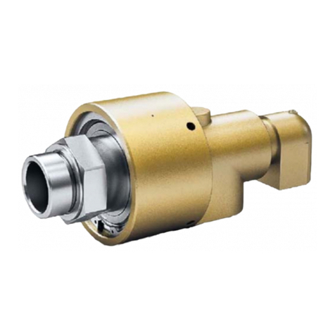
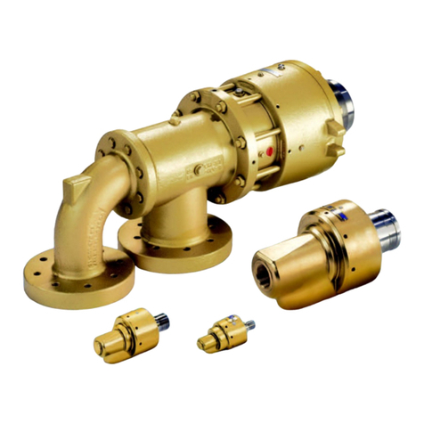
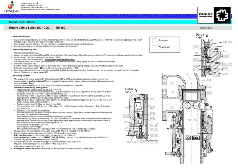
Maier novasys DP Series User manual

Operating Instructions Maier Rotary Joints
Series DP B-DP_en - Version 7– 16.02.2011
Christian Maier GmbH & Co. KG Maschinenfabrik
Würzburger Str. 67-69 Postfach 16 09
D-89520 Heidenheim D-89506 Heidenheim
+49 7321 317-0; +49 7321 317-139; vkd@ maier-heidenheim.de; www.maier-heidenheim.de

Operating Instructions Maier Rotary Joints
Series DP B-DP_en -Version 4 – 14.02.2011
Keep these instructions for future reference! 1
Contents
1Safety ..............................................................................................................................................................................2
2Design and function .........................................................................................................................................................3
3Information on design and mounting................................................................................................................................4
4Transport und Lagerung ..................................................................................................................................................4
5Mounting..........................................................................................................................................................................5
6Operation.........................................................................................................................................................................7
7Maintenance ....................................................................................................................................................................8
Christian Maier GmbH & Co. KG reserves the copyright to this manual. The instructions, information and illus-
trations contained in this manual may not be copied in any way, neither partially nor completely. Neither may the
instructions, information and illustrations be disclosed to third parties nor used to create competing products,
systems or facilities or assist in such activities in any way.

Operating Instructions Maier Rotary Joints
Series DP B-DP_en -Version 4 – 14.02.2011
Keep these instructions for future reference! 2
1. Safety
Application
Maier rotary joints may only be used as fittings to connect pressurized pipes carrying liquids to rotating
pressure systems. Such rotating pressure systems are, for example, rollers through which flow liquids for
cooling or heating purposes. Series DP rotary joints are primarily used for water. Series DP … - 800 is
available for usage with thermal oil. Other media are possible - please contact the manufacturer for de-
tails. Please refer to the section "Specifications and Spare Parts" for details on approved media and
their qualities/properties. These values are binding for the application.
Never modify the rotary joint or tamper with it in any way as this may cause dangers. Install, operate and
maintain the rotary joint only as described in these operating instructions. We shall not be liable for any
damages or plant interruptions whatsoever resulting from failure to observe these operating instructions.
These operating instructions do not contain all information important for the safe operation of the rotary
joint. Also observe all pertinent local and national regulations and legislation concerning workplace safety
and prevention of accidents.
Use only genuine or Maier-approved spare parts (standard norm parts). If you use other parts, this may
have adverse effects on the safety of the rotary joint.
1.1 Requirements concerning installation and maintenance staff as well as operators
Only staff that has read and fully understood these operating instructions and that is fully aware of the dan-
gers resulting from the rotary joint as well as the appropriate safety measures may work with Maier rotary
joints. Such staff must have at least the knowledge of a trained locksmith or industrial mechanic who has
experience with pressurized components.
1.2 Dangers
Warning!
If you touch hot parts or come into contact with hot liquids escaping under high
pressure, this may result in dangerous burns.
Mount a protective hood to the rotary joint in order to prevent persons from di-
rectly coming into contact with hot parts and to safely retain escaping medium.
Warning!
If the rotary joint blocks and rotates along with the roller, the hoses may be torn off
so that hot liquids can escape under high pressure.
Always observe the design and mounting information in chapter 3.
Monitor the rotary joint by means of a torque sensor or a vibration pickup.
Ensure that the rotary joint is regularly maintained as per chapter 7
1.3 Safety precautions
Always observe the following safety precautions for the operation of the rotary joint:
DP rotary joints that are operated at temperatures of more than 80°C (176°F) must be relubricated (see
7.2 on page 8).

Operating Instructions Maier Rotary Joints
Series DP B-DP_en -Version 4 – 14.02.2011
Keep these instructions for future reference! 3
2 Design and function
2.1 Function and components
Maier rotary joints are fittings used to connect pressurized pipes to rotating
pressure systems. Such rotating pressure systems are, for example, rollers
through which flow liquids, gases or steam for cooling or heating purposes.
Housing connections:
The connection to the stationary pressurized system is made by the station-
ary part of the rotary joint – the housing or the angle piece. Different rotary
joint versions are available:
Mono version: housing with one connection for supplying or removing the
medium to or from the rotating pressure system (version 1). DP rotary joints
are always delivered as mono version. Angle pieces must be used for
duo versions.
Duo version: rotary joint DP and angle piece for supplying and removing the
medium to and from the rotating pressure system. The second channel is
formed by an inner pipe that is centered in the center axis of the rotating
part.
The design of the inner pipe differs in terms of the following versions:
Stationary inner pipe (version 2): The inner pipe is screwed into the an-
gle piece (standard version always with right-hand thread).
Rotating inner pipe supported in angle piece
(version PR 2): The inner pipe is supported by the stationary angle
piece. There is wear at the bearing point.
Stationary inner pipe with floating bearing in O ring and anti-rotation
lock by means of screw (version PO 2): The inner pipe is held in the
angle piece by means of an O ring. A screw prevents it from rotating.
There is wear at the bearing point.
This also applies to series -800 with the difference, however, that the duo
version has an additional Viton O ring between angle piece and housing for
sealing purposes.
Rotor connections:
The connection to the rotating pressurized system is made by the rotating
part of the rotary joint – the rotor. The rotor is mounted to the rotating pres-
sure system (e.g. a roller) by means of a right-hand or left-hand thread R / L,
flange K (DN 40 (1½″) and 50 (2″)) or a fixed flange F (DN 40 (1½″) and
50 (2″)). The system is sealed by means of a sealing cone, flat packing or
an O ring.
Please refer to our catalog and the corresponding outline drawing for further
information.

Operating Instructions Maier Rotary Joints
Series DP B-DP_en -Version 4 – 14.02.2011
Keep these instructions for future reference! 4
3 Information on design and mounting
Attention!
Damage to components due to vibration and heat expansion.
Use only flexible hoses to connect the rotary joint!
Use flexible metal hoses for the connection between the supply pipe system and the rotary joint hous-
ing. This compensates for heat expansion and vibrations.
Never apply torsional, tensile or pressure forces to metal hoses. Observe the minimum bending radii
quoted by the hose manufacturers. Never use axial compensators.
Use flat packings made of pure graphite to securely seal flange connections.
Only operate rotary joints sizes DN 65 … 100 with a sufficiently dimensioned torque support. The sup-
port element must allow for axial and radial movements of the housing. For sizes DN 06 … 50, due to
low friction torque support by the hoses is sufficient.
For DN 65 and greater install an additional safety unit:
Install a torque monitoring system or a bearing monitoring system with vibration pickup (e.g. FAG or
SKF) with connection to the emergency shutdown system in order to avoid bearing damages and con-
sequential damages.
If the monitoring system is activated, the rotation of the roller should be stopped immediately and the
supply of the medium should be interrupted upstream of the metal hoses.
Center the inner pipe and the roller as well as the rotary joint. Run-out and axial tension will lead to mal-
functions of the rotary joint.
For smooth operation of rotary joint ensure concentricity and minimum run-out tolerance at roller or in-
termediate flange.
In the case of a rotary joint with rotating inner pipe it is recommended to use a stainless steel inner pipe
or at least a hard chromium-plated bearing seat.
Operation at water temperatures exceeding 70°C (158°F):
In order to ensure maximum reliability and service life of the seals in the rotary joint, the hot water used
in the rotary joint must be processed, treated and conditioned according to the DdTÜV Guidelines Tech-
nical Chemistry 1466 (VdTÜV - Merkblatt Technische Chemie 1466). The circulated water must have a
low salt concentration and a maximum conductivity of < 100 S/cm (100µmho/cm)!
If the salt concentration is high, this may result in deposits in the seal gap and premature failure of the
seal!
4 Transportation and storage
The rotary joints may only be stored in the original package.
Make sure the storage conditions specified in the "Specifications and Spare Parts" are met.
If the rotary joint itself or the facility in which the rotary joint is installed is to be preserved, make sure the
preservation agent and the seals of the rotary joint are compatible.

Operating Instructions Maier Rotary Joints
Series DP B-DP_en -Version 4 – 14.02.2011
Keep these instructions for future reference! 5
5 Mounting
5.1 Mounting the rotary joint to the roller
Mount rotary joint 1 to roller W:
as per drawing A with thread at rotor
as per drawing B with K flange 2 and inner ring 3
as per drawing C with fixed flange 4.
Seal with a sealing cone (rotor R/L), O ring 6, flat packing 7
or another suitable sealing element.
Fasten the rotary joint with screw 8 or stud bolt 9 and nut 10.
Clean sealing surfaces DF.
Place the sealing element into roller W (drawing B).
Recommended material for flat packing:
pure graphite with metal insert.
Duo version rotary joint:
version P 2: screw inner pipe J into angle piece
version PR 2: insert inner pipe J into the angle piece, center
the pipe, no tension allowed.
version PO 2: screw inner pipe J with O ring and anti-rotation
unit into angle piece (inner pipe available for type PO2).
Mount K flange 2 with screws over rotor 80 and place inner
ring 3 into rotor groove. Mount stud bolts 9 (drawing B).
Lift the rotary joint and insert it into the centering unit of the
roller.
Versions with inner pipe: the inner pipe must be centered
with reference to the rotary joint and the roller. If you en-
counter resistance, check for correct position. Run-out and
axial tension cause malfunctions of the rotary joint.
Mount screws 8, 11 and nuts 10. Maximum admissible tor-
que as per "Specifications and Spare parts".
Attention:
When sealing with flat packing, do not fully tighten the
screws until you have aligned the rotary joint as per sec-
tion 5.2!
Assure the minimum distance MA is at least 1mm - oth-
erwise leakage will occur at the sealing element and the
rotary joint and the inner pipe will be damaged:
drawing B : MA ≥1 mm (0.04”)
drawing C : MA1 = 0 mm (0.00”)
MA2 ≥1 mm (0.04”)
Note!
For smooth operation of rotary
joint ensure concentricity and minimum
run-out tolerance of roller
Fig 7. Mounting the rotary joint to the
roller

Operating Instructions Maier Rotary Joints
Series DP B-DP_en -Version 4 – 14.02.2011
Keep these instructions for future reference! 6
5.2 Aligning the rotary joint, sealing with flat packing
Place dial gauge M from the idle machine frame MG
onto the rotary joint.
Rotate roller W until the dial gauge is at the bottom
dead center UT. Mark the pointer position.
Rotate roller until you reach the upper dead center
OT.
Tighten the bottom screws Su until the dial gauge is
in the center position.
Repeat this alignment process until you reach the
concentricity tolerance specified in the table.
Tighten the screws with the admissible torque as per
"Specifications and Spare Parts"!
Fig 8. Aligning the rotary joint
Admissible concentricity tolerance
n (min-1 / rpm)
DN [mm] DN [inch] 100 400 > 400
03-50 1/8- 2 0,25mm (±0.01″)
65 - 100 2½ - 4 ± 0,1mm (±0.004″)
5.3 Connecting the rotary joint
Attention!
The rotary joints must never run dry since this may damage them. Exception: test
run for a maximum of 30 minutes a very low speeds.
Mount torque monitor or vibration pickup.
Connect the housing.
Route the hoses as shown in fig. 4.
Do not route the hoses as shown in fig. 5.
.
Note!
Observe the information in section 3!
Fig 9. Connecting the rotary joint

Operating Instructions Maier Rotary Joints
Series DP B-DP_en -Version 4 – 14.02.2011
Keep these instructions for future reference! 7
6 Operation
Attention!
Danger of damage to the rotary joint if is not operated as per instructions.
Never operate the rotary joint beyond the application data limits specified in
"Specifications and Spare Parts"!
Observe the limitations specified in section 0 on page 2!
6.1 Observe and check during operation
Check the following during operation:
Check for centric arrangement of the rotor with reference to the roller cog. The radial deflection at the
rear area of the housing must not exceed the values in chapter 5.2 (Admissible concentricity tolerance).
Place a dial gauge from the idle machine frame onto the rotary joint housing to check.
Check the quality of the medium in the system and record the values.
Check for visible leaks at the relief connection of the rotary joint. The operating behavior of the rotating
mechanical seal installed does not change suddenly. If the seal is beginning to fail, this is indicated by
slowly increasing leakage. Regular checks allow you to acquire values concerning the operating behav-
ior of the rotary joint installed in the system.
6.2 Troubleshooting
Problem Reason Repair
Leakage at the hous-
ing via the relief holes
Rotating mechanical seal is
damaged or worn.
Install a new rotating mechanical seal. Check the quality of
the medium and the bearings.

Operating Instructions Maier Rotary Joints
Series DP B-DP_en -Version 4 – 14.02.2011
Keep these instructions for future reference! 8
7 Maintenance
7.1 Safety during maintenance
Only staff that has read and fully understood these operating instructions and that is fully aware of the dan-
gers resulting from the rotary joint as well as the appropriate safety precautions may work with Maier rotary
joints. Such staff must have at least the knowledge of a trained locksmith or industrial mechanic who has
experience with pressurized components.
Perform work on the rotary joint only when the machine/system is idle.
Allow the rotary joint to cool down before you take up work or wear safety equipment to protect against the
heat.
Always wear safety glasses when performing work on the rotary joint to protect against escaping medium.
Use only genuine Maier or Maier-approved spare parts (standard norm parts). If you use other parts, this
may have adverse effects on the safety of the rotary joint.
Maier offers on site specialist service. We can also train your service staff - just get in touch with us!
If you have to remove protective equipment to perform the work, refit such equipment when you are done
and check it for proper operation.
Make sure to properly tighten all screws (see sheet "Specifications and Dimensions").
Always observe the safety information in chapter 1 on page 2.
7.2 Maintenance plan
Due to lifetime lubrication, the rotary joints are maintenance-free up to operating temperatures of up to
max. 80°C (176°F). The bearings must be lubricated if the rotary joints are operated at greater tempera-
tures. Please refer to "Specifications and Spare Parts" for information on lubrication intervals and volumes.
Interval Activity Explanation
According to section
"Specifications and
Spare Parts“
Lubricate DP rotary joints depending
on operating temperature.
Lubrication volume depends on the nominal di-
ameter of the rotary joint (see section "Specifi-
cations and Spare Parts“).
Every 12 months Check all bearings and seals and
replace them
By Maier customer service

Specifications and Spare Parts
Series DP S-DP_en -Version 7 – 16.02.2011
Keep these instructions for future reference! S1
Contents
Table 1: Application data ................................................................................................................................................................1
Table 2: Transportation and storage ...............................................................................................................................................1
Table 3: Bearing lubrication ............................................................................................................................................................2
Table 4: Tightening Torques for Fastening Screws.........................................................................................................................2
Approved media for the pressure pipe ............................................................................................................................................3
Specifications - standard media......................................................................................................................................................3
DP DN 10 – 50 (3/8 ″- 2″)...............................................................................................................................................................5
P N 10 … 50 (3/8’’ … 2’’) .................................................................................................................................................................6
DP … -800 DN 10 … 50 (3/8’’ … 2’’)..............................................................................................................................................7
P …- 800 DN 10 – 50 (3/8’’ … 2’’)....................................................................................................................................................8
At DN 15 and 20: Elbow with additional adapter! ............................................................................................................................8
Inner pipe for Elbow PO 2 …- 800 ..................................................................................................................................................8
DP Spare parts DN 10 – 50 (3/8’’ … 2’’) ..........................................................................................................................................9
DP DN 06 and Spare Parts...........................................................................................................................................................10
DP1 DN 65 – 100 (2½″- 4″) ........................................................................................................................................................11
DP2 DN 65 – 100 (2½″- 4″) ........................................................................................................................................................12
DPR2 DN 65 – 100 (2½″- 4″)......................................................................................................................................................13
Spare Parts for types DP1, 1, R2, - DN 65 – 100 (2½″-4″) .........................................................................................................14
DPN1 D 10 – 50 (3/8″- 2″)............................................................................................................................................................15
DPN2, DPNR2 DN 10 – 50 (3/8″- 2″) ...........................................................................................................................................16
Spare Parts for types DPN1, 2, R2, - DN 10 – 50 (3/8″- 2″).........................................................................................................17
Journal Flanges for K Rotor Connection .......................................................................................................................................18
Table 1: Application data
Series DP DP DP-800 DP DPN
Type 1, 2, R2 1B, 1C, 2,
R2
Nominal diameter DN
Nominal diameter DN
[mm]
[inch]
…06
… 4
1
10 … 50
8
3… 2
10 … 50
8
3… 2
65 … 100
22
1… 4
10 … 50
8
3… 2
Medium
Compres-
sed air,
water
Hydraulic
Oil Water Thermal
Oil Water Water
Temperature max. °C
max. °F
… 120
… 248
… 80
… 176
-10 … 160
14 … 320
… 160
… 320
-10 … 140
14 … 284
-10 … 90
14 … 194
Pressure PN, min.…max. bar
min… max. psi
… 10
… 145
… 80
1160
-0,2 … 10
-2.9 …145
… 10
… 145
-0,2 … 10
-2.9 ...145
-0,2 … 10
-2.9 … 10
Speed max. min-1
max. rpm 55000
DN [mm]
55000
DN [mm]
55000
DN [mm]
55000
DN [mm]
55000
DN [mm]
Speed limite
for formula values
max. min-1
max. rpm 3000 400 2500 2500 850 2500
Avoid operating the unit under conditions involving several maximum values attained at the same time! Inquire for
greater values and other media.
Table 2: Transportation and storage
Storage temperature 15 °C to 30 °C
59 °F to 86 °F
Humidity 65 %
Preservation none; check compatibility with seal materials, if neces-
sary

Specifications and Spare Parts
Series DP S-DP_en -Version 7 – 16.02.2011
Keep these instructions for future reference! S2
Table 3: Bearing lubrication
Lubricant Lubrication at grease nipple – used grease escapes at the housing.
You may use any other grease that meets the application and operation conditions.
The rotary joints are factory-lubricated with PETAMO GY 193, Klüber Lubrication KG (phone.:
++49-(0)89-7876-271 | www.klueber.com)
DN mm
DN inch
…06
…¼
10
3/8
15
½
20
¾
25
1
32
1¼
40
1½
50
2
65
2½
75
3
80
3½
100
4
Q grease * -*1 3 4 5 6 8 10 15 20 35 35 50
Volume
* strokes of a grease gun according to DIN 1283 with 1.2 cm3(0.073in³) / stroke
up to 80°C
up to 176°F
80°C to 120°C
176°F to 248°F
120°C to 140°C
248°F to 284°F
140°C to 160°C
284°F to 320°F
Interval
*1 factory lifetime lubrica-
tion
every 6 months every 12 weeks every 2 weeks
Table 4: Tightening Torques for Fastening Screws in Nm (ft lbf) with friction in the thread and connecting surface
with µ = 0,14 and …
Property class 5.6 at a screw temperature of
Size 20°C
68°F
100°C
212°F
150°C
302°F
200°C
392°F
250°C
482°F
300°C
572°F
M 6 4,0
(2.95)
3,6
(2.66)
3,4
(2.51)
3,1
(2.29)
2,9
(2.14)
2,7
(1.99)
M 8 10,0
(7.38)
9,0
(6.64)
8,5
(6.27)
7,9
(5.83)
7,3
(5.38)
6,6
(4.87)
M 10 18
(13.28)
16
(11.80)
15
(11.06)
14
(10.33)
13
(9.59)
12
(8.85)
M 12 37
(27.29)
33
(24.34)
31
(22.86)
29
(21.39)
26
(19.18)
24
(17.70)
M 16 90
(66.38)
81
(59.74)
76
(56.05)
71
(52.37)
65
(47.94)
60
(44.25)
M 20 175
(129.07)
158
(116.53)
148
(109.16)
138
(101.78)
127
(93.67)
116
(85.56)
Property class 8.8 at a screw temperature of
Size 20°C
68°F
100°C
212°F
150°C
302°F
200°C
392°F
250°C
482°F
300°C
572°F
M 6 10,0
(7.38)
9,3
(6.86)
8,9
(6.56)
8,4
(6.20)
8,0
(5.90)
7,5
(5.53)
M 8 24,0
(17.70)
22,3
(16.45)
21,3
(15.71)
20,3
(14.97)
19,1
(14.09)
18,0
(13.28)
M 10 48
(35.40)
45
(33.19)
43
(31.72)
41
(30.24)
38
(28.03)
36
(26.55)
M 12 82
(60.48)
76
(56.05)
73
(53.84)
69
(50.89)
65
(47.94)
62
(45.73)
M 16 206
(151.94)
192
(141.61)
183
(134.97)
174
(128.34)
164
(120.96)
155
(114.32)
M 20 400
(295.02)
372
(274.37)
355
(261.83)
338
(249.30)
319
(235.28)
300
(221.27)
The property class is indicated by the designation of the fastening element. Please inquire for data on other materials

Specifications and Spare Parts
Series DP S-DP_en -Version 7 – 16.02.2011
Keep these instructions for future reference! S3
Approved media for the pressure pipe
Series DP … 06 may be used for water,compressed air and hydraulic oil, the series DP and DPN for water, having the quality
described below. Other media including additives (e.g. anticorrosion or antifreeze agents) must be checked for compatibility with
the sealing materials at the manufacturer's site.
Thermal oil must not be used under any circumstances since the elastomers used in the units are not compatible with such me-
dia! Use only type DP … -800 rotary joints for thermal oil!
Specifications - standard media
General
The quality of the water used plays a decisive role regarding the service life and reliability of Maier rotary joints. It is strongly rec-
ommended that the media the specifications listed below. Inappropriate water quality will result in heavy wear of the seals and
premature failure of the rotary joint.
Section 1: Water at temperatures -10°C - 70°C (14°F – 158°F) for rotary joint DP and DPN
General: clear, no sediments
Filtration: particle size 20 µm (788µin), max. 50µm (1969µin]
Water hardness: < 3,2 mmol/l (322 ppm CaCO3)
If required, add a suitable antifreeze agent and a silicate-free anticorrosion agent (ensure compatibility with the materials
used in the unit, check back with manufacturer, if necessary).
Section 2: Water at temperatures > 70°C (158°F) for rotary joint DP and DPN
General: clear, no sediments
Filtration: particle size 20 µm (788µin), max. 50µm (1969µin]
Water hardness: < 3,2 mmol/l (322 ppm CaCO3)
Low salt concentration according to VdTÜV- Guideline TCh 1466 "Guideline for Circulation Water in Hot Water and Warm
Water Heating Systems" ("Richtlinie für das Kreislaufwasser in Heißwasser – und Warmwasserheizungsanlagen), sheet 1
If required, add a suitable antifreeze agent and a silicate-free anticorrosion agent (ensure compatibility with the materials
used in the unit, check back with manufacturer, if necessary).
Section 3: Thermal oil temperature < 160 °C (320°F) for rotary joint series DP … -800
Material groups: 1. Thermal oil consisting of hydrocarbons (mineral base, group 1)
2. Thermal oil made of isomer mixture (synthetic base – group 2)
Only upon request:
Thermal oil consisting of uniform material (synthetic base – group 3)
General: clear, no sediments
Filtration: particle size 50 µm,(1969µin) max. 100µm (3937µin)
Steam pressure*: The steam pressure must not exceed 0.5 bar (7,25 psi) abs at maximum operating tempera-
ture.
*: Steam pressure is the pressure at which a liquid becomes gaseous. The steam pressure depends on the temperature of
the liquid.
Specific heat
conductivity:
For maximum heat dissipation in the sealing gap, the value should be as good as possible.
Kinematic
viscosity:
For excellent flow in the system and lubrication effect in the rotary joint, the following values
should be attained:
- as low as possible at minimum application temperature
- as high as possible at maximum application temperature.

Specifications and Spare Parts
Series DP S-DP_en -Version 7 – 16.02.2011
Keep these instructions for future reference! S4
Section 4: Hydraulic oil with temperature up to max. 80 °C (176 °F) for rotary joint series DP …06
We recommend to use Hydraulic oil acc.to DIN 51524 or better with the purity class 21/19/16 acc. to ISO 4406/99 It
should be noted, that transport and storage has a strong influence on the oil purity. Any way, you must accurately filter the fluid
when filling, to ensure the oil purity required.
Particle size 4µm Particle size 6µm Particle size 14µm
ISO Code Particle quantity / 100ml ISO Code Particle quantity / 100ml ISO Code Particle quantity / 100ml
from to from to from to
21 1.000.000 2.000.000 19 260.000 500.000 16 32.000 64.000
Section 5: Compressed air with temperature up to max. 120 °C (248 °F) for rotary joint DP … 6
Air food grade (dry and oil-free)
Compressed air quality acc.to DIN ISO 8573-1
Particle quantity /m³
Particle size d (µm) Pressure dew point Residual oil content
0,1 < d <=0,5 0,5 < d <=1 1 <d <=5 °C °F (mg/m³)
100.000 1.000 10 <= +3 <= + 37.4 0,01

Specifications and Spare Parts
Series DP S-DP_en -Version 7 – 16.02.2011
Keep these instructions for future reference! S5
DP DN 10 – 50 (3/8 ″- 2″)
DN [mm] 10 15 20 25 32 40 50
DN[inch] 3/81/23/41 11/411/22
Type DP 10 R 51 DP 15 R 51 DP 20 R 51 DP 25 R 51 DP 32 R 51 DP 40 R 51 DP 50 R 51
Order-No. 1112050-051 1112100-051 1112150-051 1112200-051 1112250-051 1112300-051 1112350-051
Type DP 10 L 51 DP 15 L 51 DP 20 L 51 DP 25 L 51 DP 32 L 51 DP 40 L 51 DP 50 L 51
Order-No. 1112051-051 1112101-051 1112151-051 1112201-051 1112251-051 1112301-051 1112351-051
Type DP 40 K 91 DP 50 K 91
Order-No. 1112302-091 1112352-091
Type DP 40 F 91 DP 50 F 91
B2 =G
Order-No. 1112303-091 1112353-091
Type DP 10 R 11 DP 15 R 11 DP 20 R 11 DP 25 R 11 DP 32 R 11 DP 40 R 11 DP 50 R 11
Order-No. 1112050-011 1112100-011 1112150-011 1112200-011 1112250-011 1112300-011 1112350-011
Type DP 10 L 11 DP 15 L 11 DP 20 L 11 DP 25 L 11 DP 32 L 11 DP 40 L 11 DP 50 L 11
Order-No. 1112051-011 1112101-011 1112151-011 1112201-011 1112251-011 1112301-011 1112351-011
Type DP 40 K 01 DP 50 K 01
Order-No. 1112302-001 1112352-001
Type DP 40 F 01 DP 50 F 01
Housing connection
B1=NPT
Order-No. 1112303-001 1112353-001
Ø A 9,5 13 17,5 22 30 35 47
B1 G 3/8 G 1/2 G 3/4 G 1 G 11/4 G 11/2 G 2
B2 3/8″NPT 1/2″NPT 3/4″NPT 1″NPT 11/4″NPT 11/2″NPT 2″NPT
D G 3/8 A G 1/2 A G 3/4 A G 1 A G 11/4 A G 11/2 A G 2 A
F1 88 98 112 128 153 176 191
F2 164 201
F3 170 192
Ø J 54 58 74 84 100 110 137
Ø K2 G7/h8 50 65
Ø K3 H7/f7 65 80
M 24 25 31 36 42 45 57
O2 10 10
O3 20 20
PG ±5 26,5 24 30 37 46 53,5 60
U 15 18 17 20 26 27 27
Ø AD 100 125
AZ x Ø DB 5x9 5x11
JG 1/4″NPT 3/8″NPT 1/2″NPT 3/4″NPT 1″NPT 11/4″NPT 11/2″NPT
KB 15 15
Ø LK 80 100
SW 24 30 36 46 55 60 75
weight kg 0,8 1 1,8 2,4 4,5 6,2 9
weight lbs 1.7 2.2 4 5.3 9.9 13.7 19.8
K-flange
see page 18

Specifications and Spare Parts
Series DP S-DP_en -Version 7 – 16.02.2011
Keep these instructions for future reference! S6
P N 10 … 50 (3/8’’ … 2’’)
Inner pipe for Elbow PO2
DN mm
DN inch
10
3/8
15
½
20
¾
25
1
32
1¼
40
1½
50
2
Type
Order-No. P2 10 G
1112066
P2 15 G
1112116
P2 20 G
1112166
P2 25 G
1112216
P2 32 G
1112266
P2 40 G
1112316
P2 50
1112366
Type
Order-No. PR2 10 G
1112067
PR2 15 G
1112117
PR2 20 G
1112167
PR2 25 G
1112217
PR2 32 G
1112267
PR2 40 G
1112317
PR2 50 G
1112367
C 1 = G
Type
Order-No. PO2 10 G
1112068
PO2 15 G
1112118
PO2 20 G
1112168
PO2 25 G
1112218
PO2 32 G
1112268
PO2 40 G
1112318
PO2 50 G
1112368
Type
Order-No. P2 10 N
1112069
P2 15 N
1112119
P2 20 N
1112169
P2 25 N
1112219
P2 32 N
1112269
P2 40 N
1112319
P2 50 N
1112369
Type
Order-No. PR2 10 N
1112070
PR2 15 N
1112120
PR2 20 N
1112170
PR2 25 N
1112220
PR2 32 N
1112270
PR2 40 N
1112320
PR2 50 N
1112370
C 2 = NPT
Type
Order-No. PO2 10 N
1112071
PO2 15 N
1112121
PO2 20 N
1112171
PO2 25 N
1112221
PO2 32 N
1112271
PO2 40 N
1112321
PO2 50 N
1112371
C1 G 1/4 G 3/8 G 1/2 G 1/2 G 3/4 G 3/4 G 1 1/4
C2 1/4" NPT 3/8" NPT 1/2" NPT 1/2" NPT 3/4" NPT 3/4" NPT 1 1/4" NPT
M 18 20 26 28 35 38 45
N 5 5 5 5 5 5 5
P ±5 42,5 38,5 51 59 74 82 98
ØS 5 5 5 5 5 5 5
V 8 8 12 12 15 17 20
W M 6x1 G 1/8 G 1/4 G 3/8 G 1/2 G 3/4 G 1
Ø W h13 6 10 13 16 22 26 32,2
Ø W -0,1 6 10 13 16 22 26 34
X 21 19,5 25,5 28,5 35 37 39
Y 25 25 28 31 38 40 40
Z1 112 118 140 161 195 226 250
Z2 125 129 153,5 177,5 215 246 269
Z3 129 135 156 180 218 249 270
AG 1/4" NPT 3/8" NPT 1/2" NPT 3/4" NPT 1" NPT 1 1/4" NPT 1 1/2" NPT
SW 22 22 32 32 36 36 55
WL 27 27 35 38 47 49 58,5
weight kg
weight lbs
0,1
0.22
0,1
0.22
0,3
0.66
0,3
0.66
0,5
1.1
0,6
1.32
1,3
2.86
DN mm
DN inch
10
3/8
15
½
20
¾
25
1
32
1¼
40
1½
50
2
Typ
Best.-Nr.
ES 10
1190951
ES 15
1190952
ES 20
1190953
ES 25
1190954
ES 32
1190955
ES 40
1190956
ES 50
1190957
ØW h11 6 10 13 16 22 26 34
ØEQ 5 8 11 14 20 24 31
EL 176 188 193 252 269 297 342
LW 55 55 55 75 55 55 75

Specifications and Spare Parts
Series DP S-DP_en -Version 7 – 16.02.2011
Keep these instructions for future reference! S7
DP … -800 DN 10 … 50 (3/8’’ … 2’’)
DN mm
DN inch
10
3/8
15
½
20
¾
25
1
32
1¼
40
1½
50
2
Type
Order-No.
DP 10 R 53-800
1112050-800
DP 15 R 53-800
1112100-800
DP 20 R 53-800
1112150-800
DP 25 R 53-800
1112200-800
DP 32 R 53-800
1112250-800
DP 40 R 53-800
1112300-800
DP 50 R 53-800
1112350-800
Type
Order-No. DP 10 L 53-800
1112051-800
DP 15 L 53-800
1112101-800
DP 20 L 53-800
1112151-800
DP 25 L 53-800
1112201-800
DP 32 L 53-800
1112251-800
DP 40 L 53-800
1112301-800
DP 50 L 53-800
1112351-800
Type
Order-No. DP 40 K 93-800
1112302-800
DP 50 K 93-800
1112352-800
Type
Order-No. DP 40 F 93-800
1112303-800
DP 50 F 93-800
1112353-800
Ø A 9,5 13 17,5 22 30 35 47
B1 G 3/8 G 1/2 G 3/4 G 1 G 1 1/4 G 1 1/2 G 2
D G 3/8 A G 1/2 A G 3/4 A G 1 A G 1 1/4 A G 1 1/2 A G 2 A
F1 88 98 112 128 153 176 191
F2 164 201
F3 170 192
ØJ 54 58 74 84 100 110 137
ØK2 G7/h8 50 65
ØK3 H7/f7 65 80
M 24 25 31 36 42 45 57
O2 10 10
O3 20 20
U 15 18 17 20 26 27 27
ØAD 100 125
AZxØDB 5x9 5x11
JG G 1/4 G 3/8 G 1/2 G 3/4 G 1 G 1 1/4 G 1 1/2
KB 15 15
ØLK 80 100
PG +229,5 25 33,5 40,5 49,5 56,5 62,5
SW 24 30 36 46 55 60 75
weight kg
weight lbs
0,8
1.76
1
2.2
1,8
3.96
2,4
5.29
4,5
9.92
6,2
13.66
9
19.84
K-flange
see page 18

Specifications and Spare Parts
Series DP S-DP_en -Version 7 – 16.02.2011
Keep these instructions for future reference! S8
P …- 800 DN 10 – 50 (3/8’’ … 2’’)
DN mm
DN inch
10
3/8
15*
½
20*
¾
25
1
32
1¼
40
1½
50
2
Typ
Best.-Nr.
P2 10 G-800
1112066-800
P2 15 G-800
1112116-800
P2 20 G-800
1112166-800
P2 25 G-800
1112216-800
P2 32 G-800
1112266-800
P2 40 G-800
1112316-800
P2 50 G-800
1112366-800
Typ
Best.-Nr.
PR2 10 G-800
1112067-800
PR2 15 G-800
1112117-800
PR2 20 G-800
1112167-800
PR2 25 G-800
1112217-800
PR2 32 G-800
1112267-800
PR2 40 G-800
1112317-800
PR2 50 G-800
1112367-800
Typ
Best.-Nr.
PO2 10 G-800
1112068-800
PO2 15 G-800
1112118-800
PO2 20 G-800
1112168-800
PO2 25 G-800
1112218-800
PO2 32 G-800
1112268-800
PO2 40 G-800
1112318-800
PO2 50 G-800
1112368-800
C1 G 1/4 G 3/8 G 1/2 G 1/2 G 3/4 G 3/4 G 1 1/4
M 18 20 26 28 35 38 45
N 5 5 5 5 5 5 5
P ± 236,5 53 70 52,5 66,5 73,5 87,5
ØS 5 5 5 5 5 5 5
V 8 8 12 12 15 17 20
W M 6x1 G 1/8 G 1/4 G 3/8 G 1/2 G 3/4 G 1
Ø W h13 6 10 13 16 22 26 32,2
Ø W -0,1 6 10 13 16 22 26 34
X 21 19,5 25,5 28,5 35 37 39
Y 25 25 28 31 38 40 40
Z1 105,5 132 159 154,5 187,5 217,5 240
Z2 118,5 143,5 172,5 171 207,5 237,5 259
Z3 122,5 149 175 173,5 210,5 240,5 260
AG G 1/4 A G 3/8 A G 1/2 A G 3/4 A G 1 A G 1 1/4 A G 1 1/2 A
SW 22 22 32 32 36 36 55
WL 27 27 35 38 47 49 58,5
weight kg
weight lbs
0,1
0.22
0,1
0.22
0,3
0.66
0,3
0.66
0,5
1.1
0,6
1.32
1,3
2.86
At DN 15 and 20: Elbow with additional adapter!
Inner pipe for Elbow PO 2 …- 800
DN mm
DN inch
10
3/8
15
½
20
¾
25
1
32
1¼
40
1½
50
2
Typ
Best.-Nr.
ES 10-800
1190951-800
ES 15-800
1190952-800
ES 20-800
1190953-800
ES 25-800
1190954-800
ES 32-800
1190955-800
ES 40-800
1190956-800
ES 50-800
1190957-800
ØW h11 6 10 13 16 22 26 34
ØEQ 5 8 11 14 20 24 31
EL 169,5 202 212 245,5 261,5 288,5 332
LW 55 55 55 75 55 55 75

Specifications and Spare Parts
Series DP S-DP_en -Version 7 – 16.02.2011
Keep these instructions for future reference! S9
DP Spare parts DN 10 – 50 (3/8’’ … 2’’)
DN mm
DN inch
10
3/8
15
½
20
¾
25
1
32
1¼
40
1½
50
2
1 Housing G 1112091 1112141 1112191 1112241 1112291 1112341 1112391
1a Housing G-800 1112091 1112141-100 1112191-100 1112241-100 1112291-100 1112341-100 1112391-100
2 Housing N 1112092 1112142 1112192 1112242 1112292 1112342 1112392
6 Rotor RG 1112078 1112128 1112178 1112228 1112278 1112328 1112378
7 Rotor LG 1112079 1112129 1112179 1112229 1112279 1112329 1112379
8 Rotor RN 1112080 1112130 1112180 1112230 1112280 1112330 1112380
9 Rotor LN 1112081 1112131 1112181 1112231 1112281 1112331 1112381
14 Rotor K 1112336 1112386
15 Rotor F 1112337 1112387
18E Mechanical seal E 1112088-001 1112138-001 1112188-001 1112238-001 1112288-001 1112338-001 1112388-001
18C Mechanical seal C 1112088-002 1112138-002 1112188-002 1112238-002 1112288-002 1112338-002 1112388-002
19K Counter face K 3511391-001 3511392-001 3511393-001 3511394-001 3511395-001 3511396-001 3511397-001
19
W
Counter face W 3511391-002 3511392-002 3511393-002 3511394-002 3511395-002 3511396-002 3511397-002
19C Counter face C 1112088-002 1112138-002 1112188-002 1112238-002 1112288-002 1112338-002 1112388-002
20 Compression
i
3511661 3511662 3511663 3511664 3511665 3511666 3511667
21 O-ring 3511809 3511866 3511721 3511929 3511947 3511886 3511696
21a O-rring 3511809-001 3511866-001 3511721-001 3511929-001 3511947-001 3511886-001 3511696-001
22 O-ring 3511860 3511867 3511861 3511862 3511863 3511864 3511865
23 Ball bearing 3510200 3510079 3510202 3510203 3510086 3510204 3510090
23a Ball bearing 3510077-010 3510079-010 3510097-010 3510082-010 3510086-010 3510087-010 3510090-010
24 Circlip 3501000 3501001 3501002 3501003 3501008 3501014 3501030
25 Circlip 3501220 3501219 3501222 3501223 3501205 3501221 3501246
26 Screw plug 3500663-004 3500662-004 3500684-004 3500621-004 3500622-004 3500623-004 3500624-004
26a Screw plug 3500687 3500631 3500688 3500632 3500635 3500633 3500634
27a CU-seal 3502114-001 3502116-001 3502115-001 3502120-001 3502111-001 3502117-001 3502118-001
28 CU-seal 350211-001 3502115-001 3502120-001 3502111-001 3502117-001 3502118-001 3502121-001
29 O-ring 3511948 3511949
29a O-ring 3511948-001 3511949-001
30 Grease nipple 3500918 3500918 3500918 3500918 3500918 3500918 3500918
31 Shaft seal 3512325-001 3512326-001 3512327-001 3512328-001 3512329-001 3512330-001 3512331-001
Spare Parts for Elbow
DN mm
DN inch
10
3/8
15
½
20
¾
25
1
32
1¼
40
1½
50
2
32 O-ring 3511729 3511849 3511722 3511944 3511852 3511723 3511945
32a O-ring 3511729-001 3511849-001 3511722-001 3511944-001 3511852-001 3511723-001 3511945-001
33 Hex.screw 3500014-003 3500014-003 3500015-003 3500015-003 3500014-003 3500014-003 3500015-003
34 Cu-seal 3502122-001 3502122-001 3502122-001 3502122-001 3502122-001 3502122-001 3502122-001
35a O-ring 3511849-001 3511809-001 3511851-001 3511852-001 3511754-001 3511947-001 3512509-001
For variant -800 Pos.31 instead Pos 22. Please specify type designation when making an inquiry or placing an order.

Specifications and Spare Parts
Series DP S-DP_en -Version 7 – 16.02.2011
Keep these instructions for future reference! S10
DP DN 06 and Spare Parts
DN mm
DN inch
06
¼
Type DP 06 R 55
Order-No. 1112000-055
Type DP 06 L 55
Order-No. 1112001-055
Type DP 06 R -101
Order-No. 1112000-101
Type DP 06 L-101
Order-No. 1112001-101
Ø A 6,5
B G1/4
D G1/4 A
E1 80
E2 89
F 70
ØJ 40
M 17,5
U 11,5
GM1 60
GM2 33,5
LA 30
ØLB 3,2
SW 19
WZ1 25,4
WZ2 41,66
ZL1 61,5
ZL2 32
weight kg 0,3
weight lbs 0.66
DN mm
DN inch
06
¼
1 Housing G 1112041
5 Housing (-101) 1112041-058
6 Rotor RG 1112028-002
6a RotorRG (-101) 1112028-057
7 Rotor LG 1112029-002
7a Rotor LG (-101) 1112029-057
17 Disc 3502113-001
18 Mechanical seal 3511390-001
20 Compression
spring 3511521
21 O-ring 3511704-001
22 O-ring 3511906-016
23 Ball bearing 3510047
24 Circlip 3501025
25 Circlip 3501200
28 Cu-seal 3502114-001
29 O-ring 3511868

Specifications and Spare Parts
Series DP S-DP_en -Version 7 – 16.02.2011
Keep these instructions for future reference! S11
DP1 DN 65 – 100 (2½″- 4″)
DN [mm] 65 75 80 100
DN[inch] 2½ 3 3½ 4
Type DP 165 R 51 DP 175 R 51 DP 180 R 51 DP 1100 R 51
Order-No. 1112400-051 1112575-051 1112450-051 1112550-051
Type DP 165 L 51 DP 175 L 51 DP 180 L 51 DP 1100 L 51
Order-No. 1112401-051 1112576-051 1112451-051 1112551-051
Type DP 165 K 91 DP 175 K 91 DP 180 K 91 DP 1100 K 91
B1 =G
Order-No. 1112402-091 11112577-091 1112452-091 1112552-091
Type DP 165 R 11 DP 175 R 11 DP 180 R 11 DP 1100 R 11
Order-No. 1112400-011 1112575-011 1112450-011 1112550-011
Type DP 165 L 11 DP 175 L 11 DP 180 L 11 DP 1100 L 11
Order-No. 1112401-011 1112576-011 1112451-011 1112551-011
Type DP 165 K 01 DP 175 K 01 DP 180 K 01 DP 1100 K 01
Housing connection
B2=NPT
Order-No. 1112402-001 1112577-001 1112452-001 1112552-001
ØA 65 72 82 98
B1 G2½ G3 G3 G4
B2 2½″NPT 3″NPT 3″NPT 4″NPT
D G2½ A G3 A G3½ A G4 A
E 327 375 375 425
F 270 305 305 340
Ø H 10 10 10 12
Ø J 185 225 225 258
Ø K 104 115 125 144
Ø K G7/h8 85 87,29 105 114
Ø K1 H7/g7 98 105 101,7 120,62
M 62,5 85 85 100
N 134 151 151 169
O 25 30 30 30
O1 20 8 6,4 7,5
R 110 130 130 155
U 45 50 50 60
Ø AD 145 185 228,6 276
AZ x Ø DB 5x11 4x18 6x17,5 6x20,5
AP 141 160
KB 26 20 22,2 22,2
LK 120 145 192 228,6
SW 85 110 110 120
Weight kg 31,5 58 58 88
Weight lbs 69.5 127.9 127.9 194
K-flange
see page 18
Table of contents
Other Maier Plumbing Product manuals
Popular Plumbing Product manuals by other brands

Moen
Moen FOUR-INCH CENTERSET 4200 installation instructions

ProFlo
ProFlo PF1830GCP installation instructions

KWC
KWC DIVO 20.064.250 Installation and service instructions

VIGO
VIGO VG02021ST manual

IB RUBINETTERIE
IB RUBINETTERIE MagicTouch 385 Fitting instructions

Clou
Clou Xo CL/06.04013.41 installation instructions

Hans Grohe
Hans Grohe Raindance S Combi Instructions for use

Zanussi
Zanussi Professional Snack 600 Specification sheet

Kohler
Kohler K-2363X Installation and care guide

Brizo
Brizo Odin-X Series user manual

Hans Grohe
Hans Grohe Talis Select E 110 71750000 Instructions for use

Sloan
Sloan Optima EBF-665 Repair Parts and Maintenance Guide