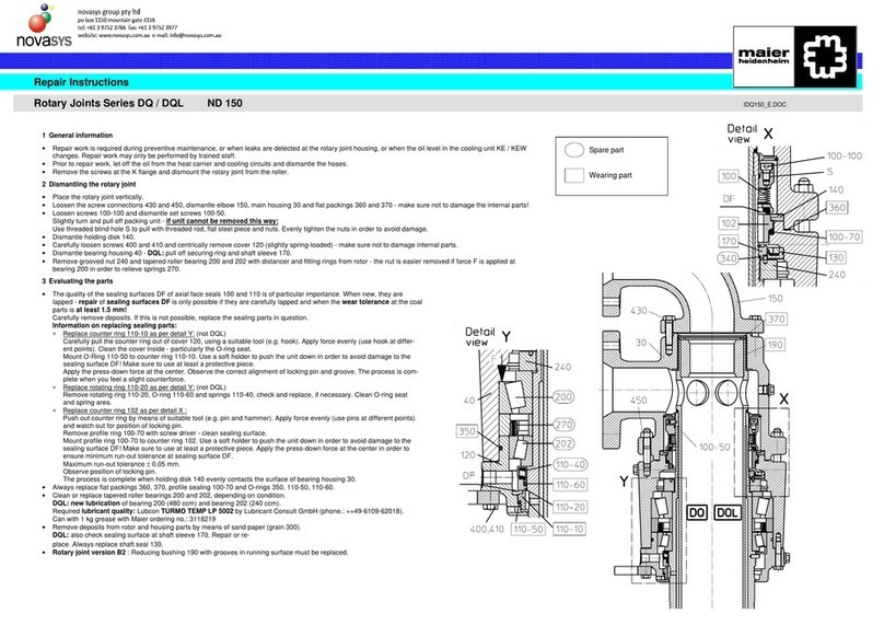
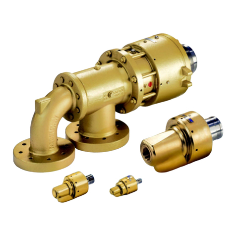
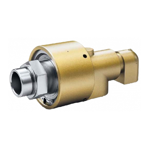
Maier H Series User manual

Operating Instructions for
Maier Rotary Joints
Series H / HW
Preface
Keep this manual for future reference.
Editor Christian Maier GmbH & Co. KG Maschinenfabrik
Würzburger Str. 67-69
D-89520 Heidenheim
Tel: +49 7321/317-0

Fax: +49 7321/317-139
E-Mail: [email protected]
Website: www.maier-heidenheim.de
Copyright © Christian Maier GmbH & Co. KG Maschinenfabrik
This manual including all parts of this manual is protected
by international copyright laws. Any use or modification of
this manual beyond the limits of the copyright laws is
prohibited and a legal offense without the consent of
Christian Maier GmbH & Co. KG Maschinenfabrik.
This applies, but is not limited to reproduction, translation,
microfilming and storing and processing in electronic
systems.

Section Contents Designation
1 General part of the operating instructions B
2 Specifications and spare parts S
3
For ATEX-certified products
(directive 2014/34/EC):
Additional information for use in hazardous areas (EX
areas)
A

Document identification
Title: Operating Instructions for Maier Rotary Joints
Document designation: B-H / HW_en
Document type: Translation of the original
Date of issue: 02/2020
Version: 14
List of modifications
Version index Comment Date Editor
14 25.02.2020 cma

Christian Maier GmbH & Co. KG
© 2019 by Christian Maier GmbH & Co. KG Maschinenfabrik. This document may not be copied or disclosed to third parties.
All rights, including copyright and property rights, reserved by Christian Maier GmbH Q Co. KG.
Operating Instructions _Series _H-HW_Part B_en – Version 10 – 01.09.2019
1 /57
B
B General Part of the Operating Instructions for Maier
Rotary Joints H / HW
1
Contents
1
General ......................................................................................................................................... 5
1.1
Information on this Manual ..................................................................................................... 5
1.2
Explanations and Symbols ....................................................................................................... 5
2
Product Description .................................................................................................................. 6
2.1
Intended Use ................................................................................................................................ 6
2.2
Reasonably Foreseeable Misuse ............................................................................................ 6
3.1
H1 / HW1 / R/L/K DN 15 … 100; HW1 Serie-450 /K DN15 … 25 .................................... 7
3.2
H2 / HW2 /R/L/K DN 15 … 100; HW2 Serie-450 /K DN 20 … 25 ................................. 8
3.3
HR2 / HWR2 /R/L/K DN DN 15 … 100; HWR2 Serie-450 /K DN 20 … 25 ................... 9
3.4
H3 / R/L/K DN 25 … 40 ........................................................................................................... 10
3.5
HWX2 / K - DN 32-50 ............................................................................................................. 11
3.6
HWX2 / K - DN 65-100 ............................................................................................................ 12
3.7
HWB2 / K DN 32 – 100 ............................................................................................................ 13
3.8
HWA2 / K DN 32 – 2099 ......................................................................................................... 14
3.9
HW1 Series-500 / K DN 32 – 100 .......................................................................................... 15
3.10
HWX2 Series -500 / K DN 32 – 50 ................................................................................... 16
3.11
HWX2 Series-500 / K DN 65-100 ......................................................................................... 17
3.12
HWB2 Series -500 / K DN 32 – 100 ................................................................................. 18
3.13
HWA2 Serie -500 / K DN 32-2099 .................................................................................. 19
4
Function ..................................................................................................................................... 20
5
Housing Connections ............................................................................................................. 20
5.1
One-Way Flow Design (single passage) ........................................................................ 20
5.1.1
Design 1 ................................................................................................................................... 20
5.2
Two-Way Flow Design (dual passage) ............................................................................... 21

Christian Maier GmbH & Co. KG
© 2019 by Christian Maier GmbH & Co. KG Maschinenfabrik. This document may not be copied or disclosed to third parties.
All rights, including copyright and property rights, reserved by Christian Maier GmbH Q Co. KG.
Operating Instructions _Series _H-HW_Part B_en – Version 10 – 01.09.2019
2 /57
B
5.2.1
Design 2 (Fig. 16) or X2 (Fig. 17) ....................................................................................... 21
5.3
Design R 2 ................................................................................................................................... 21
5.4
Design A 2 ................................................................................................................................... 21
5.5
Design B 2 ................................................................................................................................... 22
5.6
Three-Way Flow Design .......................................................................................................... 22
5.6.1
Design 3 ................................................................................................................................... 22
6
Rotor Connections .................................................................................................................. 23
6.1
Threaded Connection .............................................................................................................. 23
6.2
Flange Connection.................................................................................................................... 23
7
Safety .......................................................................................................................................... 24
7.1
Introduction ............................................................................................................................... 24
7.2
General Safety Information ................................................................................................... 24
7.3
Structure of the Safety Instructions ..................................................................................... 25
7.3.1
Signal Words .......................................................................................................................... 25
7.4
Pictograms Used ....................................................................................................................... 26
7.4 Authorized Staff ......................................................................................................................... 26
7.5 Risk Assessment and Residual Risks ...................................................................................... 27
8
Transportation an Storage .................................................................................................... 2 8
9
Information on Mounting and Operation ......................................................................... 28
9.1
For ATEX-certified Products (regulations 2014/34/EC) ................................................. 29
10
Installation ................................................................................................................................. 30
10.1
H2 / HW2 ..................................................................................................................................... 30
10.2
HR2 / HWR2 ........................................................................................................................... 30
10.3
H3 .............................................................................................................................................. 31
10.4
HWX2 DN 32-50 ................................................................................................................... 31
10.5
HWX2 DN 65-100 .................................................................................................................. 32
10.6
HWB2 ........................................................................................................................................ 32
10.7
HWA2 ........................................................................................................................................... 33

Christian Maier GmbH & Co. KG
© 2019 by Christian Maier GmbH & Co. KG Maschinenfabrik. This document may not be copied or disclosed to third parties.
All rights, including copyright and property rights, reserved by Christian Maier GmbH Q Co. KG.
Operating Instructions _Series _H-HW_Part B_en – Version 10 – 01.09.2019
3 /57
B
10.8
Mounting with Threaded Rotor........................................................................................ 33
10.9
Monting with K Flange [2] and Inner ring [3] .............................................................. 34
10.10
Aligning the Rotary Joint When Sealing is done by means of Flat Packing ....... 35
10.11
Permissible Concentricity Tolerances ............................................................................. 35
10.12
Connecting the Rotary Joint .............................................................................................. 36
11
General Information on Connection Lines ........................................................................ 37
12
Operation .................................................................................................................................. 40
12.1
Commissioning ......................................................................................................................... 40
12.2
During operation ................................................................................................................. 40
12.3
Troubleshooting .................................................................................................................... 41
13
Maintenance ............................................................................................................................. 41
13.1
Maintenance Plan .................................................................................................................... 42
14
Repair ......................................................................................................................................... 43
14.1
Repair Work ............................................................................................................................... 43
14.1.1
Dismounting the Rotary Joint from the Roller ............................................................ 43
15
Dismantling the Rotary Joint ................................................................................................ 44
15.1
H1 / HW 1 / R/L/K DN 15 … 100; HW1 Series-450 / K DN 15 … 25 ............................ 44
15.2
H2 / HW2 / R/LK DN 15 … 100; HW2 Series-450 / K DN 20 … 25 ........................ 45
15.3
HR2 / HWR2 /R/L/K DN 15 … 100; HWR2 Series-450 /K DN 20 … 25 ................. 46
15.4
H3 /R/L/K DN 25 … 40 ........................................................................................................ 47
15.5
HWX2 / K DN 32-50............................................................................................................ 48
15.6
HWX2 DN 65-100 ................................................................................................................. 49
15.7
HWB2 / K DN 32-100 ............................................................................................................... 50
15.8
HWA2 / K DN 32-2099 ....................................................................................................... 51
15.9
HW1 Series -500 / K DN 32-100 ....................................................................................... 52
15.10
HWX2 Series -500 / K DN 32-50 ...................................................................................... 53
15.11
HWX2 Series -500 / K DN 65-100 ................................................................................... 54
15.12
HWB2 Seies -500 / K DN 32-100 ...................................................................................... 55

Christian Maier GmbH & Co. KG
© 2019 by Christian Maier GmbH & Co. KG Maschinenfabrik. This document may not be copied or disclosed to third parties.
All rights, including copyright and property rights, reserved by Christian Maier GmbH Q Co. KG.
Operating Instructions _Series _H-HW_Part B_en – Version 10 – 01.09.2019
4 /57
B
15.13
HWA2 Series -500 / DN 32-2099 .................................................................................... 56
16
Assembly of the Rotary Joint ............................................................................................... 57
16.1
Requierment ............................................................................................................................... 57
16.2
Assembly ................................................................................................................................. 57

Christian Maier GmbH & Co. KG
© 2019 by Christian Maier GmbH & Co. KG Maschinenfabrik. This document may not be copied or disclosed to third parties.
All rights, including copyright and property rights, reserved by Christian Maier GmbH Q Co. KG.
Operating Instructions _Series _H-HW_Part B_en – Version 10 – 01.09.2019
5 /57
B
1 General
1.1
Information on this Manual
This manual is intended for use by the operators, the maintenance and the inspection staff. It is divided into the
following sections:
Section 1 "General Part of the Operating Instructions":
(pages with designation B)
This section provides general information on the manual, on safety and on handling the product.
Section 2 "Specifications and Spare Parts":
(pages with designation S)
This section provides product-specific data.
Section 3 "Additional Information for Use in Hazardous Areas (EX areas)":
(pages with designation A)
(only available for products certified as per directive 2014/34/EU)
Staff and operators must have read and fully understood the operating instructions and must observe all
instructions it contains. Please note that we will not be liable in any way for any damages and operational
disruptions resulting from the failure to read and/or observe the operating instructions.
Read chapter 7 and the specific safety instructions in the individual chapters with particular care.
We reserve the right to technical modifications if such modifications are required to improve the rotary joint or
its accessories, i.e. details and descriptions may differ from the information given in this manual.
1.2 Explanations and Symbols
Symbol Used for Explanation
● List List of facts and instructions. No specific sequence required.
1. Instructions consisting
of several individual
steps
Instructions consisting of several steps which must be
followed exactly in the sequence listed. Failure to observe
the instructions in the correct sequence may result in
damages or accidents.
[1] Item number Item number of the component mentioned in the
corresponding illustration.

Christian Maier GmbH & Co. KG
© 2019 by Christian Maier GmbH & Co. KG Maschinenfabrik. This document may not be copied or disclosed to third parties.
All rights, including copyright and property rights, reserved by Christian Maier GmbH Q Co. KG.
Operating Instructions _Series _H-HW_Part B_en – Version 10 – 01.09.2019
6 /57
B
2 Product Description
2.1 Intended Use
Maier Rotary Joints are only permitted to be used as fittings to connect pressurized pipes to rotating pressurized
systems. Typical examples of such rotating pressurized systems are rollers which are heated or cooled by means
of liquid, gas, or steam flowing through them. Please refer to the section "Specifications and Spare Parts" for
details on approved media, their grades and specifications. These specifications must be observed in the
application. Other media may be possible; please consult the manufacturer.
Never modify the rotary joint as this can cause hazards. Install, operate and maintain the rotary joint only as
described in these operating instructions. Company Maier will not be liable for any damages and operational
disruptions resulting from failure to read and/or observe the operating instructions.
These operating instructions do not contain all the information which is crucial for safe operation. In addition,
you are required to observe all national and local laws and regulations concerning the prevention of accidents,
applicable at the place of installation.
For repairs, use only genuine Maier spare parts or standardized components explicitly approved by Maier. Using
any other components can have adverse effects on the safety of the unit.
2.2 Reasonably Foreseeable Misuse
In case of reasonably foreseeable misuse of the product, the manufacturer's warranty will be void and the
operator will be fully responsible for the consequences.
Reasonably foreseeable misuse includes:
failure to observe the application data
failure to observe the medium specifications
failure to observe the maintenance intervals
failure to replace wearing parts
failure to perform maintenance work
faulty maintenance work
additional components mounted and conversions carried out without written approval
use of non-genuine spare parts

Christian Maier GmbH & Co. KG
© 2019 by Christian Maier GmbH & Co. KG Maschinenfabrik. This document may not be copied or disclosed to third parties.
All rights, including copyright and property rights, reserved by Christian Maier GmbH Q Co. KG.
Operating Instructions _Series _H-HW_Part B_en – Version 10 – 01.09.2019
7 /57
B
3 Components
3.1 H1 / HW1 / R/L/K DN 15 … 100; HW1 Serie-450 /K DN15 … 25
Figure 1
G 1 Housing 1
B Housing connection for the
medium
L Rotor
DR Sealing ring
DL Cover bushing
FD Flat packing
D Cover
KL Carbon bushing
DF Compression spring
SK Hexagon screw
AS Locking pin
SR Circlip
R Anti-rotation device

Christian Maier GmbH & Co. KG
© 2019 by Christian Maier GmbH & Co. KG Maschinenfabrik. This document may not be copied or disclosed to third parties.
All rights, including copyright and property rights, reserved by Christian Maier GmbH Q Co. KG.
Operating Instructions _Series _H-HW_Part B_en – Version 10 – 01.09.2019
8 /57
B
3.2 H2 / HW2 /R/L/K DN 15 … 100; HW2 Serie-450 /K DN 20 … 25
Figure 2
G 2 Housing 2
B,C Housing connection for the
medium.
L Rotor
DR Sealing ring
DL Cover bushing
FD Flat packing
D Cover
KL Carbon bushing
DF Compression spring
SK Hexagon screw
AS Locking pin
SR Circlip
R Anti-rotation device
IR Inner pipe (not included in the
scope of supply)

Christian Maier GmbH & Co. KG
© 2019 by Christian Maier GmbH & Co. KG Maschinenfabrik. This document may not be copied or disclosed to third parties.
All rights, including copyright and property rights, reserved by Christian Maier GmbH Q Co. KG.
Operating Instructions _Series _H-HW_Part B_en – Version 10 – 01.09.2019
9 /57
B
3.3 HR2 / HWR2 /R/L/K DN DN 15 … 100; HWR2 Serie-450 /K DN 20 … 25
Figure 3
G R2 Housing R 2
B,C Housing connection for the
medium
L Rotor
GL Slide bushing
DR Sealing ring
DL Cover bushing
FD Flat packing
D Cover
KL Carbon bushing
DF Compression spring
SK Hexagon screw
AS Locking pin
SR Circlip
R Anti-rotation device
IR Inner pipe (not included in the
scope of supply)

Christian Maier GmbH & Co. KG
© 2019 by Christian Maier GmbH & Co. KG Maschinenfabrik. This document may not be copied or disclosed to third parties.
All rights, including copyright and property rights, reserved by Christian Maier GmbH Q Co. KG.
Operating Instructions _Series _H-HW_Part B_en – Version 10 – 01.09.2019
10 /57
B
3.4 H3 / R/L/K DN 25 … 40
Figure 4
G 3 Housing 3
B,C Housing connection for the
medium
L Rotor
VV Vacuum valve
CU CU seal
DR Sealing ring
DL Cover bushing
FD Flat packing
D Cover
KL Carbon bushing
DF Compression spring
SK Hexagon screw
AS Locking pin
SR Circlip
R Anti-rotation device
IR Inner pipe (not included in the
scope of supply)

Christian Maier GmbH & Co. KG
© 2019 by Christian Maier GmbH & Co. KG Maschinenfabrik. This document may not be copied or disclosed to third parties.
All rights, including copyright and property rights, reserved by Christian Maier GmbH Q Co. KG.
Operating Instructions _Series _H-HW_Part B_en – Version 10 – 01.09.2019
11 /57
B
3.5 HWX2 / K - DN 32-50
Figure 5
G Housing KL Carbon bushing
B,C Housing connection for the medium DF Compression spring
L Rotor SK-1 Hexagon screw 1
K-X1 Elbow 1 (HWX2 DN 32-50) SK-2 Hexagon screw 2
DS Thrust washer AS Locking pin
DR Sealing ring SR Circlip
DL Cover bushing VS Screw plug
FD-1 Flat packing 1 CU CU seal
FD-2 Flat packing 2 R Anti-rotation device
D Cover IR Inner pipe (not included in the
scope of supply)

Christian Maier GmbH & Co. KG
© 2019 by Christian Maier GmbH & Co. KG Maschinenfabrik. This document may not be copied or disclosed to third parties.
All rights, including copyright and property rights, reserved by Christian Maier GmbH Q Co. KG.
Operating Instructions _Series _H-HW_Part B_en – Version 10 – 01.09.2019
12 /57
B
3.6 HWX2 / K - DN 65-100
Figure 6 Cover Bushing [DL] and Locking Pin [AS-2] DN 75-100
G Housin
g
ZS-1 Socket head screw 1
Abbildung 6-1
Figure 6.1
CBhi[DL]
B,C Housin
g
connection for the medium ZS-2 Socket head screw 2
L Rotor VS-2 Screw
p
lu
g
2
K-X2 Elbow 2
(
HWX2 DN 65-100
)
CU-2 CU-seal 2
DS Thrust washer R Anti-rotation device
DR Sealin
g
rin
g
IR Inner pipe (not included in
the sco
p
e of su
pp
l
y)
DL Cover bushin
g
FD-1 Flat
p
ackin
g
1
FD-2 Flat
p
ackin
g
2
D Cover
KL Carbon bushin
g
DF Com
p
ression s
p
rin
g
SK-1 Hexa
g
on screw 1
SK-2 Hexa
g
on screw 2
AS-1 Lockin
g
p
in 1
AS-2 Lockin
g
p
in 2
SR Circli
p
VS-1 Screw
p
lu
g
1
CU-1 Sealin
g
rin
g
1
KM Clamp nut

Christian Maier GmbH & Co. KG
© 2019 by Christian Maier GmbH & Co. KG Maschinenfabrik. This document may not be copied or disclosed to third parties.
All rights, including copyright and property rights, reserved by Christian Maier GmbH Q Co. KG.
Operating Instructions _Series _H-HW_Part B_en – Version 10 – 01.09.2019
13 /57
B
3.7 HWB2 / K DN 32 – 100
G Housing
Figure 7-1
Cover Bushing [DL] and
Locking Pin [AS-2]
DN 75-100
B,C Housing connection for the medium
L Rotor
BU Bushing
K Elbow
DS Thrust washer
DR Sealing ring
DL Cover bushing
FD-1 Flat packing 1
FD-2 Flat packing 2
D Cover
KL Carbon bushing
DF Compression spring
SK-1 Hexagon screw 1
SK-2 Hexagon screw 2
AS-1 Locking pin 1
AS-2 Locking pin 2
SR-1 Circlip 1
SR-2 Circlip 2
VS Screw plug
CU CU seal
R Anti-rotation device
IR Inner pipe (not included in the scope of supply)
Figure 7 Cover Bushing [DL] DN 32-65

Christian Maier GmbH & Co. KG
© 2019 by Christian Maier GmbH & Co. KG Maschinenfabrik. This document may not be copied or disclosed to third parties.
All rights, including copyright and property rights, reserved by Christian Maier GmbH Q Co. KG.
Operating Instructions _Series _H-HW_Part B_en – Version 10 – 01.09.2019
14 /57
B
3.8 HWA2 / K DN 32 – 2099
Figure 8 Cover Bushing [DL] DN 32-65
G Housing CU CU seal
Figure 8-1
Cover Bushing [DL] and
Locking Pin [AS-2]
DN 75-2099
B,C Housing connection for the
medium R Anti-rotation device
L Rotor IR Inner pipe (not included
in the scope of supply)
BU Bushing
K Elbow
DR Sealing ring
OR-1 O-ring 1
OR-2 O-ring 2
DL Cover bushing
FD-1 Flat packing 1
FD-2 Flat packing 2
D Cover
KL Carbon bushing
DF Compression spring
SK-1 Hexagon screw 1
SK-2 Hexagon screw 2
AS-1 Locking pin 1
AS-2 Locking pin 2
SR-1 Circlip 1
SR-2 Circlip 2
VS Screw plug

Christian Maier GmbH & Co. KG
© 2019 by Christian Maier GmbH & Co. KG Maschinenfabrik. This document may not be copied or disclosed to third parties.
All rights, including copyright and property rights, reserved by Christian Maier GmbH Q Co. KG.
Operating Instructions _Series _H-HW_Part B_en – Version 10 – 01.09.2019
15 /57
B
3.9 HW1 Series-500 / K DN 32 – 100
Figure 9
G 1 Housing 1
B Housing connection for the medium
L Rotor
FS Flange with neck
LF Slip flange
DR Sealing ring
DL Cover bushing
FD-1 Flat packing 1
FD-2 Flat packing 2
D Cover
KL Carbon bushing
DF Compression spring
SK Hexagon screw
AS Locking pin
SR Circlip
R Anti-rotation device

Christian Maier GmbH & Co. KG
© 2019 by Christian Maier GmbH & Co. KG Maschinenfabrik. This document may not be copied or disclosed to third parties.
All rights, including copyright and property rights, reserved by Christian Maier GmbH Q Co. KG.
Operating Instructions _Series _H-HW_Part B_en – Version 10 – 01.09.2019
16 /57
B
3.10 HWX2 Series -500 / K DN 32 – 50
G Housin
g
CU CU seal
B,C Housin
g
connection for the medium R Anti-rotation device
L Rotor IR Inner pipe (not included in the scope of
su
pp
l
y)
FS-1 Flan
g
e with neck 1
LF-1 Sli
p
flan
g
e 1
FS-2 Flan
g
e with neck 2
LS-2 Sli
p
flan
g
e 2
K-X1 Elbow X1
(
HWX DN 32-50
)
DS Thrust washer
DR Sealin
g
rin
g
DL Cover bushin
g
FD-1 Flat
p
ackin
g
1
FD-2 Flat
p
ackin
g
2
FD-3 Flat
p
ackin
g
3
FD-4 Flat
p
ackin
g
4
D Cover
KL Carbon bushin
g
DF Com
p
ression s
p
rin
g
SK-1 Hexa
g
on screw 1
SK-2 Hexa
g
on screw 2
AS Lockin
g
p
in
SR Circli
p
VS Screw
p
lu
g
Figure 10
This manual suits for next models
1
Table of contents
Other Maier Plumbing Product manuals
Popular Plumbing Product manuals by other brands

Pfister
Pfister Selia F-034-4SL Quick installation guide

Vogue
Vogue GL280 instruction manual

Hansa
Hansa Concerto Installation and maintenance guide

Spectrum Brands
Spectrum Brands Pfister Pfirst Series G529-PF1 Quick installation guide

Alpine Saunas
Alpine Saunas OSLO Installation & owner's manual

PEERLESS
PEERLESS PTT14165 Series manual

Homewerks
Homewerks 3190-43-CH-BC-Z quick start guide

Olympia
Olympia L-6160 installation manual

American Standard
American Standard Williamsburg 3770 installation instructions

Viega
Viega 6960 Instructions for use

TLV
TLV VS1C instruction manual

VADO
VADO AXCES ASTRA AX-AST-136/CD-CP Installation & user manual