maimin ROTOSHERE10 Datasheet

MAIMIN°
ROTOSHERE10
Instructions
&
Parts
List
Catalog
1.
SAFETY INSTRUCTIONS
a.
Be
sure machine
is
properly grounded.
b.
Use
correct electrical wiring.
c.
Keep cutting area clean and well lit.
d. Keep visitors away from cutting area.
e.
Do not use machine in damp or wet location.
f.
Store machine in dry location.
g.
Keep machine clean and blade sharp for best and
safest performance.
h. Always disconnect machine when not in use, before
servicing, and when changing blade.
i.
Remove key from knife lock before starting motor.
j.
Avoid accidental starting by disconnecting electrical
cord before carrying machine and making sure switch
is
offbefore connecting cord.
k. Keep hands away from blade.
©1978
H.
MAIMIN CO., INC.
2.
TOSTART
Be
sure voltage at the electrical outlet
is
the same
as
that
stamped on the nameplate
of
the machine. With Switch
10717 in the
"off"
position, attach Connector 458B to
Terminal Pins 309C. To start motor, flip Switch 10717
to
"on"
position (or squeeze Momentary Switch 10716). The
Knife Guard 10609 acts
as
a protective guard for the
operator
so
that it should be down when the machine
is
not
in use. The bottom
of
the Knife Guard should only be
slightly above the
top
of
the lay in order to prevent the
operator's hand from accidentally touching the blade.
3.
TO
SHARPEN BLADE
30329
With motor running, press Sharpener Trigger 10619 until
Stone 330P turns against the Blade. Hold the Stone against
the Blade for about 5 seconds to sharpen a keen cutting
edge.
(Continued
on
page
4)
From the library of: Superior Sewing Machine & Supply LLC

10779
120
v.
10780
220
v.
Worm
Assembly
10643
Assembly 10606
ROTOSHERE
10
MOTOR
&
STANDARD
ASSEMBLY
10667
10668
Baseplate Assembly
10608
10709
10750;;:;
10751 /
~
10717
Sfi~,
~ 10773
1_m"''
J10661
i
428T
10777 120v
10778
220v.
Standard
Assembly
10602
/10423
10656
~----10700
--~=~---10671
..._..Jt::'§>}------10657
ALWAYS GIVE MACHINE SERIAL NUMBER WHEN ORDERING PARTS
2
10714
}
Motor
Assembly
15094
120
v.
15095
220v.
lj
Assembly
10655
From the library of: Superior Sewing Machine & Supply LLC

PARTS
LIST
PART
PART
NO.
DESCRIPTION
NO. DESCRIPTION
309C Terminal Pin 10656
Throat
Plate
only
309E
Nut
10657 Counter-Cutting Blade
309G Washer 10661
Axle
Assembly (w/shells & pins)
315AS Screw 6 x
3/4
Fil. Hd. 10662 Axle
330A
Bushing 10663 Roller Shell
330C
Nut
for
Bushing 10664 Washer
3300
Cone
Nut
10665 Roller Pin
330E
Nut
10667 Bushing
330P Stone
only
10668 Screw
M3
x 0,5 x 8 Fil. Hd.
340
Screw 10 x
1/8
M Hd. 10669 Baseplate
only
400T
Screw 6 x
1/8
Binding Hd. 10671 Spring
428T
Screw 10680 Handle, Wiper
4588
Connector, Grounded 10681 Housing, Wiper
803
Screw
1/4
x 1 Flat
Cap
10682 Compression Spring
822S Screw 6 x
1/4
Binding Hd. 10683 Plunger
10250 Bearing 10684
Pad
10301 Retaining Ring 10685 Shoulder Screw
10302 Washer 10700 Screw
M3
x
0,5
x 6
Pan
Hd.
10303 Undulated Washer 10703 Screw
M5
x 8 Flat Hd. Socket
10304 Screw M4 x
0,
7 x 8 Socket Hd. 10705 Scraper
10324 Rollpin 10706 Clamp
10325 Retaining Ring 10707 R10 Handle Assembly
(w/10716)
10423 Screw
M3
x 0,5 x 8
Flat
Hd. 10709 Trigger
10428 Coupling 10710 R10 Handle Assembly
(w/10717)
10602 Standard Assembly
(w/10628,
10609, 10643, 10711 R10 Terminal Block Assembly
(w/10714,
10705, 10706)
10644,309C)
10603 Standard
with
1
0639
Gear Shaft 10714 Terminal
Block
Cover
10606 Sharpener Assembly
(w/10611,
10619, 10622) 10716 Momentary Switch (Squeeze type)
10607
Knife
Lock 10717 Switch
10608 Baseplate Assembly (w/10655, 10661) 10720 Worm
10609
Knife
Guard
10723
Screw
M3
x 6 Flat Hd.
10610 Blade Wiper Assembly 10750 Carbon Brush
10611 Bracket 10751 Brush
Cap
10614 Bushing 10769 Screw
M5
x 10
Pan
Hd.
10615 Washer 10773 Screw
10617 Spring, Outer 10774
Cap
10618 Shaft
10776
Top
Housing
10619 Sharpener Trigger 10777 Field, 120
v.
10620
Washer
10778 Field, 220
v.
10621 Spring, Inner 10779 Armature, 120
v.
10622 Stone Assembly 10780 Armature, 220
v.
10628 Gear Assembly 10781 Fan Washer
10630 Washer 10782 Fan
10631 Gear Screw M4 x 0.7 x
10
Flat Hd. 10784 Undulated Washer
10632 Felt
Seal
10785 Washer
10637
Nut
10786 Retaining Ring
10638
Grease
Fitting
10787
Bottom
Housing
10639 Gear Shaft 10788 Assembly
Bolt
.10640
Cap
10789
Washer
10643 Worm Assembly (w/shaft,
spac8rs
& bearings) 15094 R10
Motor
Assembly, 120 volts
10644 Screw M4 x
0,
7 x 10 Socket Hd. 15095 R10
Motor
Assembly, 220 volts
10647 Worm Shaft 15124 Bearing,
bottom
10648 Bearing Spacer 30329 Blade R10
10649 Spacer Parts
Not
Illustrated
10655 Throat Plate Assembly (w/1 0657, 10671,
327K
Knife Key
10423, 10700) 22028
Grease
3
From the library of: Superior Sewing Machine & Supply LLC

4.
TO
LUBRICATE PAD
10684
Use
light weight oil (#10 weight) to saturate Pad 10684
in Blade Wiper Assembly 10610. Hole for oiling
is
in Wiper
Housing 10681.
5. TO LUBRICATE
GEAR
AND
WORM
ASSEMBLIES
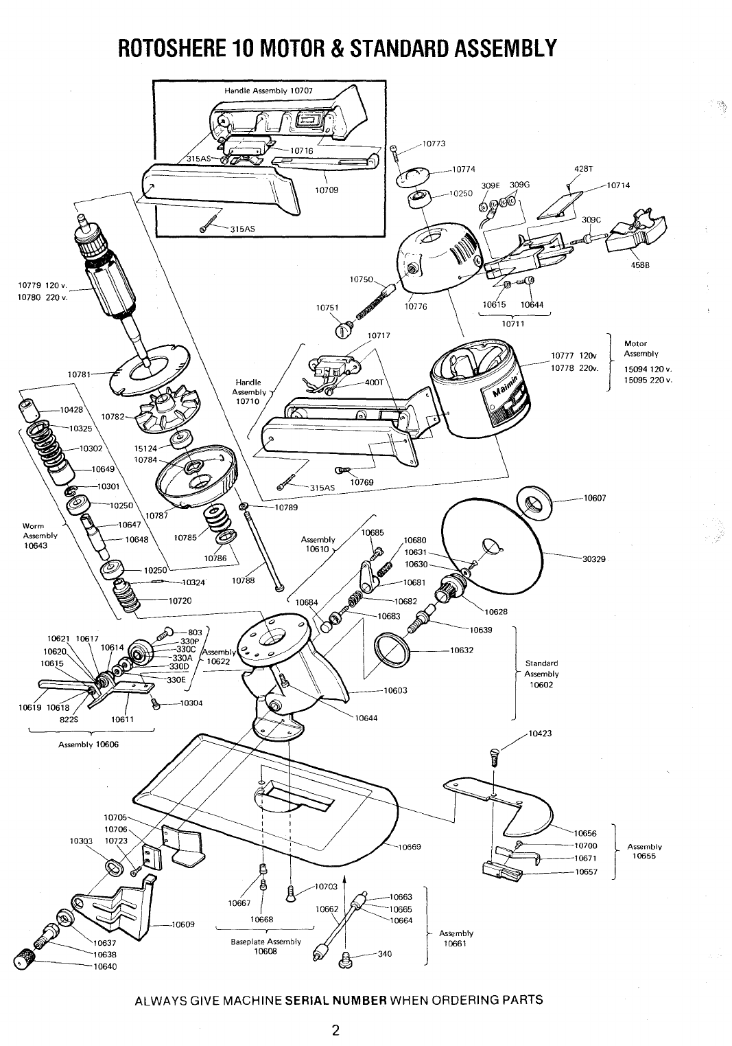
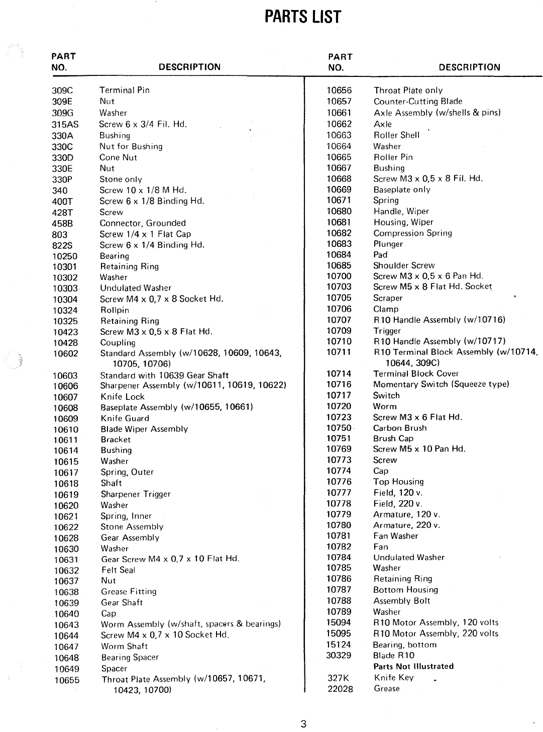
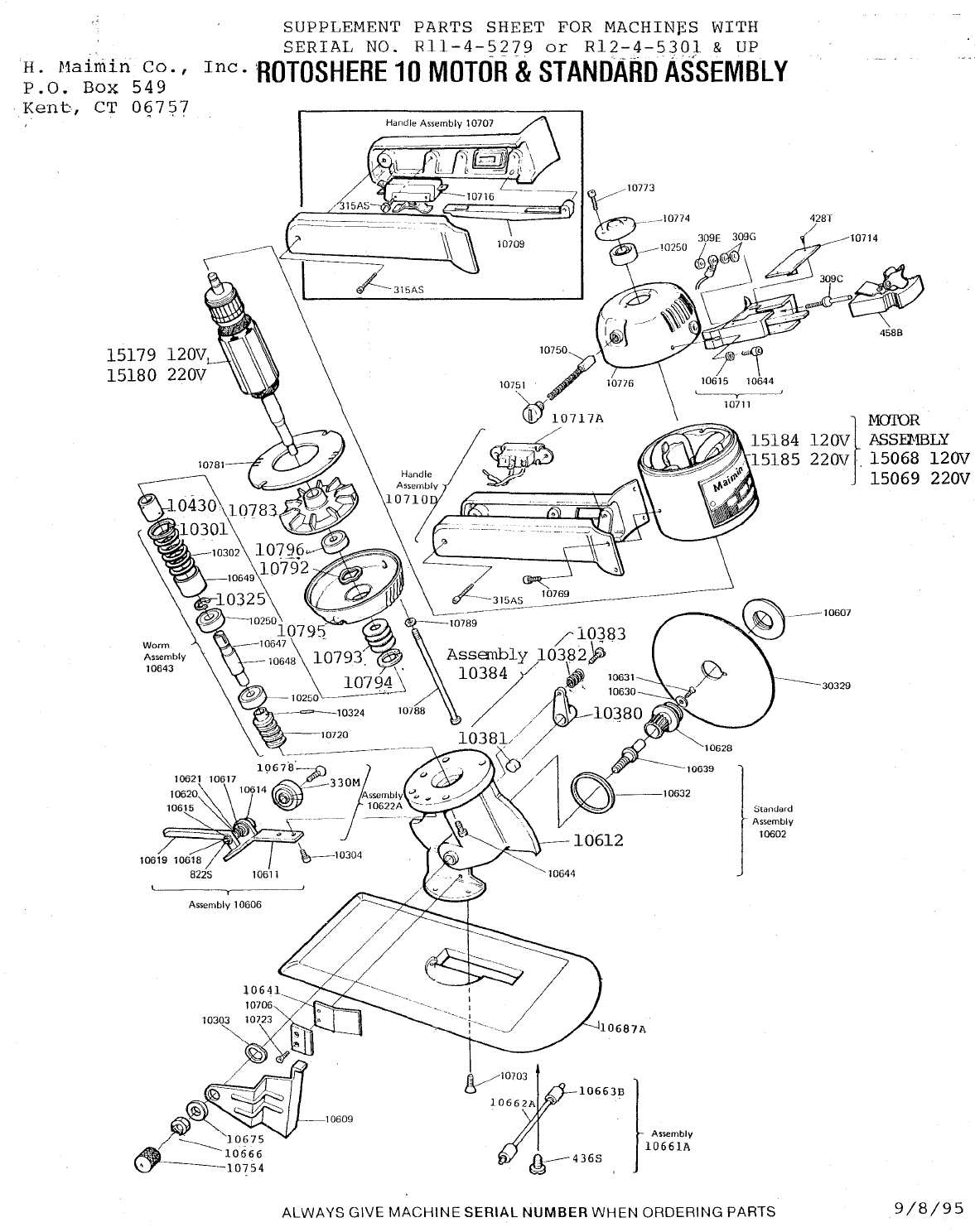
Grease the Gear Assembly 10628 and
Worm
Assembly
10643 monthly
by
turning Cap 10640 one full turn. When
the Cap
is
empty, refill it with Maimin Grease 22028 or
Lubriplate 930-AA.
6. MAINTENANCE SCHEDULE
a) Daily: -Oil Pad I0684
b)
Monthly:-
Grease Gear and Worm Assemblies
Clean motor with compressed air
c) Semi-annually:
-Check
Carbon Brushes 10750
Blow out Roller Shells 10663 with
compressed air (do not oil Roller
Pins 10665)
7.
TO
CHANGE BLADE
30329
Detach Connector 458B, and
io~er
Knife Guard 10609.
Lay the machine on its side. Pull up Blade Wiper Assembly
10610, and rotate it above the Blade. Insert Knife Key
327K into Knife Lock 10607 and turn counter-clockwise
to loosen. Remove Knife Lock. While pulling Throat
Plate Assembly 10655 towards you, pull Blade upwards
and out. Slip new Blade into place, seating it
on
pin
of
gear. Replace Knife Lock, and tighten with Knife Key.
4
8.
TO
CHANGE STONE ASSEMBLY
10622
Depress Sharpener Trigger 10619
to
expose the thin shoul-
der next to Nut 330E. Hold this shoulder with pliers, and
insert 5/32" Hex Key 22064 into Screw 803. Turn Hex
Key to unscrew and remove Stone Assembly. Replace with
new Stone Assembly, and tighten.
9.
TO
CHANGE CARBON BRUSH
10750
Unscrew Brush Cap 10751. Pull out Carbon Brush, and
replace with new one.
10.
TO
REMOVE WORM ASSEMBLY 10643
Take
off
Blade 30329. Remove motor by unscrewing the
four screws 10644, and then take
off
Sharpener Assembly
10606 by unscrewing the two screws 10304. Take out
Coupling 10428 and then the Retaining Ring 10325 from
the top
of
the Standard 10603. Remove Washers 10302.
Pull out
Worm
Assembly 10643.
11.
TO
REMOVE
GEAR
ASSEMBLY
10628
First take out Worm Assembly
as
described in para. 10.
Remove Gear Screw 10631 and Washer 10630. Pull out
Gear Assembly 10628. Do
not
try
to remove Gear Assem-
bly
without
removing Worm Assembly first!
CAUTION:
DO
NOT REMOVE GEAR
SHAFT 10639 FROM STANDARD
10603
AS
SHAFT
IS
POSITIONED
AT
THE FACTORY WITH
SHIMS
FOR CORRECT ALIGNMENT OF THE
GEAR AND
WORM.
H.
MAIMIN
CO.,
INC.
575
EIGHTH AVENUE,
NEW
YORK, N.Y.
10018
U.S.A.
Printed
in
U.S.A.
R105783
From the library of: Superior Sewing Machine & Supply LLC

IMPORTANT
SAFETY
INSTRUCTIONS
When
using
your
cutting
machine,
basic
safety
Instructions
should
always
be
followed
including
u-
....
following:
This
cuHi"g
mach/no
Is
for
commercial
uso
only.
Road
all
Instructions
boforo
using.
DANGER--To
reduce
the
risk
of
electric
shock:
1.
Do
not
Install
or
store
this
machine
in
a
wet
location.
WARNING--To
reduce
the
risk
of
burns,
fire,
electric
shock,
or
Injury
to
persons:
1. Use
machine
only
for
its
Intended
use
as
a
portable
cutting
machine.
2.
Turn
machine
to
"OFF"
(0)
before
connecting
or
disconnecting
power
cord.
3.
Connect
this
machine
to
a
properly
grounded
outlet
only.
See
Grounding
Instructions.
4. Always
disconnect
electrical
connector
from
machine
when
not
using
it,
before
servicing
it,
or
changing
blade.
5.
Do
not
leave
machine
unattended
while
it Is
connected
to
power
outlet.
6.
Do
not
operate
machine
with
a
damaged
cord
or
if
machine
has
been
dropped.
Do
not
disassemble--
take
to
a
qualified
serviceman
for
repairs.
Incorrect
assembly
can
cause
electric
shock
when
the
machine
Is
used.
7.
Keep
hands
and
fingers
away
from
blade
and
moving
parts.
6.
Keep
guards
in
place and In
working
order.
9.
The
knife
key
and
other
wrenches
must
be
removed
from
machine
before
starting
motor.
10.
Keep
ventilation
openings
of
machine
free from
dust
and
lint
..
11.
Keep
machine
clean
and
blade
sharp
for
best
and
safest
performance.
SAVE THESE
INSTRUCTIONS
GROUNDING
INSTRUCTIONS
This
machine
must
be
grounded.
In
the
event
of
malfunction
or
breakdown,
grounding
provides
a
path
of
least
resistance
for
electric
current
to
reduce
the
risk
of
electric
shock.
This
machine
is
equipped
with
a
Ground
Shield
surrounding
the
Terminal
Pins;
this
Ground
Shield
is
designed
to
be
used
with
e.
Malmln
Grounded
Connector,
part
number
458A
or
4589.
See
wiring
Instructions
supplied
with
the
Connector.
DANGER--
Improper
connection
of
the
Maimin
Connector
can
result
In
a
risk
of
electric
shock.
Check
with
a
qualified
electrician
or
serviceman
if
the
grounding
instructions
are
not
completely
understood
or
if
in
doubt
as
to
whether
the
machine
is
properly
grounded.
Do
not
modify
the
Ground
Shield
provided
with
this
machine.
Use
correct
wire
sizes
with
the
Maimin
Grounded
Connector.
U.S.A
only:
1
phase:
Use
AWG
16/3
SJ,
SJT
or
SJE
3
phase:
Use
AWG
16/4
SJ,
SJT
or
SJE
INTERNATIONAL: 1
P+N+
: Use 3 X
1,,0
mm
CEE
(2) 61
3P+
:
Use
4 X 1
~-
0
mm
GEE (2)
61
H. MAIMIN CO., INC. P.O.
Box
549, Route 341, Kent, CT 06757
Safety2.PUB Printed In
U.S.A
From the library of: Superior Sewing Machine & Supply LLC

SUPPLEMENT PARTS SHEET
FOR
MACHIN~S
WITH
SERIAL
NO.
Rll-4-5279
or
Rl2-4-5301
&
UP
H.
Haimin
Co.'
Inc.
HOTOSHERE
10
MOTOR
&
STANDARD
ASSEMBLY
P.O.
Box
549
Kent,
CT
097~7
Worm
Assembly
10643
10621
10611
Assembly 1
0606
Handle Assembly 10707
10709
10751 10776
''1J
10717A
s6
l0663B
t
Assembly
l0661A
------30329
J
lStandard
Assembly
10602
ALWAYS
GIVE
MACHINE
SERIAL
NUMBER
WHEN
ORDERING PARTS
9/8/95
From the library of: Superior Sewing Machine & Supply LLC

H.
Maimin
Co.,
Inc.
P.O.
Box
549
Kent,
CT
06757
U.S.A.
Part
No.
10301
10325
10380
10381
10382
10383
10384
10430
10612
10622A
10661A
l0662A
l0663B
10666
10675
10678
107100
10717A
10754
10783
10792
10793
10794
10795
15179
15180
15184
15185
330K
330M
PARTS
LIST
Description
Retaining
Ring
Retaining
Ring
Oiler
Felt
Spring
Shoulder
Screw
Oiler
Assembly
Coupling
Assembly
Standard
with
10639
Gear
Shaft
Stone
Assembly
Axle
Assembly
Axle
Needle
Roller
Nut,
M5
Hex
Washer
Stone
Shaft
RlO
Handle
Assembly
(w/10717A)
Rocker
Switch
Cup
Nut,
M8
Fan
Undulated
Washer
Washer
Retaining
Ring
Bottom
Housing
Armature
Rl1-3
120V.
Armature
Rl2-3
220V.
Top
Housing
&
Field
Assembly
120V.
Top
Housing
&
Field
Assembly
220V.
Stone
Retaining
Ring
(Not
Shown)
Stone
w/Bushing
The
following
parts
for
the
Rotoshere
10
differ
from
those
illustrated
in
the
Rotoshere
10
Parts
List:
10758A
10755
10855
340S
10673A
10658
10687A
436S
436W
10641
Cutting
Guide
w/Carbide
Blade
Spring
Spacer
Screw
RlO
Baseplate
Assembly
Shim-Rear
Axle
Baseplate
w/Guide
Support
Screw-Front
&
Rear
Axle
Washer-Front
&
Rear
Axle
Scraper
9/8/95
From the library of: Superior Sewing Machine & Supply LLC

H.
Maimin
Co.,
Inc.
P.O.
Box 549
Kent,
CT.
06757
U.S.A.
SUPPLEMENT
PARTS
SHEET
FOR
ROTOSHERE
10
MACHINES
WITH
SERIAL
NO.
Rll-4-5100/R12-4-5074
&
UP
USING
BLACK
MOTOR.
PART
NO.
10769A
10785
10786
10793
10794
10796
1192
15068A
15069A
15124
15179A
15180A
15314
15315A
15316
15317
15319
15320
15321
15322
15323
15325
15326
15327
15328
15330
DESCRIPTION
Screw,
M5X8mm
Cheese
Hd.
(4)
Washer,
.860
X
.343
X
.010
Retaining
Ring,
Top
Washer,
1.020
X
.406
X
.010
Retaining
Ring,
Bottom
Bearing,
Bottom
Screw,
10-32Xl/4
Knurled
Cup
Point
Soc.
Set
Motor,
Rll-4
120V.
Motor,
Rl2-4
220V.
Bearing,
Top
Armature,
Rll-4
120V.
Armature,
Rl2-4
220V.
Rubber
Grommet
Bottom
Housing
Top
Housing
Field,
Rll-4
l20V.
Brush
Holder
Screw,
10-32X3
1/4
Phillips
Flat
Hd.
(2)
Brush
Brush
Cap
Fan
Field,
Rl2-4
220V.
Washer,
1.020
X
.625
X
.010
Undulating
Washer,
Top
Retaining
Ring,
Armature
Screw,
10-32
X
5/8
Hex
Washer
Hd.
(2)
Always
give
machine
SERIAL
NUMBER
when
ordering
parts.
2/15/95
From the library of: Superior Sewing Machine & Supply LLC
Table of contents