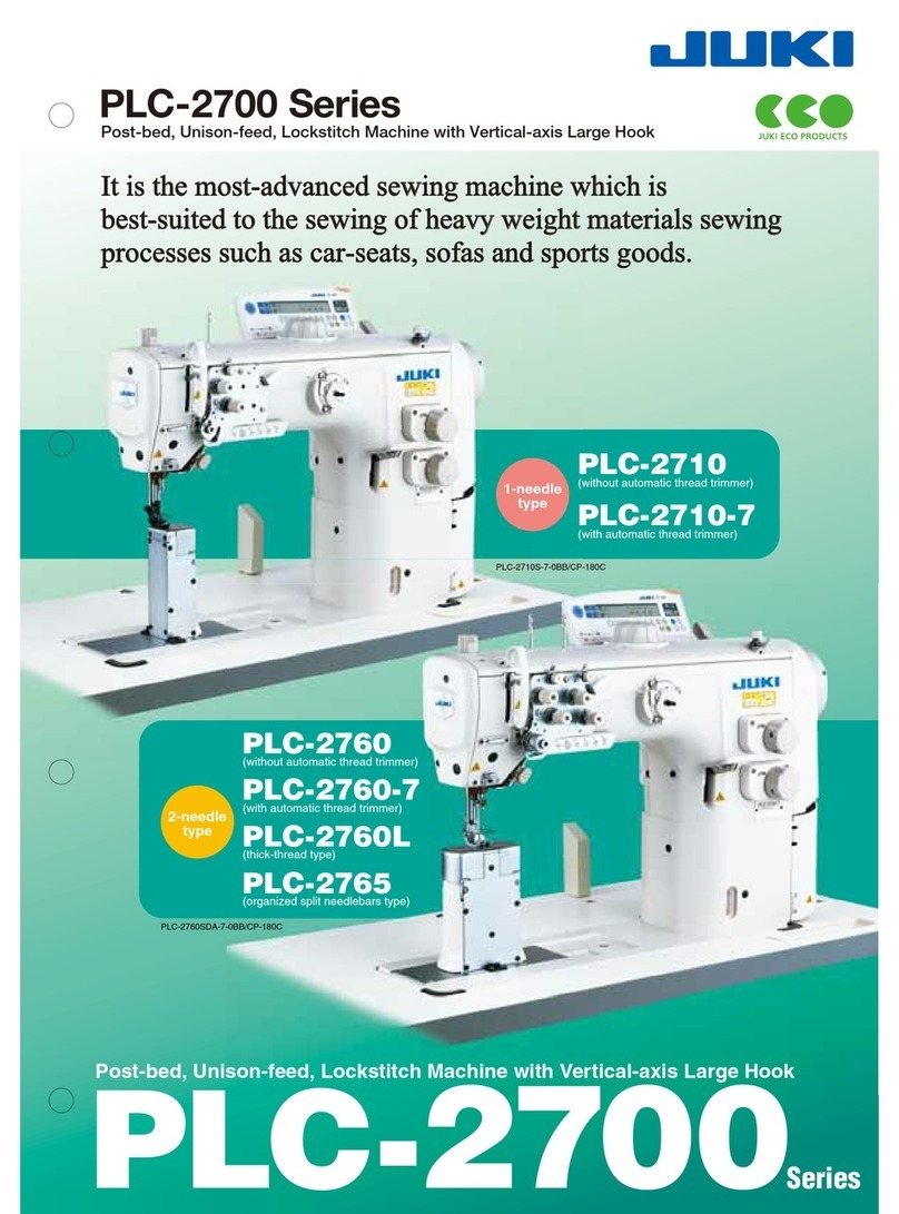
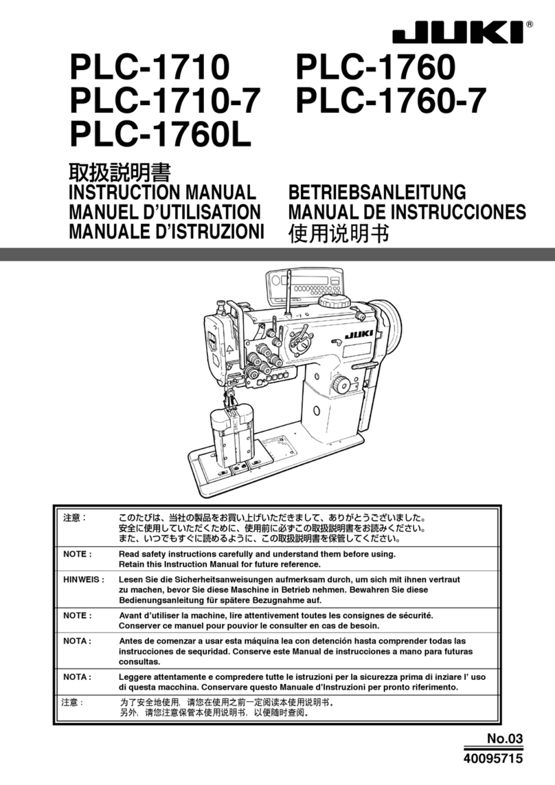
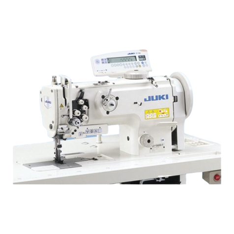
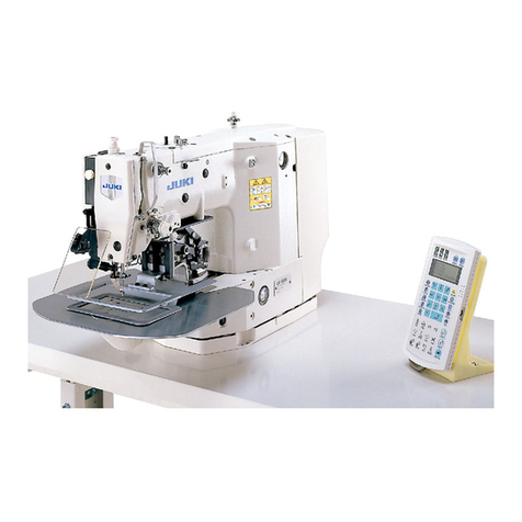
JUKI PLC-2700 Series User manual

PLC-2700 Series
INSTRUCTION MANUAL

i
CONTENTS
1. SPECIFICATIONS......................................................................................................... 1
2. INSTALLATION............................................................................................................. 4
2-1. Installation of the sewing machine................................................................................................4
2-2. Adjusting the belt tension (PLC-2710, 2760, 2760L, 2765) ..........................................................6
2-3. Pneumatic components..................................................................................................................7
2-4. Attaching the belt cover (PLC-2710, 2760, 2760L, 2765) .............................................................9
2-5. Installing the thread stand ........................................................................................................... 10
2-6. Installing the thread guide pin.....................................................................................................10
3. PREPARATION OF THE SEWING MACHINE .......................................................... 11
3-1. How to set the model of the machine head ................................................................................ 11
3-2. Adjusting the machine head
(PLC-2710-7, 2760-7).......................................................................... 13
3-3. Installing the detector (PLC-2710, 2760, 2760L, 2765; when the option kit is used) .............. 15
3-4.
Opening/closing the hook cover.................................................................................................. 17
3-5. Lubrication.....................................................................................................................................17
3-6. Attaching the needle.....................................................................................................................20
3-7. Attaching and removing the bobbin............................................................................................ 21
3-8. Threading the hook.......................................................................................................................22
3-9. Winding a bobbin..........................................................................................................................23
3-10. Threading the machine head ..................................................................................................... 24
4. ADJUSTING THE SEWING MACHINE ..................................................................... 27
4-1. Adjusting the stitch length...........................................................................................................27
4-2. Thread tension .............................................................................................................................. 28
4-3. Thread take-up spring .................................................................................................................. 29
4-4. Needle-to-hook relation................................................................................................................30
4-5. Adjusting the hook needle guard ................................................................................................31
4-6. Adjusting the bobbin case opening lever...................................................................................31
4-7. Position of the counter knife and adjustment of the knife pressure........................................ 32
4-8. Adjusting the pressure of the presser foot ................................................................................32
4-9.
Adjusting the amount of the alternating vertical movement of the walking foot and the press-
er foot .................................................................................................................................................... 33
5. OPERATION OF THE SEWING MACHINE................................................................ 34
5-1. Hand lifter ...................................................................................................................................... 34
5-2. Resetting the safety clutch .......................................................................................................... 34
5-3. Fixing the feed adjusting dial.......................................................................................................35
5-4. Normal-/reverse-feed stitch needle entry points alignment at the time of automatic re-
verse feed stitching ..................................................................................................................... 36
5-5. Operation switches (PLC-2710-7, 2760-7)...................................................................................37
5-6. Organized split needle bar (PLC-2765) ....................................................................................... 39
5-7. Knee switch (PLC-2710-7, 2760-7)...............................................................................................40
6. SEWING SPEED TABLE ............................................................................................ 43
7. MOTOR PULLEY AND V-BELT.................................................................................. 43
8. TROUBLES IN SEWING AND CORRECTIVE MEASURES...................................... 44
– 1 –
1. SPECIFICATIONS
No. Item Application
1 Model PLC-2710 PLC-2760
2 Model name Post-bed, 1-needle, unison-feed,
lockstitch machine with vertical-axis
large Hook
Post-bed, 2-needle, unison-feed,
lockstitch machine with vertical-axis
large Hook
3 Application Medium- to heavy-weight materials, car seat, furniture
4 Sewing speed Max. 2,500 sti/min
(See "6. SEWING SPEED TABLE" p.43.)
5 Needle GROZ-BECKERT 135 x 17 (Nm 100 to Nm 180) (Standard : Nm 140)
6 Applicable thread size for
sewing
#30 to #5
7 Applicable thread size to
be cut
8 Stitch length Max. 12 mm (forward/reverse feed)
9 Stitch length dial 1-pitch dial
10 Presser foot lift Hand lifter : 10 mm
Knee lifter : 20 mm
11 Stitch length adjusting
mechanism
By dial
12 Reverse stitch adjusting
method
By lever
13 Thread take-up Link thread take-up
14 Needle bar stroke 40 mm
15 Amount of the alternate
vertical movement
1 mm to 9 mm (Alternate vertical dial adjustment type)
16 Hook Vertical-axis 2-fold hook (Latch type)
17 Feed mechanism Box feed
18 Top and bottom feed
actuation mechanism
Timing belt
19 Thread trimming method
20 Lubrication Automatic lubrication by oil tank (with oil gauge)
21 Lubricating oil JUKI New Defrix Oil No. 1 (equivalent to ISO standard VG7)
or JUKI MACHINE OIL No. 7
22 Bed size 643 mm × 178 mm
23 Space under the arm 347 mm × 298 mm
24 Hand wheel size V-belt effective diameter : ø76.0 mm
Outer diameter : ø140 mm
25 Motor/Control box M51N 750W / SC-922A
26 Machine head weight 76 kg 79 kg
27 Noise - Equivalent continuous emission
sound pressure level (LpA) at the
workstation:
A-weighted value of 79.5 dB;
(Includes KpA = 2.5 dB); according to
ISO 10821- C.6.2 - ISO 11204 GR2
at 2,500 sti/min.
-Equivalent continuous emission
sound pressure level (LpA) at the
workstation:
A-weighted value of 84.0 dB;
(Includes KpA = 2.5 dB); according to
ISO 10821- C.6.2 - ISO 11204 GR2
at 2,500 sti/min.
-Sound power level (LWA);
A-weighted value of 86.0 dB;
(Includes KWA = 2.5 dB); according to
ISO 10821- C.6.2 - ISO 3744 GR2 at
2,500 sti/min.

– 2 –
No. Item Application
1 Model PLC-2710-7 PLC-2760-7
2 Model name Post-bed, 1-needle, unison-feed,
lockstitch machine with vertical-axis
large hook, with thread trimmer
Post-bed, 2-needle, unison-feed,
lockstitch machine with vertical-axis
large hook, with thread trimmer
3 Application Medium- to heavy-weight materials, car seat, furniture
4 Sewing speed Max. 2,500 sti/min
(See "6. SEWING SPEED TABLE" p.43.) *1
5 Needle GROZ-BECKERT 135 x 17 (Nm 100 to Nm 180) (Standard : Nm 140)
6 Applicable thread size for
sewing
#30 to #5
7 Applicable thread size to
be cut
#30 to #5
8 Stitch length Max. 12 mm (forward/reverse feed)
9 Stitch length dial 2-pitch dial
10 Presser foot lift Hand lifter : 10 mm
Automatic presser foot lifter : 20 mm
11 Stitch length adjusting
mechanism
By dial
12 Reverse stitch adjusting
method
Air cylinder type (with touch-back switch)
13 Thread take-up Link thread take-up
14 Needle bar stroke 40 mm
15 Amount of the alternate
vertical movement
1 mm to 9 mm (Alternate vertical dial adjustment type)
16 Hook Vertical-axis 2-fold hook (Latch type)
17 Feed mechanism Box feed
18 Top and bottom feed
actuation mechanism
Timing belt
19 Thread trimming method Cam-driven scissors type
20 Lubrication Automatic lubrication by oil tank (with oil gauge)
21 Lubricating oil JUKI New Defrix Oil No. 1 (equivalent to ISO standard VG7)
or JUKI MACHINE OIL No. 7
22 Bed size 643 mm × 178 mm
23 Space under the arm 347 mm × 298 mm
24 Hand wheel size Outer diameter : ø123 mm
25 Motor/Control box SC-922B
26 Machine head weight 81 kg 84 kg
27 Rated power consumption 193VA
28 Noise -Equivalent continuous emission
sound pressure level (LpA) at the
workstation:
A-weighted value of 79.5 dB;
(Includes KpA = 2.5 dB); according to
ISO 10821- C.6.2 - ISO 11204 GR2
at 2,500 sti/min.
-Equivalent continuous emission
sound pressure level (LpA) at the
workstation:
A-weighted value of 84.0 dB;
(Includes KpA = 2.5 dB); according to
ISO 10821- C.6.2 - ISO 11204 GR2
at 2,500 sti/min.
-Sound power level (LWA);
A-weighted value of 86.0 dB;
(Includes KWA = 2.5 dB); according to
ISO 10821- C.6.2 - ISO 3744 GR2 at
2,500 sti/min.
*1 The speed setting according to the amount of the alternating vertical movement of the walking
foot and presser foot is automatically carried out.

– 3 –
No. Item Application
1 Model PLC-2760L PLC-2765
2 Model name Post-bed, 2-needle, unison-feed,
lockstitch machine (for thick thread)
Post-bed, 2-needle, unison-feed,
lockstitch machine with an organized
split needle bar
3 Application Heavy-weight materials, car seat,
furniture
Medium-to heavy-weight materials,
car seat, furniture
4 Sewing speed Max. 2,000 sti/min
(See "6. SEWING SPEED TABLE" p.43.)
Max. 2,500 sti/min
(See "6. SEWING SPEED TABLE" p.43.)
5 Needle GROZ-BECKERT 135 x 17
(Nm 140 to Nm 200)
(Standard : Nm 200)
GROZ-BECKERT 135 x 17
(Nm 100 to Nm 180)
(Standard : Nm 140)
6 Applicable thread size for
sewing #8 to #0 #30 to #5
7 Applicable thread size to
be cut
8 Stitch length Max. 12 mm (forward/reverse feed)
9 Stitch length dial 1-pitch dial
10 Presser foot lift Hand lifter : 10 mm
Knee lifter : 20 mm
Hand lifter : 10 mm
Knee lifter : 18 mm
11 Stitch length adjusting
mechanism
By dial
12 Reverse stitch adjusting
method
By lever
13 Thread take-up Link thread take-up
14 Needle bar stroke 40 mm 36 mm
15 Amount of the alternate
vertical movement
1 mm to 9 mm
(Alternate vertical dial adjustment type)
16 Hook Vertical-axis 2-fold hook (Latch type) Vertical-axis 2-fold hook (Cap type)
17 Feed mechanism Box feed
18 Top and bottom feed
actuation mechanism
Timing belt
19 Thread trimming method
20 Lubrication Automatic lubrication by oil tank (with oil gauge)
21 Lubricating oil JUKI New Defrix Oil No. 1 (equivalent to ISO standard VG7)
or JUKI MACHINE OIL No. 7
22 Bed size 643 mm × 178 mm
23 Space under the arm 347 mm × 298 mm
24 Hand wheel size V-belt effective diameter : ø76.0 mm
Outer diameter : ø140 mm
25 Motor/Control box M51N 750W / SC-922A
26 Machine head weight 79 kg 80 kg
27 Noise -Equivalent continuous emission
sound pressure level (LpA) at the
workstation:
A-weighted value of 88.0 dB;
(Includes KpA = 2.5 dB); according to
ISO 10821- C.6.2 - ISO 11204 GR2
at 2,000 sti/min.
-Sound power level (LWA);
A-weighted value of 93.5 dB;
(Includes KWA = 2.5 dB); according to
ISO 10821- C.6.2 - ISO 3744 GR2 at
2,000 sti/min.
-Equivalent continuous emission
sound pressure level (LpA) at the
workstation:
A-weighted value of 90.0 dB;
(Includes KpA = 2.5 dB); according to
ISO 10821- C.6.2 - ISO 11204 GR2
at 2,000 sti/min.
-Sound power level (LWA);
A-weighted value of 96.0 dB;
(Includes KWA = 2.5 dB); according to
ISO 10821- C.6.2 - ISO 3744 GR2 at
2,500 sti/min.

– 4 –
2. INSTALLATION
1) Carry the sewing machine with two persons.
In the case of the sewing machine with a thread
trimmer, loosen post cover mounting screws
(three locations) to remove them. Remove post
cover . Then, carry the sewing machine by
holding motor cover .
2) Do not put protruding articles such as the screw-
driver and the like at the location where the sewing
machine is placed.
3) Attaching the hinge seats and the support rubbers
of the machine head
Fix hinge seat and machine head support
rubber which are supplied with the unit on the
table with nails as illustrated in the gure.
4) Attaching the oil pan
Fix the oil pan supplied with the machine on
the table by tightening eight wood screws.
Do not hold the handwheel.
Operator’s
side
Align
Align
2-1. Installation of the sewing machine

– 5 –
7) Securely attach head support rod to the table until it goes no further.
8) Fix hinge stopper with screws . At this time, be sure to adjust so that the end face of hinge is spaced
45 mm from the end face of hinge stopper .
6) Install hinge on the bed with screw . Engage
the hinge with the rubber hinge of the table. Then,
place the machine head on the machine head
support rubber.
5) Attach a lter to the oil pan as shown in the
gure.
Install lter so that its multi-layered part is
brought to the right side as observed from you.
45
Chamfered section
Chamfered
section
Multi-layered part
Top surface

– 6 –
Adjust the belt tension with the height of the motor so
that the belt sags 15 mm when the center of V belt is
applied with a 9.8 N load.
15mm
Motor pulley
Handwheel
9.8N
WARNING :
To protect against possible personal injury due to abrupt start of the machine, be sure to start the
following work after turning the power off and ascertaining that the motor is at rest.
Do not use the screws supplied the panel
instead of screws supplied with the
machine head.
9) Put reux pipe in the oil reservoir of oil pan .
Secure the pipe in groove .
10) Fix lter and lter clamp with tting .
11) Mount spacers supplied with the machine head
on the frame.
12) Install bracket on CP panel with screws
supplied with the panel.
13) Install bracket on spacer with screws
supplied with the machine head and washers
supplied with the panel.
2-2. Adjusting the belt tension (PLC-2710, 2760, 2760L, 2765)

– 7 –
(1) Installing the regulator
1) Install regulator (asm.) on mounting plate
with screw , spring washer and nut which
are supplied with the unit.
2) Install couplings and on regulator .
3) Install mounting plate on the underside of the
table.
4) Connect 6 air tube coming from the sewing
machine to coupling .
(3) Installing the solenoid valve (PLC-2710, 2760, 2760L, 2765)
WARNING :
To protect against possible personal injury due to abrupt start of the machine, be sure to start the
following work after turning the power off and ascertaining that the motor is at rest.
(2) Adjusting the air pressure
The operating air pressure is 0.5 to 0.55 MPa.
Adjust the air pressure using air pressure regu-
lating knob of the lter regulator.
Attach the solenoid valve (asm.) to the underside of the table with wood screws supplied with the ma-
chine.
(4) Piping of the solenoid valve (PLC-2710, 2760, 2760L, 2765 AK type and AK/BT/DL type)
Connect the regulator and the solenoid valve by means of an air hose. (- )
Connect exhaust tube (ø8) to the exhaust port of the solenoid valve.
In the case of high humidity, water may come out from the connected tube.
Decrease Increase
(AK type)
Exhaust port
(AK/BT/DL type)
Exhaust port
2-3. Pneumatic components

– 8 –
(5) Piping of the air (PLC-2710, 2760, 2760L, 2765)
Connect the air hose coming from the machine head to the position shown above while matching the
number of the air hose and the number of the port.
(AK type) (AK/BT/DL type)
CN151 CN152 CN153
AK (wire mark )AK (wire mark )
(6) Routing the air hose and cable (PLC-2710, 2760, 2760L, 2765)
DL (wire mark )
BT (wire mark )
Pass the air hose and cable through air-cable hole
to route them under the table.

– 9 –
1) Put the V-belt on the sewing machine pulley.
2) Install the post cover on the machine arm.
3) Install the belt cover on the machine arm.
4) Mount the handle section of the pulley with a screw.
5) Install the belt cover C on the table. Install belt cover C with wood screws with its rear end aligned
with the end face of the table.
6) To tilt the sewing machine, loosen wood screws and shift belt cover C so that post cover does not
come in contact with belt cover C .
WARNING :
To protect against possible personal injury due to abrupt start of the machine, be sure to start the
following work after turning the power off and ascertaining that the motor is at rest.
V-belt
After attaching the belt cover, conrm whether or not the respective cords do not come in contact
with the belt and the handwheel. Disconnection of the cords will result when they come in contact
with one another.
2-4. Attaching the belt cover (PLC-2710, 2760, 2760L, 2765)
Table
To align

– 10 –
Insert needle thread guide pin into the corresponding hole in top cover .
PLC-2710, PLC-2710-7
2-6. Installing the thread guide pin
PLC-2760, 2760-7, 2760L, 2765
Assemble the thread stand, set it up on the machine table using the installation hole in the table and tighten
nut gently.
WARNING :
To protect against possible personal injury due to abrupt start of the machine, be sure to start the
following work after turning the power off and ascertaining that the motor is at rest.
PLC-2710, 2710-7
PLC-2760, 2760-7, 2760L, 2765
2-5. Installing the thread stand
PLC-2710, PLC-2710-7:
One needle thread guide pin
PLC-2760, PLC-2760-7, PLC-2760L, PLC-2765:
Two needle thread guide pins

– 11 –
1) Call Function Setting No. 95 in refer-
ence to "III-6. Function Setting of
SC-922" in the Instruction Manual
for the SC-922.
3. PREPARATION OF THE SEWING MACHINE
• CP-18
3-1. How to set the model of the machine head
2) The type of machine head can be
selected by pressing switch
( switch ).
Select the type of the machine head
according to the table given below.
3) After selecting the type of machine
head, by pressing switch (
switch ), the step proceeds
to 94 or 96, and the display automat-
ically changes to the contents of the
setting corresponding with the type
of machine head.
Type Marking
PLC-2710-7, 2760-7 P27d
PLC-2710, 2760, 2765 PL27
PLC-2760L PL2L

– 12 –
1) Refer to "18. FUNCTION SETTING SWITCH" in
the Instruction Manual for the CP-180, and call
the function setting No. 95.
2) The type of machine head can be selected by
pressing switch .
Select the type of the machine head according to
the table given below.
• CP-180
3) After selecting the type of machine head, by
pressing switch , the step proceeds to 96 or
94, and the display automatically initializes to the
contents of the setting corresponding with the type
of machine head.
Type Marking
PLC-2710-7, 2760-7 P27d
PLC-2710, 2760, 2765 PL27
PLC-2760L PL2L

– 13 –
1) Simultaneously pressing switch
and switch , turn ON the
power switch.
2) is displayed in the indicator
and the mode is changed over to the
adjustment mode.
3) Turn the pulley of the machine head
by hand until the main-shaft reference
signal is detected. At this time, the de-
gree of an angle from the main-shaft
reference signal is displayed on the
indicator .
(The value is the reference value.)
4) In this state, align one of the marker
dots on the pulley with marker line
on the pulley cover as shown in the
gure.
5) Press switch to finish the
adjustment work. (The value is the
reference value.)
• CP-18
3-2. Adjusting the machine head
(PLC-2710-7, 2760-7)

– 14 –
1) Simultaneously pressing switch and switch ,
turn ON the power switch.
• CP-180
4) In this state, align one of the marker dots on
the pulley with marker line on the pulley cover
as shown in the gure.
5) Press switch to nish the adjustment work.
(The value is the reference value.)
2) is displayed in the indicator and the mode
is changed over to the adjustment mode.
3) Turn the pulley of the machine head by hand until
the main-shaft reference signal is detected. At this
time, the degree of an angle from the main-shaft
reference signal is displayed on the indicator
.
(The value is the reference value.)

– 15 –
3-3. Installing the detector (PLC-2710, 2760, 2760L, 2765; when the option kit is used)
1) Installing the detector mounting base
Install detector mounting base ❶on the main
shaft of the sewing machine.
2) Installing the detector support
Remove the belt cover mounting screw. Install
detector support shaft ❷.
Install detector support bar ❸on detector support
shaft ❷with screw ❹.
3) Installing the detector
Temporarilyxdetector❺with setscrew ❻.
4) Adjusting the stopping position
・Adjusting the lower stopping position
Adjust the lower stopping position of the sewing
machine by turning joint ❼of the detector ❺so
that the sewing machine stops at a position where
the machine does not come in contact with needle
clamp ❽when the presser is lifted.
When the sewing machine stops in its correct
lower stopping position, as a guide, the lower end
of needle clamp ❽isapproximately30mmabove
the top surface of throat plate ❾while moving
down needle clamp ❽from its upper position.
Be sure to turn the power OFF before turn-
ing joint ❼of detector ❺.
(Approx.
30 mm)
❸
❶
❷
❹
❺
❻
❼
❽
❾
❷

– 16 –
(Approx.
50 mm)
・Adjusting the upper stopping position
Remove the cover of detector . Turn upper
position detecting plate to adjust the upper
stopping position of the sewing machine so that
the machine stops when thread take-up lever
reaches its upper dead point.
After the adjustment, install the cover of detector
.
To stop the sewing machine in its upper position,
specify the upper position of the needle using
the compensation switch or the stopping position
setting function of the sewing machine controller.
When the sewing machine stops in its correct
upper stopping position, as a guide, the lower
end of needle clamp is approximately 50 mm
above the top surface of throat plate .
When the detector SY-2 is used, the position
where notch of upper position detecting plate
is aligned with marker Aon lower position
detecting plate should be used as a guide for
adjustment.
Be sure to turn the power OFF before
turning upper position detecting plate
of detector .
A

– 17 –
(1) Lubrication procedure
WARNING :
1. Do not connect the power plug until the lubrication has been completed so as to prevent
accidents due to abrupt start of the sewing machine.
2. To prevent the occurrence of an inammation or rash, immediately wash the related portions if
oil adheres to your eyes or other parts of your body.
3. If oil is mistakenly swallowed, diarrhea or vomitting may occur. Put oil in a place where children
cannot reach.
A
B
Move in the direction of Band open the hook cover
after lifting it in the direction of Aonce. In case of
2-needle machine, the same opening procedure is
taken for both left and right hooks.
3-4.
Opening/closing the hook cover
3-5. Lubrication
Fill the oil tank with oil for hook lubrication before op-
erating the sewing machine.
1) Fill the oil tank with JUKI NEW DEFRIX OIL No.1
(Part No. : MDFRX1600C0) or JUKI MACHINE
OIL No.7 (Part No. : MML007600CA) using the
oiler supplied with the machine from section .
2) Fill the oil tank with the oil until the top end of
oil amount indicating rod comes between the
upper engraved marker line and the lower
engraved marker line of oil amount indicating
window .
If the oil is lled excessively, it will leak from the
air vent hole in the oil tank or proper lubrication
will be not performed. In addition, when the oil is
vigorously lled, it may overow from the oil hole.
So, be careful.
3) When you operate the sewing machine, rell oil if
the top end of oil amount indicating rod comes
down to the lower engraved marker line of oil
amount indicating window .
1. When you use a new sewing machine or a sewing machine after an extended period of disuse,
use the sewing machine after performing break-in at 1,000 sti/min or less.
2. For the oil for hook lubrication, purchase JUKI NEW DEFRIX OIL No. 1 (Part No. : MDFRX1600C0)
or JUKI MACHINE OIL No.7 (Part No. : MML007600CA).
3. Be sure to lubricate clean oil.

– 18 –
(3) Adjusting the oil quantity in the hook
(2) Cleaning the oil lter
Be sure to clean up the oil reservoir of the oil pan and the lter case approximately once a month.
If the lter is clogged with soil, lubrication fails resulting in trouble.
A sheet of paper
B
A
1) Loosen fastening plate on the back-ow side. Remove oil lter joint (asm.) on the back-ow side.
2) Clean up lters , and and oil reservoir of the oil pan.
Right hook 1) Loosen nut and turn oil amount adjustment
screw to adjust the amount of oil in the right
hook.
Turning the screw clockwise Awill decrease the
amount of oil in the hook or counterclockwise B
will increase it.
Oil quantity adjusting screw is xed. Do
not adjust it.
2) Loosen nut and turn oil amount adjustment
screw to adjust the amount of oil in the left
hook.
Turning the screw clockwise Awill decrease the
amount of oil in the hook or counterclockwise B
will increase it.
3) The appropriate amount of oil, when a sheet of
paper is placed near the periphery of the hook,
is to such an extent that splashes of oil from the
hook appear in approximately ve seconds as
shown in the gure on the left.
Left hook
Other manuals for PLC-2700 Series
1
This manual suits for next models
6
Table of contents
Other JUKI Sewing Machine manuals

JUKI
JUKI LZ-2290A-SR/IP-100D/SC-916 User manual

JUKI
JUKI LK-1901AN User manual

JUKI
JUKI TL-2200QVP Mini User manual

JUKI
JUKI MO-6900C Series User manual

JUKI
JUKI DLN-9010A User manual

JUKI
JUKI SC-921 User manual

JUKI
JUKI LK-1850 Series User manual

JUKI
JUKI HZL-60ce User manual

JUKI
JUKI SC-922 User manual

JUKI
JUKI LU-1520N-7 User manual

JUKI
JUKI MO-613V User manual

JUKI
JUKI LK-1910 Quick start guide

JUKI
JUKI DDL-9000B-SS User manual

JUKI
JUKI PL12 User manual

JUKI
JUKI SC-510 User manual

JUKI
JUKI MEB-3200 Series User manual

JUKI
JUKI MO-134 User manual

JUKI
JUKI MF-7700D Series User manual

JUKI
JUKI HZL-G220 User manual

JUKI
JUKI HZL-30Z User manual