Pfaff 8309-023 User manual

296-12-18 571/002
Betriebsanleitung engl. 01.03
Instruction manual
This instruction manual applies to machines from the
following serial numbers onwards:
PFAFF 8309-023 # 2624180
PFAFF 8309-026 # 2651645
8309-023
-026

The reprinting, copying or translation of PFAFF Instruction Manuals, whether in whole or in part,
is only permitted with our previous authorisation and with written reference to the source.
PFAFF Industrie Maschinen AG
Postfach 3020
D-67653 Kaiserslautern
Königstr. 154
D-67655 Kaiserslautern
Redaktion / Illustration
HAAS-Publikationen GmbH
D-53840 Troisdorf
This Instruction Manual is valid for all models and subclasses
listed in the chapter "Specifications".

Contents
Contents ............................................................................... Chapter - Page
1Safety ........................................................................................................................ 1 -1
1.01 Directives ...................................................................................................................1- 1
1.02 General notes on safety ............................................................................................. 1 - 1
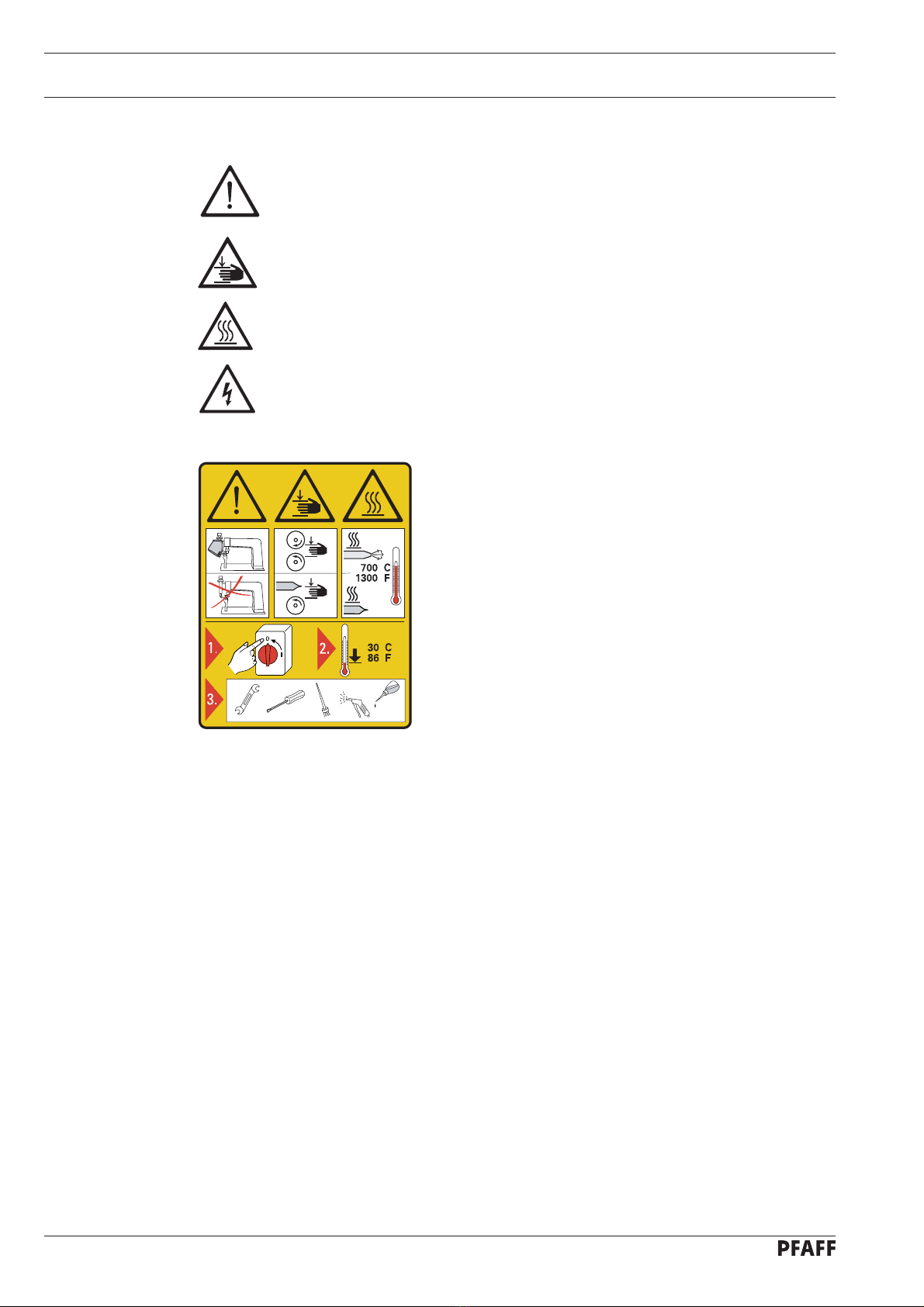
1.03 Safety symbols .......................................................................................................... 1 - 2
1.04 Important notes for the user ...................................................................................... 1 - 2
1.05 Operating and technical staff ..................................................................................... 1 - 3
1.05.01 Operating staff ...........................................................................................................1- 3
1.05.02 Technical staff ............................................................................................................ 1 - 3
1.06 Danger warnings ........................................................................................................ 1 - 4
2Proper use................................................................................................................. 2 - 1
3Specifications ........................................................................................................... 3 - 1
4Machine disposal ..................................................................................................... 4 - 1
5Transportation, packing and storage ...................................................................... 5 - 1
5.01 Transportation to customer’s premises ..................................................................... 5 - 1
5.02 Transportation inside customer’s premises ............................................................... 5 - 1
5.03 Disposal of packing materials ..................................................................................... 5 - 1
5.04 Storage ......................................................................................................................5 - 1
6Explanation of symbols ........................................................................................... 6 - 1
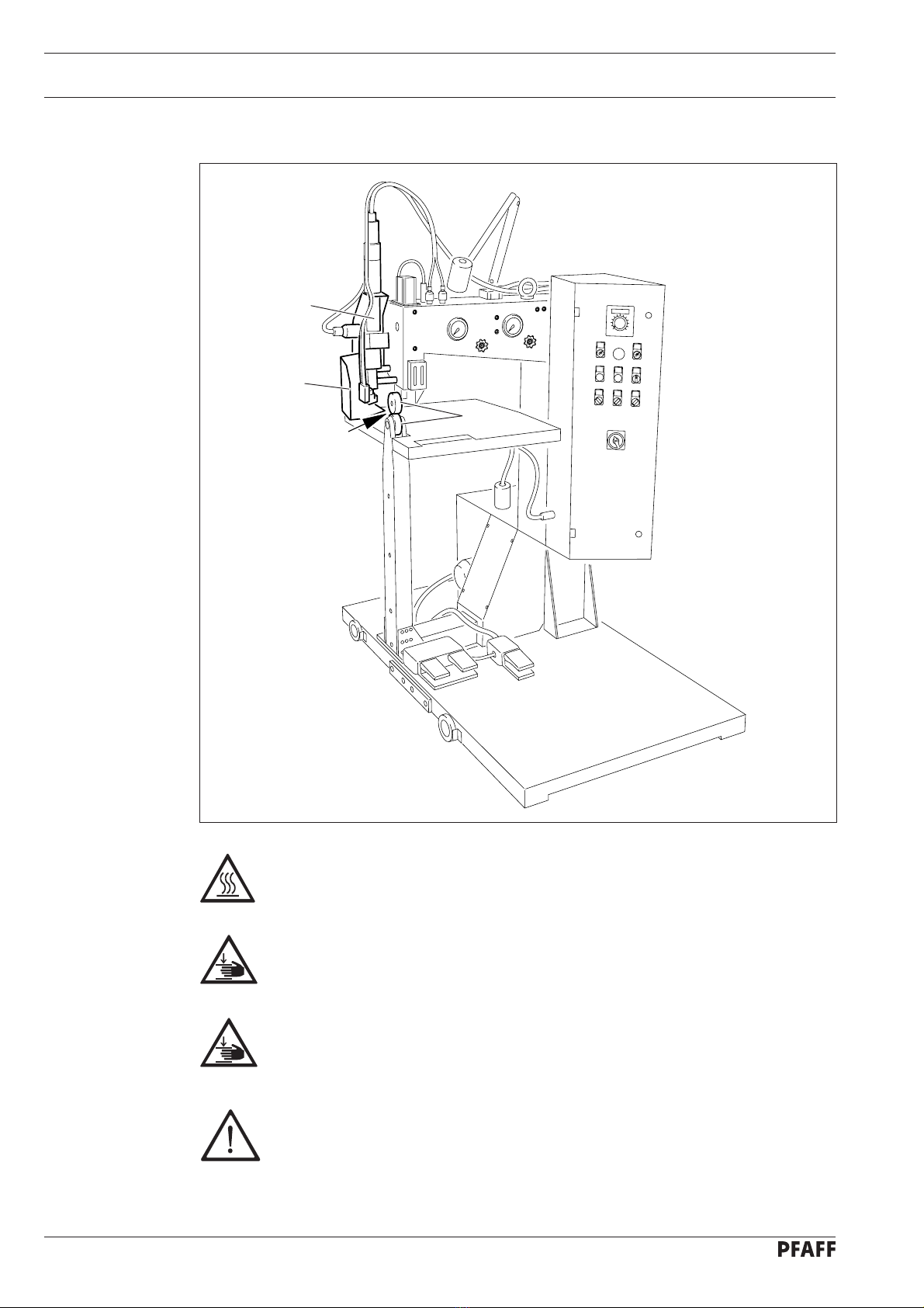
7Controls .................................................................................................................... 7 - 1
7.01 On-off switch ............................................................................................................. 7 - 1
7.02 Air valve ..................................................................................................................... 7 - 1
7.03 Foot switch for raising / lowering the feed rollers ...................................................... 7 - 2
7.04 Foot switch for starting the feed rollers ..................................................................... 7 - 2
7.05 Foot switch for engaging and disengaging the heating element ................................ 7 - 3
7.06 Knee switch / foot switch for mobile drive (only for the PFAFF 8309-026) ................. 7 - 3
7.07 Temperature regulator ............................................................................................... 7 - 4
7.08 Status display of temperature control ........................................................................ 7 - 4
7.09 Regulator for the heat-sealing speeds ........................................................................ 7 - 5
7.10 Reset switch / horn .................................................................................................... 7 - 5
7.11 Switch for heating capacity (only for machines with hot wedge) ............................... 7 - 6
7.12 Switch for the operating direction .............................................................................. 7 - 6
7.13 Switch for the mobile machine drive ( only for PFAFF 8309-026 ) .............................. 7 - 7
7.14 Switch for the automatic operation of the heating element ....................................... 7 - 7
7.15 Adjusting screw for limiting the penetration depth .................................................... 7 - 8
7.16 Regulator for the feed roller pressure and the hot air pressure .................................. 7 - 8
8Installation and commissioning .............................................................................. 8 - 1
8.01 Installation .................................................................................................................. 8 - 1
8.02 Commissioning .......................................................................................................... 8 - 2
8.03 Switching the machine on / off .................................................................................. 8 - 2
8.03.01 Switching machine with hot wedge on / off ............................................................... 8 - 2
8.03.02 Switching machine with hot-air nozzle on / off ........................................................... 8 - 3

Contents
Contents ............................................................................... Chapter - Page
9Setting up ................................................................................................................. 9 - 1
9.01 Adjusting the hot wedge (only for machines with hot wedge) ................................... 9 - 1
9.01.01 Lateral and angle positioning of the hot wedge .......................................................... 9 - 1
9.01.02 Setting the height of the hot wedge .......................................................................... 9 - 2
9.01.03 Clearance and pressure of the hot wedge on the feed rollers .................................... 9 - 3
9.02 Setting the hot-air nozzle (only for machines with hot-air nozzle) ............................... 9 - 4
9.02.01 Lateral and angle positioning of the hot-air nozzle ...................................................... 9 - 4
9.02.02 Setting the height of the hot-air nozzle ....................................................................... 9 - 5
9.02.03 Distance of the hot-air nozzle to the feed rollers ........................................................ 9 - 6
9.03 Setting the penetration depth .................................................................................... 9 - 7
9.04 Switching the automatic heating element on / off ...................................................... 9 - 7
9.05 Setting the heat-sealing temperature and speed ........................................................ 9 - 7
9.06 Setting the hot air pressure and heat-sealing pressure .............................................. 9 - 8
10 Heat sealing ............................................................................................................ 10 - 1
10.01 Heat-sealing principle ............................................................................................... 10 - 1
10.02 Heat-sealing procedure ............................................................................................ 10 - 2
10.02.01 Heat-sealing without automatic heating element ..................................................... 10 - 2
10.02.02 Heat-sealing with automatic heating element .......................................................... 10 - 2
11 Care and maintenance ........................................................................................... 11 - 1
11.01 Maintenance table ................................................................................................... 11 - 1
11.02 Cleaning ................................................................................................................... 11- 1
11.02.01 Machines with hot wedge........................................................................................ 11 - 1
11.02.02 Machines with hot air nozzle .................................................................................... 11 - 1
11.03 Checking / setting air pressure ................................................................................. 11 - 2
11.04 Emptying/cleaning water container of the air filter / regulator .................................. 11 - 2
11.05 Checking fuses ........................................................................................................ 11 - 3
11.06 Drive chains ............................................................................................................. 11 - 4
11.06.01 Tightening drive chains ............................................................................................ 11 - 4
11.06.02 Greasing drive chains ............................................................................................... 11 - 5
11.07 Cleaning filter for finest particles (only for machines with hot-air nozzle) ................. 11 - 5
11.08 Changing top feed roller ........................................................................................... 11 - 6
11.09 Changing bottom feed roller ..................................................................................... 11 - 6
11.10 Changing heating cartridge (only for machines with hot-air nozzle) .......................... 11 - 7
11.11 Changing temperature sensor .................................................................................. 11 - 8
11.12 Changing hot wedge (only for machines with hot wedge) ....................................... 11 - 9
11.13 Changing the hot-air nozzle (only for machines with hot-air nozzle) .......................... 11 - 9
11.14 Grinding in the hot wedge (only for machines with hot wedge) ............................... 11 - 10
11.15 Adjusting safety coupling (only for PFAFF 8309-026) ............................................... 11 - 11
11.16 Adjusting brake (only for PFAFF 8309-026) .............................................................. 11 - 11
12 Circuit diagrams ..................................................................................................... 12 - 1

Safety
1 - 1
1 Safety
1.01 Directives
This machine is constructed in accordance with the European regulations indicated in the
conformity and manufacturer’s declarations.
In addition to this instruction manual, please also observe all generally accepted, statutory
and other legal requirements, including those of the user’s country, and the applicable
pollution control regulations! The valid regulations of the regional social insurance society for
occupational accidents or other supervisory authorities are to be strictly adhered to!
1.02 General notes on safety
●The machine must only be operated by adequately trained operators and only when the
instruction manual has been fully read and understood!
●All notices on safety and the instruction manual of the motor manufacturer are to be read
before the machine is put into operation!
●All notes on the machine concerning danger and safety must be observed!
●The machine must be used for the purpose for which it is intended and must not be
operated without its safety devices; all regulations relevant to safety must be adhered to.
●When changing the feed rollers, the hot wedge or the hot-air nozzle, when the workplace
is left unattended and during maintenance or repair work, the machine must be switched
off at the mains and protective measures taken to prevent it being switched on again!
●Daily maintenance work must only be carried out by appropriately trained persons!
●Repairs and special maintenance work must only be carried out by qualified technical
staff or persons with appropriate training!
●During maintenance or repairs on the pneumatic system the machine must be
disconnected from the compressed air supply! The only exception to this is when
adjustments or function checks are carried out by appropriately trained technical staff!
●Work on the electrical equipment must only be carried out by technical staff who are
qualified to do so!
●Work on parts or equipment connected to the power supply is not permitted! The only
exceptions to this are specified in regulations EN 50110.
●Conversion or modification of the machine must only be carried out under observation of
all relevant safety regulations!
●Only spare parts which have been approved by us are to be used for repairs! We draw
special attention to the fact that spare parts and accessories not supplied by us have not
been subjected to testing nor approval by us. Fitting and/or use of any such parts may
cause negative changes to the design characteristics of the machine. We shall not
accept any liability for damage caused by the use of non-original parts.

Safety
1 - 2
1.03 Safety symbols
Danger!
Special points to observe.
Danger of hands being crushed!
Danger of burns from hot surface!
Danger from electric voltage!
1.04 Important notes for the user
●This instruction manual belongs to the equipment of the machine and must be available
to the operating staff at all times.
This instruction manual must be read before the machine is operated for the first time.
●Both operating and technical staff must be instructed on the safety devices of the
machine and on safe working methods.
●It is the duty of the user to operate the machine in perfect running order only.
●The user must ensure that none of the safety devices are removed nor put out of
working order.
●The user must ensure that only authorized persons operate and work on the machine.
●If the maximum limit for the emission of hazardous fumes is exceeded during processing
PVC, PTFE and similar materials, the user must have an efficient extraction system
installed.
For further information please refer to your PFAFF agency.
Caution
Do not operate without finger guard and safety devices.
Turn off the main switch and let the machine cool
down before any setting up, maintenance or cleaning
work!
o
o
o
o

Safety
1 - 3
1.05 Operating and technical staff
1.05.01 Operating staff
Operating staff are the persons responsible for setting up, operating and cleaning the
machine and for removing any disturbances in the sewing area.
The operating staff is obliged to observe the following points, and must:
●always observe the notes on safety in this instruction manual!
●avoid using any working methods which adversely affect the safety of the machine!
●avoid wearing loose-fitting clothing or jewelry such as necklaces or rings!
●also ensure that only authorized persons are allowed near the danger area of the
machine!
●immediately report to the user any changes to the machine that may affect its safety!
1.05.02 Technical staff
Technical staff are persons who have been trained in electrical engineering, electronics and
mechanical engineering. They are responsible for lubricating, servicing and repairing the
machine.
The technical staff is obliged to observe the following points, and must:
●always observe the notes on safety in this instruction manual!
●switch off the on/off switch before carrying out any maintenance and repair work on the
machine!
●never work on parts or equipment still connected to the power supply! Exceptions to this
are only permissible according to regulations EN 50110.
●replace all safety covers after maintenance and repair work!

Safety
1 - 4
Fig. 1 - 01
Do not operate the machine without protective cover 1!
Danger of burns if the hot-air nozzle or the hot wedge are touched!
Do not put your hand between protective cover 1and swivel unit (see arrow)!
Danger of crushing when the swivel unit 2is engaged or disengaged!
Do not touch moving feed rollers 3!
Danger of fingers being crushed!
For the PFAFF 8309-026 the space between the tracks must be even!
Provide barriers for persons in the track area!
Danger of crushing by the moving machine!
1.06 Danger warnings
1
2
3

Proper use
2 - 1
2 Proper use
The PFAFF 8309-023 is a stationary heat-sealing appliance with a self-drive mechanism for
the sealing process and is equipped with a hot-air nozzle or hot wedge.
The PFAFF 8309-026 is a mobile heat-sealing appliance with a self-drive mechanism for the
sealing process and is equipped with a hot-air nozzle or hot wedge.
Both machines are used for sealing technical textiles and sheets of suitable plastics (flexible
thermoplastics).
Any use of these machines which is not approved by the manufacturer shall be
considered as improper use! The manufacturer shall not be liable for any
damage arising out of improper use! Proper use shall also be considered to
include compliance with the operation, adjustment, service and repair measures
specified by the manufacturer!

Specifications
3 - 1
3 Specifications ▲
Length:
PFAFF 8309-023 ..................................................................................................... 900 mm
PFAFF 8309-026 ................................................................................................... 1510 mm
Width: .................................................................................................................. 1260 mm
Height: ................................................................................................................. 1600 mm
Weight:
PFAFF 8309-023 .................................................................................approximately 385 kg
PFAFF 8309-026 .................................................................................approximately 425 kg
Power consumption:
Machine with hot-air nozzle: ........................................................................... max. 3500 W
Machine with hot wedge: ............................................................................... max.1500 W
Heating capacity:
Machine with hot-air nozzle: ....................................................................... 1900 ( 3000 ) W
Machine with hot wedge: ............................................................................ 500 ( 1000 ) W
Mains fuse: ......................................................................................................... 16 A, inert
Power supply: ................................................................................................ 230 V / 50 Hz
Sealing temperature:
Machine with hot-air nozzle: ............................................................................. max. 610 °C
Machine with hot wedge: ................................................................................ max. 450 °C
Sealing speed: ............................................................................................. max. 10 m/min.
Pressure of sealing roller: .................................................................................. max. 500 N
Diameter of sealing roller: ..................................................................................... 65.1 mm
Seam width: ........................................................................................... 15, 20, 30, 40 mm
Hem width: ........................................................................................ 60, 80, 100, 120 mm
Clearance width (to edge of feed roller) .......................................... approximately 560 mm
Air consumption:
Machine with hot-air nozzle: ...............................................................approximately 250 l/h
Machine with hot wedge: ....................................................................approximately 40 l/h
▲ Subject to technical alterations

Disposal of machine
4 - 1
4 Disposal of machine
●Proper disposal of the machine is the responsibility of the customer.
●The materials used for the machine are steel, aluminium, brass and various plastic
materials.
The electrical equipment consists of plastic materials and copper.
●The machine is to be disposed of according to the locally valid pollution control
regulations.
Care must be taken that parts soiled with lubricants are disposed of separately
according to the locally valid pollution control regulations!

Transportation, packing and storage
5 - 1
5 Transportation, packing and storage
5.01 Transportation to the customer’s premises
Within the Federal Republic of Germany the machine is delivered without packing.
Machines intended for export are packed.
5.02 Transportation inside the customer’s premises
The manufacturer cannot be made liable for transportation inside the customer’s premises
nor to other operating locations.
Only for the PFAFF 8309-026
During transportation take care to avoid damage to the drive pinion!
Apply transit support, see Chapter 8.01 Installation.
5.03 Disposal of packing materials
The packing materials of these machines consist of paper, cardboard, VDE fibre and wood.
Proper disposal of the packing materials is the responsibility of the customer.
5.04 Storage
If the machine is not in use, it can be stored for up to 6 months. It should be protected
against dust and moisture.
If the machine is stored for longer periods, the individual parts, especially the surfaces of
moving parts, must be protected against corrosion, e.g. by a film of oil.

Explanation of symbols
6 - 1
6 Explanation of symbols
In this instruction manual, work to be carried out or important information is accentuated by
symbols. These symbols have the following meanings:
Note, information
Cleaning, care
Lubrication
Maintenance, repairs, adjustment, service work
(only to be carried out by technical staff)

Controls
7 - 1
7 Controls
7.01 On-off switch
●By turning the on/off 1switch the
machine is switched on or off.
Position 0: Machine is switched off
Position I: Machine is switched on
When switching the machine
off, please observe the notes in
Chapter 8.03 Switching the
machine on / off!
When the machine is switched
on, lamp 2lights up.
7.02 Air valve
●The compressed air supply is shut off or
opened by turning air valve 1.
Before shutting off the air
supply, please observe the
notes in Chapter 8.03
Switching the machine
on / off!
1
Fig. 7 - 02
zu
auf
Fig. 7 - 01
1
2

Controls
7 - 2
7.03 Foot switch for raising / lowering the feed rollers
●When the foot switch 1 is pressed down,
the top feed roller is raised until the foot
switch is released again.
Fig. 7 - 03
7.04 Foot switch for starting the feed rollers
●After pressing down the two-stage foot
switch 1, the feed rollers are started.
Stage 1: sealing speed 1
Stage 2: sealing speed 2
●The feed rollers remain in operation as
long as the foot switch 1is pressed
down.
Depending on the pre-setting,
the heating element is
automatically swung into
position when the feed rollers
are started. See Chapter 7.14
Switch for automatic
operation of the heating
element.
For setting the sealing speed,
see Chapter 7.09 Regulator
for sealing speed.
Fig. 7 - 04
1
1

Controls
7 - 3
7.06 Knee switch / foot switch for mobile drive (only for the PFAFF 8309-026)
●When the knee switch 1is operated,
the mobile machine unit stops, while
the feed rollers continue to move.
As an alternative to the knee
switch 1, the foot switch 2can
be delivered with the same
function (e.g. for machines
without a table).
7.05 Foot switch for engaging and disengaging the heating element
●The heating element can be engaged or
disengaged by pressing down foot
switch 1.
The function of the foot
switch 1is dependent on the
selected pre-setting, see
Chapter 7.14 Switch for
automatic operation of the
heating element.
Fig. 7 - 05
Fig. 7 - 06
1
1
2

Controls
7 - 4
2
Fig. 7 - 08
Fig. 7 - 07
7.08 Status display of temperature control
●Depending on the status of the
temperature control, diodes 1 - 6 light up.
Diode 1lights up when the actual
temperature deviates from the
required temperature by +/-50°C.
Diode 2lights up, if the temperature
exceeds 650°C, or if the sensor
breaks.
Diode 3- no function
Diode 4- no function
Diode 5lights up as soon as the heating is
switched on.
Diode 6lights up when the machine is
heated.
7.07 Temperature regulator
●The temperature can be set with the
buttons 1.
●Display 2shows the required value and
display 3the actual value.
1
3
2
1
3
4
5
6

Controls
7 - 5
7.09 Regulator for the heat-sealing speeds
●By turning regulator 1the first speed
level of the heat-sealing equipment is
set.
●By turning regulator 2 the second speed
level of the heat-sealing equipment is set.
The heat-sealing speeds can be
set as required within the range
0 - 10 m/min.
Fig. 7 - 09
Fig. 7 - 10
Fig. 7 - 09
Fig. 7 - 10
Fig. 7 - 09
1
2
12
7.10 Reset switch / horn
If one of the following malfunctions occurs,
the horn 1 sends out a signal and the lamp in
the reset button 2lights up:
- Malfunction of the temperature sensor
(e.g. sensor has broken)
- Over-heating of the hot wedge or of the
heating cartridge
- The difference between the selected and
the actual temperature is greater than
60°C (heat-welding temperature is not
reached)
When a malfunction occurs:
●correct the malfunction.
●quit the malfunction signal by pressing
the reset button 2(lamp goes off).

Controls
7 - 6
7.12 Switch for the operating direction
●By turning the switch 1, you can select
the direction of the feed rollers.
Switch 1lights up when set at
“reverse“.
7.11 Switch for heating capacity (only for machines with hot wedge)
●By turning the switch 1the heating
capacity can be set at three levels.
Level 0: Reduced heating capacity
in the entire working area
Level I: Standard operation
Reduced heating capacity when
the hot wedge is disengaged,
full heating capacity when the
hot wedge is engaged.
Level II: Speed-controlled heating
capacity
At the first heat-sealing speed
level, the heating capacity is
reduced. When the machine is
switched over to the second
speed level, the full heating
capacity is in operation.
Fig. 7 - 11
1
Fig. 7 - 12
1

Controls
7 - 7
7.13 Switch for the mobile machine drive ( only for PFAFF 8309-026 )
●By turning the switch 1, you can switch
the mobile machine drive on or off.
When the mobile machine
drive is switched on, switch 1
lights up.
Fig. 7 - 13
1
Fig. 7 - 14
1
7.14 Switch for the automatic operation of the heating element
●By turning switch 1, the automatic
operation of the heating element can be
switched on or off.
Position 0: Automatic operation off
The heating element is swung
into and out of position with the
use of the foot switch, see
Chapter 7.05 Foot switch for
engaging and disengaging
the heating element.
Position 1: Automatic operation on
The heating element is engaged
automatically when the feed
rollers start, and can be
disengaged at any time during
operation by operating the foot
switch, see Chapter 7.05 Foot
switch for engaging and
disengaging the heating
element.
This manual suits for next models
1
Table of contents
Other Pfaff Sewing Machine manuals

Pfaff
Pfaff Sewing Machine Guide

Pfaff
Pfaff 3822-1/22 User manual

Pfaff
Pfaff creative 3.0 User manual

Pfaff
Pfaff Creative 2134 User manual

Pfaff
Pfaff 2481-980/30 PLUSLINE Guide

Pfaff
Pfaff 141 User manual

Pfaff
Pfaff 294 User manual

Pfaff
Pfaff 3822-2/42 User manual

Pfaff
Pfaff 436 User manual

Pfaff
Pfaff 118 User manual

Pfaff
Pfaff tiptronic 6232 User manual

Pfaff
Pfaff 2481-3/01-980/30 User manual

Pfaff
Pfaff 1471 E1 User manual

Pfaff
Pfaff Series 580 Owner's manual

Pfaff
Pfaff HD SCREEN User manual

Pfaff
Pfaff expression line User manual

Pfaff
Pfaff 1163 Guide

Pfaff
Pfaff hobbylock 4762 User manual

Pfaff
Pfaff 3834-3/11 User manual

Pfaff
Pfaff 583 User manual