Mainca BC-1800 User manual

1
EQUIPAMIENTOS CARNICOS, S.L.
C.I.F. ES B-59553750
BC-1800
1 - ESPAñOL 1
2 - ENGLISH 9
3 - FRANÇAIS 16
4 - DEUTSCH 24
5 - PYCCKИЙ 32
P. I. “Coll de la Manya” - Jaume Ferràn, s/n. E-08400 Granollers (Barcelona) SPAIN
(+34) 93 849 18 22 / 17 54 – Fax: (+34) 93 849 71 76. www.mainca.com / E-mail: [email protected]om
Versión 31-03-2015

CORTADORAS DE CHULETAS
CONFEC. DE HAMBURGUESAS
EMBUTIDORAS AMASADORAS
CORTADORAS DE FILETAS
PICADORAS Y CUTTERS
MAQUINARIA INDUSTRIA CÁRNICA
EQUIPAMIENTOS CÁRNICOS, S.L.
N.I.F.ES B-59553750
Carretera Nacional 152 Km. 24.B
Polígono Industrial “COLL DE LA MANYA”
Jaume Ferrán, s/n. – Tels. 849 18 22 – 849 17 54
Fax: 849 71 76
08400 GRANOLLERS (Barcelona) SPAIN
IMPORTANTE
Al hacer los pedidos de recambios de material eléctricos, rogamos
indiquen la marca y referencia completa tomada del aparato.
IMPORTANT
Pour les comandes de matériel électrique, indiquez s´il vous plait, la
marque et la référence complète, prise de l´appareil.
IMPORTANT
When placing an order of any electric components, please advice us of
the reference number indicated in the parts to be exchanged and its trade
mark.
ACHTUNG
Für elektrische Bauersatzteil-Bestellungen, geben Sie uns bitte den
Lieferrantennamen und die genaue Referenznummer der zu
austauschenden Teile an.

CORTADORAS DE CHULETAS
CONFEC. DE HAMBURGUESAS
EMBUTIDORAS AMASADORAS
CORTADORAS DE FILETAS
PICADORAS Y CUTTERS
MAQUINARIA INDUSTRIA CÁRNICA
EQUIPAMIENTOS CÁRNICOS, S.L.
N.I.F.ES B-59553750
Carretera Nacional 152 Km. 24.B
Polígono Industrial “COLL DE LA MANYA”
Jaume Ferrán, s/n. – Tels. 849 18 22 – 849 17 54
Fax: 849 71 76
08400 GRANOLLERS (Barcelona) SPAIN
ATENCIÓN
La máquina debe conectarse a la red, obligatoriamente, a través de un
protector diferencial de calibre adecuado a las características técnicas
indicadas en la placa de la máquina.
WARNING
The machine must be connected to a power breaker ( combined
overload and earth leakage detector ) rated as per the details on the
machine data plate.
ATTENTION
La machine devra se brancher, obligatoirement, a la prise générale
moyennant un interrupteur de sécurité calibré selon les renseignements
techniques de la machine, les quelles sont détaillées sur la petite plaque
de caractéristiques.
ACHTUNG
Das Gerät muss an das Stromnetz geschaltet werden. Dabei ist
vorschriftsmässig ein Differenzial-Schutz zu verwenden, welcher nach
den auf dem Typenschild ausgewiesenen technischen Eigenschaften
arbeitet.

1
SIERRA CINTA BM
ÍNDICE
- INSTALACIÓN.
- DESCRIPCIÓN DE LA MÁQUINA.
- CONDICIONES DE UTILIZACIÓN.
- INSTRUCCIONES DE UTILIZACIÓN.
- CAMBIO DE CINTA.
- REGULACIÓN DE LA CINTA.
- LIMPIEZA.
- NIVEL SONORO.
- ESQUEMA ELÉCTRICO II.
- ESQUEMA ELÉCTRICO III
- LISTADO DE MATERIAL ELÉCTRICO.
- FIGURA 01
- FIGURA 02
- FIGURA 03
- LISTA DE RECAMBIOS.
INSTRUCIONES
Antes de cualquier manipulación de la máquina, deberán observarse todas las
indicaciones del Manual de Instrucciones.
El uso de la máquina con cualquier modificación de los elementos relativos a la
seguridad que incorpora, puede provocar accidentes y viola la Directiva Social
89/655/CEE. Equipamientos Cárnicos S.L no se hace responsable del uso de la
máquina en estas circunstancias.

2
INSTALACIÓN
La máquina viene desde fábrica en posición de trabajo ( vertical ). Conservar esta
posición incluso durante el desembalaje, instalación o almacenaje.
- Situar la máquina sobre una superficie fija y sólida en un emplazamiento
con un espacio mínimo de 1.5 m de longitud, 1m de anchura y 2.1 m de altura.
(Ver figura 1).
- Compruebe que la máquina asienta perfectamente. En caso contrario,
ajuste los tacos base (A). Obsérvese la posición de trabajo en las figuras 1 / 2 / 3.
- La altura de la mesa o superficie de corte debe quedar entre 800 y 1050
mm del suelo.
- Comprobar que la tensión y la frecuencia de la
red se corresponden con las indicadas en la placa de
características técnicas de la máquina, así como el tipo
de alimentación de la red y de la máquina (monofásica,
trifásica, con o sin neutro). La máquina debe conectarse
a la red, obligatoriamente, a través de un protector
diferencial de calibre adecuado a las características
técnicas indicadas en la placa de la máquina.
- Comprobar que la iluminación en la zona de
corte es como mínimo de 750 Lux.
El instalador deberá adecuar la conexión macho ( clavija )
de la máquina a la base portadora de la red de modo que
se correspondan perfectamente.
A continuación, abra la tapa frontal de la máquina y
compruebe visualmente que la cinta esté correctamente
colocada tanto en la rueda superior como en la inferior
(las puntas de los dientes de la cinta de carne deben llegar
a nivel de la llanta ). Ver fig. 5 y 7.
Cierre la tapa, conecte la clavija a la red y:
- pulse el botón verde de marcha
- e inmediatamente el rojo de paro,
con ello Vd. debe observar:
- a/ si el sentido de giro (desde la posición de trabajo)
es correcto (si es horario) o incorrecto (si es
antihorario), en cuyo caso debería invertirse una fase en
1
2
3
5 6 7

3
la clavija macho de la máquina para que girase a derechas.
- b/ compruebe que la cinta sigue rotando correctamente colocada en las ruedas.
A partir de este punto, la máquina se considera instalada para su uso.
DESCRIPCIÓN DE LA MÁQUINA.
Esta sierra cinta esta formada por un motor eléctrico, que transmite su potencia
mediante un volante motriz y otro conducido a la cinta de corte. Todo el conjunto
está sustentado por una bancada de acero inoxidable, con sus correspondientes
tapas fijas en la parte posterior y una tapa abatible en la anterior, la cual permite la
limpieza de la cinta de corte, de los dos volantes y de los rasquetes destinados a la
limpieza permanente de la cinta durante el corte. Dicha tapa incorpora un interruptor
de seguridad que corta la alimentación eléctrica del motor, evitando así el
funcionaminto accidental de la máquina mientras la tapa se encuentra abierta.
La máquina incorpora de serie un tensor automático, como los modelos BM-3000JV
y BC-2500, BC-2000.
En cuanto a protecciones de seguridad para evitar el contacto accidental del
operario con la cinta durante la operación de corte, la máquina dispone de dos
opciones:
a). Apretador basculante, formado por un semitubo rectangular montado
verticalmente en la parte anterior de la cinta en toda su altura de corte, con un eje
articulado por su parte superior y una maneta de manipulación por la inferior.
b). Media mesa desplazable, formada por una plataforma metálica, con la
correspondiente protección vertical en la zona anterior de la cinta, unida a una
guía que permite su desplazamiento longitudinal.
Para cualquiera de las dos versiones, la sierra está equipada con una placa tope
de gruesos regulable transversalmente, con la finalidad de garantizar la protección
de la mano del operario al recoger la loncha o chuleta obtenida del corte.
En el lateral izquierdo de la bancada se monta dos pulsadores, uno de paro o
emergencia y otro de marcha. El de color verde se utiliza para poner la máquina en
funcionamiento, mientras que el de color rojo y saliente está destinado al paro
normal y de emergencia.
Se puede disponer de un recipiente colocado debajo del volante motriz inferior, de
tal forma que la merma producida por la operación de corte quede recogida en su
interior. En el modelo BM-3000JV dicho recipiente está incluido.
Antes de operar con la maquina comprobar el funcionamiento del paro de seguridad
abriendo la tapa frontal.
CONDICIONES DE UTILIZACIÓN.
El uso de esta sierra cinta está destinado a la industria ligera. No puede utilizarse
para uso doméstico.
El usuario de la máquina debe recibir una formación específica de utilización y haber
leído del manual de instrucciones antes de usar la sierra-cinta.

4
La máquina sierra cinta en cuestión es apta para cortar carne fresca, hueso, o
congelado, dependiendo de que incorpore la correspondiente cinta de carne, hueso
o congelado.
También es válida su utilización con cinta de carne para cortar carne fresca con
hueso de cordero, cerdo y chuleta de ternera.
Para cualquier otra utilización, deberán abstenerse de utilizar la máquina o bien
consultarlo con el fabricante. Asimismo, solo podrá utilizarse la cortadora en el modo
descrito en este manual.
La duración de la cinta depende del género que corta, así como de la presión que se
ejerce sobre ella. De todas formas, puede establecerse a título orientativo una
duración de 1000 a 2000 Kg. de género cortado. En el caso de las cintas de carne,
puede Vd. aprovechar mejor la cinta, ya que después de un cierto tiempo de uso, la
puede sacar y girar al revés de modo que corte con la parte del filo que no había
usado.Las cintas para hueso y para congelado solo pueden usarse en la posición
indicada en la fig. 7.
Para poner en marcha la máquina, es imprescindible haber leído detenidamente
todas las instrucciones y seguir las indicaciones de instalación y de utilización. En
caso de precisar alguna aclaración no dude en contactar con su proveedor, o bien,
con Equipamientos Cárnicos, S.L. directamente.
La máquina no podrá utilizarse con la tapa abierta, ni sin apretador basculante o sin
la mesa desplazable y el protector cinta ( en función del modelo ).
INSTRUCCIONES DE UTILIZACIÓN.
Antes de poner la máquina en marcha es preciso controlar su correcta colocación
sobre la superficie fija y sólida en la que se encuentra, el correcto posicionamiento y
tensaje de la cinta en los volantes (Fig. 5), el cierre de la tapa bancada (B).
Siempre que la pieza lo permita, procure cortar primero la zona con carne y luego la
parte del hueso.
Al trabajar con cinta de huesos o congelados deberá apartar los dos rasquetes (E)
hacia el fondo de la máquina para que haya espacio suficiente como para que el
diente no los toque.
Al volver a colocar la cinta de carne, acerque los rasquetes hacia el diente
procurando que queden justo al final de la media luna que
forma el cliente. Esto es muy importante para dejar un
perfecto acabado y limpieza de corte.
No intente nunca variar la dirección del corte cuando esté a
medio cortar puesto que la cinta corre el riesgo de
pandearse* y podría llegar a romperse.
Asimismo al cortar hueso o congelado no retroceda en el
corte porque podría provocar que la cinta saltara de la rueda.
EN CASO DE NECESIDAD DE PARO URGENTE, PULSAR
EL BOTÓN ROJO (D).
En caso de precisar alguna aclaración no dude en contactar con su proveedor, o
bien, con Equipamientos Cárnicos, S.L. directamente.
4

5
La maquina BM-3000JV disopone de rampa de descarga, en caso de ser necesario
su uso, levantar la tapa (Z) acompañandola hasta superar los 90º y bloqueandola en
esta posición por medio de la balda (O).
* Aclaración del término pandear: cuando por efecto del uso, o por haber forzado la
presión de corte, una cinta se tuerce, decimos que se ha pandeado. Esto es
fácilmente observable. Si tomamos una cinta pandeada e intentamos unirla por el
centro con los dedos, al observarla lateralmente veremos que adopta forma de ocho
(figura 4).
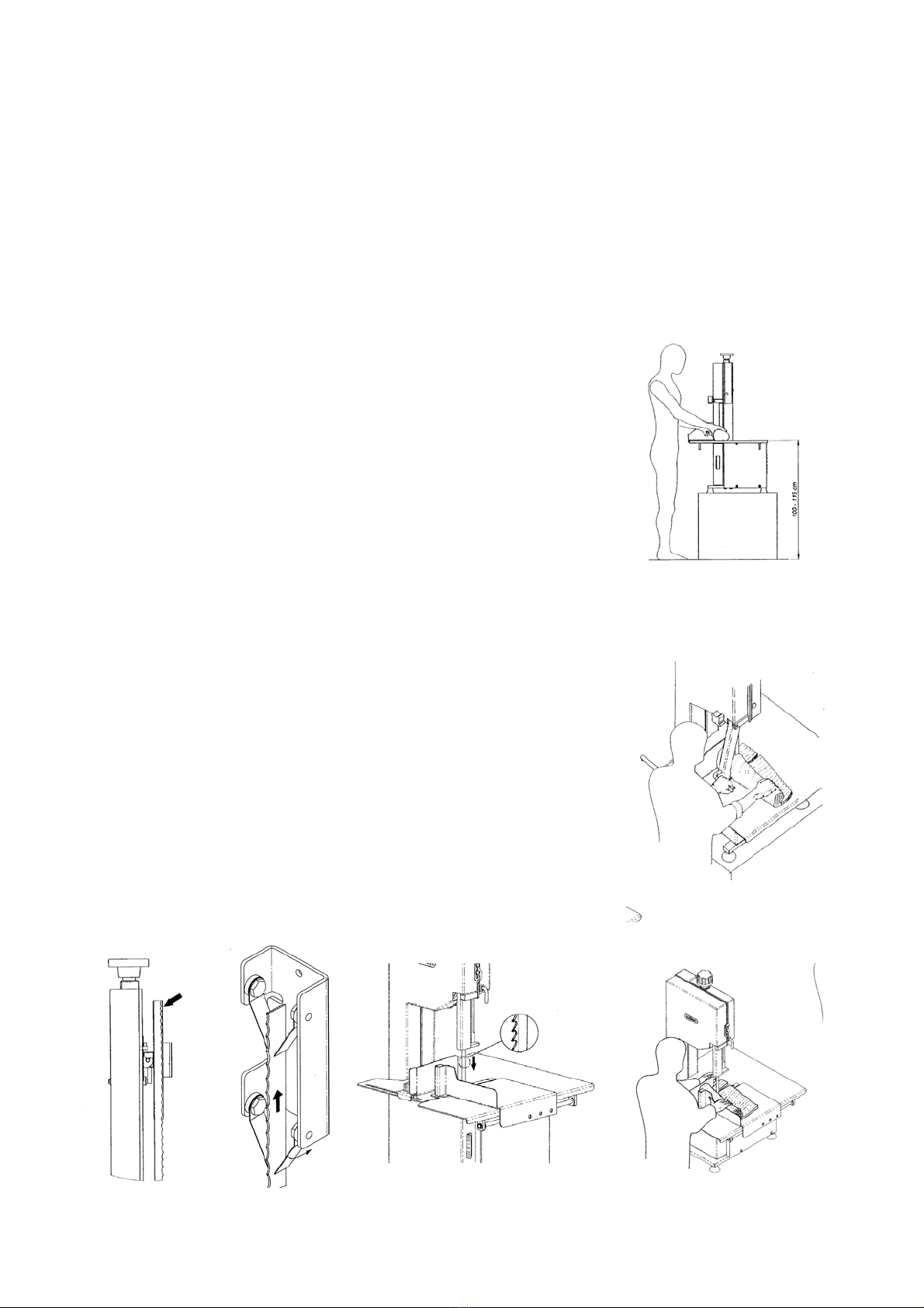
( MODELO CON MESA FIJA Y APRETADOR BASCULANTE ).
Antes de poner la máquina en marcha es preciso revisar el estado del apretador
basculante (C).
A continuación, desde la posición de trabajo, coloque con la mano derecha la pieza
a cortar entre la cinta y el apretador (C) que debe sostener por la maneta con la
mano izquierda.
A partir de este momento y con la mano derecha asiendo la pieza a cortar y la
izquierda en la maneta apretador, empiece a presionar ligeramente con una fuerza
uniforme sobre la maneta del apretador basculante, de este modo, la pieza a cortar
será oprimida contra la cinta, la cual cortará una loncha o chuleta (Fig. 2).
Solo cuando el apretador llega al final de su recorrido y queda en posición vertical,
puede retirar con la mano izquierda la pieza cortada.
Acto seguido coloque nuevamente la mano sobre la maneta apretador, desplácela
hacia usted para apartarla de la cinta, haga avanzar la pieza con la derecha hasta
lograr el nuevo grosor de corte, y empuje de nuevo con el apretador.
Para usar correctamente la sierra cinta al cortar carne con hueso, deberá actuar el
apretador de forma más rápida al cortar la carne y por contra disminuir la velocidad
al cortar el hueso. En caso contrario, forzaría el motor y la cinta se estropearía al
cabo de pocas operaciones.
( MODELO CON MESA DESPLAZABLE ).
Antes de poner la máquina en marcha es preciso revisar el estado de la media mesa
desplazable (F).
En primer lugar y con la máquina parada, coloque la pieza a cortar encima de la
media mesa desplazable (F) y ajuste el apoyo intermedio (G) convenientemente
(aproximadamente 10 mm por encima de la altura máxima de la pieza).
Acto seguido apoye firmemente la pieza contra la superficie vertical de la media
mesa desplazable y sujetelas como un solo bloque mediante su mano derecha
(desde la posición de trabajo) (fig. 3).
A continuación, poner en marcha la máquina y empujar todo el conjunto hacia la
cinta hasta notar que se llega al final de recorrido de la propia media mesa
desplazable. Una vez realizado el corte, apartar la loncha o chuleta con la mano
izquierda y hacer retroceder la media mesa hasta su tope anterior. Desplazar la
pieza hasta lograr el nuevo grosor de corte y repetir la operación descrita.
Puede utilizar la Placa tope para conseguir piezas del mismo grosor. Para ello debe
situar la Placa en la posición deseada y fijarla roscando el pomo.
Para usar correctamente la sierra cinta al cortar carne con hueso, deberá desplazar
la media mesa de forma más rápida al cortar la carne y por contra disminuir la
velocidad al cortar el hueso. En caso contrario, forzaría el motor y la cinta se
estropearía al cabo de pocas operaciones.

6
( MODELO BM-3000JV CON MESA DESPLAZABLE) TRABAJO CON MESA
DESPLAZABLE PLEGADA
Con la máquina parada verifique que el frontal de la mesa desplazable (F) está en su
posición inferior y está bloqueado por la balda (W), y el cuadrante mesa (U) se traba
en su posición superior, siendo totalmente plano la superficie del corte.
Revisar el estado del apretador basculante (C), deberá estar bloqueado por el
pasador de su soporte.
Acto seguido se deberá trabajar según descrito anteriormente en (INSTRUCCIONES
DE UTILIZACIÓN, MODELO CON MESA FIJA Y APRETADOR BASCULANTE)
( MODELO BM-3000JV CON MESA DESPLAZABLE) TRABAJO CON MESA
DESPLAZABLE DESPLEGADA
Para el corte con mesa desplazable deberá asegurarse primero de que esta se
encuentra liberada, en caso de no ser así, con la máquina parada se tirará del asa
del cuadrante mesa (U) hacia arriba y, manteniéndola ligeramente inclinada se
deslizará hacia atrás hasta hacer tope, en este punto se dejará pivotar hacia abajo
acompañándola hasta su posición vertical.
Para liberar la mesa desplazable (F) se desplazará la balda (W) hacia la izquierda y
se abatirla el frontal hacia su posición superior volviendo la misma balda a la
derecha para bloquear la posición en la mesa desplazable.
Para el uso de la mesa desplazable es obligatorio que el faldón quede en posición
vertical generando una pared a 90º con la superficie de la mesa.
También es necesario desmontar el apretador basculante (C), para ello abrir la tapa
frontal (B) tirando de las dos baldas (B·A) situadas en las partes superior e inferior
de la tapa junto a las asas, para desbloquear el apretador basculante se debe tirar
del clip que lo retiene hacia arriba y desplazar el apretador basculante hacia la
izquierda.
Acto seguido se deberá trabajar según descrito anteriormente en (INSTRUCCIONES
DE UTILIZACIÓN, MODELO CON MESA DESPLAZABLE)
CAMBIO DE CINTA
Para sacar la cinta, deberá desenroscar el tensor (H) (giro antihorario visto desde
encima de la máquina) con lo cual la cinta quedará floja y podrá sacarla de la
máquina.
Al volver a colocar la cinta procure que quede bien posicionada en la parte de los
rasquetes (E) (fig 6), rueda superior ( I )e inferior (J), plaquita central (K) y asegure
que pasa por la ranura del apoyo intermedio (L).
- Si su tensor es de tipo automático (04), deberá darle vueltas en el sentido horario
hasta que el dispositivo de tensión haga saltar el trinquete con lo cual habrá dado
la tensión correcta a la cinta.
- Si su tensor es manual proceda según el siguiente orden:
1º- Colocar la cinta según figura 1 (ver placa en máquina).
2º- Dar vueltas al tensor hasta que la cinta adopte la posición de la figura 2, pero
sin tensión.
3º- A continuación dar tres vueltas al pomo negro del tensor para que la cinta
adquiera la tensión correcta.

7
Después de cambiar la cinta deberá comprobar si es necesario hacer una regulación
según se describe a continuación.
REGULACIÓN DE LA CINTA
Para el buen funcionamiento de la máquina, se deberá comprobar el centraje de la
cinta en la rueda. Para ser correcto, la cinta deberá estar alineada con la llanta de la
rueda (ver figura 5).
De no ser así, se deberá corregir mediante la espiga graduación cinta (M), según se
describe a continuación:
Aflojar la tuerca (N) para desbloquear la espiga (M). Atornillándola, observaremos
como al hacer girar la rueda con la mano., la cinta se desplaza hacia atrás.
Por contra, si destornillamos, la cinta tendrá tendencia a venir hacia nosotros.
La operación de regulación del centraje de la cinta debe efectuarse atornillando y
destornillando mediante medias vueltas de la espiga (M) para que los
desplazamientos de cinta sean pequeños y no salga la cinta. Además, recuerde
hacer girar la rueda un par de vueltas, para observar el centrado de la cinta, después
de cada movimiento de la espiga (M).
Después de cambiar una cinta deberá comprobarse si su centrado es correcto, antes
de ponerla en funcionamiento.
LIMPIEZA
Para proceder a la limpieza de la sierra deberá desconectar la clavija de la red
eléctrica. Abra la tapa (B), afloje el tensor (H) y saque la cinta. Podrá sacar la rueda
conducida tirando de ella hacia arriba. Desenrosque la empuñadura rasquetes para
extraer el grupo rasquetes (O), en el modelo BM-3000JV deberá desmontar la rueda
conducida (I) quitando la tapa (T), que da acceso a la parte posterior del eje, con una
llave allen 8, deberá desenroscarlo en sentido horario (eje con rosca a izquierda).
Desmonte los rascadores cinta (E) tirando de los resortes de retencion y retire los
rascadores ruedas (X) tirando de ellos mientras presiona su muelle.
Para limpiar rascadoresy ruedas use un cepillo duro y agua caliente.
Con la ayuda de paños humedecidos con agua caliente y jabón neutro proceda a la
limpieza del interior de la tapa (B) y bancada (Y) así como del exterior junto con
mesa, tope, etc. Al final séquelo todo con un paño.
En la BM-3000JV, para vaciar y limpiar el cajetín merma retirelo hacia atrás desde
su parte inferior y levántelo hasta su posición horizontal dejando caer la merma, para
su limpieza use paños humedecidos con agua caliente y jabón neutro.
Preste especial atención a los residuos que pudiesen acumularse en las esquinas,
superficie ruedas, ranuras de rodaje de la cinta, rasquete inferior y parte trasera del
cubre rodamientos.
Para sacar la rueda inferior deberá extraer el tornillo (P). Para aflojar, deberán girar
la llave en sentido horario ya que se trata de tornillos con rosca a izquierda. Preste
especial atención a las juntas montadas entre tuerca (P) y rueda (J).
Evite el goteo de agua en la zona del tensor.

8
MANTENIMIENTO
Cada 200 horas de funcionamiento, es aconsejable engrasar con grasa alimentaria
las guías (Q) del tirante. Asimismo, saque el tensor y engrase el muelle y la rosca
del tensor.
Tambien debe verificarse periódicamente el correcto funcionamiento de parada de la
máquina en caso de apertura de la Tapa bancada.
Aconsejamos un cambio de rodamientos (R) al cabo de 10.000 horas de trabajo.
NIVEL SONORO
El nivel de presión acústica continuo equivalente ponderado " A " en el puesto de
trabajo y sin carga es de como máximo 74,5 dB( A ). Es recomendable el uso de
cascos de protección auditiva.

9
BANDSAW BM
INDEX
- INSTALLATION
- DESCRIPTION OF MACHINE
- CONDITIONS OF USE
- USER INSTRUCTIONS
- CHANGING THE SAW BLADE
- ADJUSTING THE SAW BLADE
- CLEANING
- SOUND LEVEL
- WIRING DIAGRAM. II
- WIRING DIAGRAM III
- ELECTRIC COMPONENTS
- FIGURE 01
- FIGURE 02
- FIGURE 03
- LIST OF SPARE PARTS
INSTRUCTIONS
Before any operation of the machine, the operator must observe all instructions
contained within this manual.
The use of this machine with any of the safety devices removed or modified, can
cause serious injury and violates Social Directive 89/655 EWG. EQUIPAMIENTOS
CARNICOS S.L does not accept responsibility for the operation of the machine under
those circumstances.

10
INSTALLATION
The machine arrives from the factory in a ready to use position (vertical). Conserve
this position during the unpacking and installation.
An area approximately 1,5m long x 1m wide x 2.1m high is required. See figure 1
Situate a machine over a level and strong surface following the instructions on Fig. 1.
Ensure that the machine is properly seated, if not; adjust the rubber feet to suit (A).
Observe the working position in figures 1 / 2 / 3.
Check that voltage and frequency are the same as shown on the machine
nameplate, as well as whether it is single or three-phase, with
or without neutral.
The installer must ensure the plug is adequately fitted to the
main supply to cope with the conditions existing in the work
area.
The machine must be wired to an earth leakage circuit breaker
of the appropriate rating.
Ensure the lighting of the cutting area above 750 Lux.
Open the door of the machine and visually check the band saw
is properly fitted on both the bottom and top pulley. The teeth of
the blade should be level with the edge of the pulley. See Fig.
5.
Shut the door, plug the machine to the mains and:
- press the green start button
- and immediately the red stop button.
In this way you should observe:
-a. If it is rotating correctly, that is clockwise when facing the
machine. On three phase machines, reserve a phase if it is
rotating anti-clockwise.
-b. Make sure the band is running correctly on the pulleys
From this point onwards the machine is considered ready for
use.
5 6 7
1
2
3

11
DESCRIPTION OF MACHINE
The bandsaw consists of an electric motor, driving a drive pulley, which connects via,
to the top pulley through the blade. A stainless steel frame supports the whole
assembly, with fixed covers at the back and a hinged removable door at the front for
ease of access for cleaning. This door incorporates a safety device, which cuts the
power, if the door is opened accidentally.
The standard configuration of the models BC-2500, BM-3000JV and BC2000
contains an automatic tightener.
Please check the function of safety switches before putting into operation.
For the operators protection the machine incorporates the following devices.
a) Hinged meat pusher, this is a metal U piece hinged at the top of the exposed
blade area with a pusher knob at the bottom of the U shaped guard.
b) Half-sliding table comprises a metal platform with a raised vertical component that
covers the lower exposed part of the blade, connected to a guide bar to facilitate
lateral movement.
On both versions the bandsaw is supplied with an adjustable slice thickness stop
plate that moves transversally to the direction of cut.
Two buttons are situated on the left of the bedplate: the green button is the on switch
and the red button is the off and emergency switch..
A waste product tray is available to collect waste from the bottom pulley, included in
BM-3000JV.
Before using machine, check the operation of emergency stop button.
CONDITIONS OF USE
This machine must not be applied for domestical use.
The user of the machine must receive a specific formation of use and read the
manual before use the band saw.
The band saw is designed to cut fresh meat, bone and frozen meat as long as the
correct band for, meat, bone or frozen meat is fitted. It is also acceptable to cut fresh
meat with a bone blade, if it is lamb, pork or veal.
For other cutting applications we do not recommend its use without prior consultation
with the manufacturer. Likewise, the machine must be used as described in the
instructions contained in this manual.
The longevity of the band depends on what is being cut and to the amount of
pressure exerted on it. Nevertheless, as guide one should expect it to last between
1000 and 2000 Kg of cut product. In the case of meat saws, you can obtain a longer
life because you can reverse the band and benefit by using the other side of the
tooth.

12
To switch the machine on, it is essential to have read the instructions and follow them
step by step. If in any doubt contact your local dealer or Equipamientos Carnicos SL
directly. The machine cannot be operated with the door open or without the follow
through guard in case of being the model with fixed table or, for the model with
folding moving table, will be obligatory the use of the follow through guard while the
table is folded and the use of the moving table with front protector in superior position
and blade protector regulated to the suitable height.
To use the machine, it is essential to have read at all the instructions and to follow
the indications of installation and use. In case of needing some explanation please,
not doubt in contacting with its supplier, or, with Equipamientos Cárnicos, S.L.
directly.
The machine will never be used with moving table folded and/or follow through guard
disassembled, depending on model.
INSTRUCTIONS FOR USE.
Before working on machine ensure it is placed on a sound level surface at the correct
working height. Check the alignment and tension of the blade (Fig. 5). The door is
locked (B).
When slicing meat with bone one should take care by exerting greater pressure when
slicing meat as against bone, in order to protect the band and avoid excessive strain
on the motor.
Never try to alter the direction of the cut once you are cutting as you run the risk of
snapping the blade and cause it to whip.
Likewise, when cutting bone or frozen meat, do not attempt to reverse your action as
you may slip the band from its pulley.
Whenever possible, try to position the product so that the meat side is cut before the
bone.
When working with bone or frozen meat blades, ensure the
scrapers (E) are forced backwards so that the blade teeth do
not touch.
When refitting the meat band, position the scrapers again close
to the teeth, so that it nears the tip. This is very important to
leave a clean and perfect cut.
IN CASE OF EMERGENCY, PRESS THE RED STOP
BUTTON (D)
In case of any doubts contact the manufacturer Equipamientos
Carnicos SL.
Important observation:
After long use or because the saw blade has been forced, the band may develop a
twist. This is clearly visible, simply hold the band at its middle and observe that it
does not look straight, but rather it has developed a twist like in figure 4.
In BM-3000JV, if necessary the machine has an unloading ramp, to its use must rise
to the cover (Z) up to 90º
4

13
( WITH FIXED TABLE AND HINGED PUSHER ).
First check the condition of the hinged pusher (C).
Place the product to between the blade and the adjustable portioner (C). From the
working position and with your right hand place the product between the blade and
the pusher held by handle with the left hand. From there on, with the right hand
holding the piece to be cut and the left hand the pusher, start to exert steady
pressure on the pusher which will force the blade onto the product, resulting in a
sliced portion. (Fig. 2)
Only when the pusher reaches the end of its travel and remains in a vertical position,
can you remove the sliced product with your left hand. Once again, place your hand
on the pusher and lift it towards you, allowing the operation to move the main product
sideways to the stop, in preparation of the next slice.
( MOVING TABLE ).
First check working of the sliding table (F).
With the machine switched off, place the piece to be cut on the table (F) and adjust
the intermediate slot guide (G) to be 10mm above the high of the cut piece.
Next,press firmly the product held in your right hand against the vertical surface of
the moving table (fig.3). Switch the saw on and push the assembly forward to the end
of its travel. Thereon, remove the sawn piece with your left hand and return the table
to the forward position.
When slicing meat with bone you should take care by exerting greater pressure when
slicing meat as against bone, in order to protect the band and avoid excessive strain
on the motor.
( BM-3000JV MODEL WITH FOLDING MOVING TABLE ) WORKING WITH
MOVING TABLE FOLDED
With the machine stopped verify that the front of the sliding table (F) is in its inferior
position and blocked by the lock (W) of fixation, and the table quadrant (U) is locked
in its superior position, being totally flat the cutting surface.
Check the condition of the hinged pusher (C).
After table is folded, follow steps described on ( INSTRUCTIONS FOR USE, WITH
FIXED TABLE AND HINGED PUSHER ).
( BM-3000JV MODEL WITH FOLDING MOVING TABLE ) WORKING WITH
MOVING TABLE
For the cut with sliding table make sure first that this is released, otherwise, with
stopped machine it will be thrown of the handle of the table quadrant (U) upwards
and, maintaining it slightly inclined one will slide backwards until making end, then it
will let pivot downwards following until its vertical position.
In order to release the sliding table (Z) turnright the locker (W) and turn the front
protector to its superior position, fix with same pin in hole of sliding table (F).
For the use of the sliding table it is obligatory that the front protector is vertical
making a wall to 90º with the surface of the table.

14
Also is necessary to disassemble the hinged pusher (C), open the front cover (B)
throwing of the two bolts (B·A) located in the parts superior and inferior of the cover
next to the handles, release the lock that retain it and move it towards the left.
After table is folded, follow steps described above, on ( INSTRUCTIONS FOR USE,
MOVING TABLE ).
CHANGING THE SAW BLADE
To remove the band it is necessary to unscrew tensioner (H) (Anti-clockwise when
looking from above the machine), which will loosen the blade and allow its removal.
When refitting the blade, ensure that it is well positioned with the scrapers (E) (figure
6), top pulley (I) and lower pulley (J), central plate (K) and that it passes through the
intermediate slot guide (L). If the tensioner is the automatic version (04), turn the
knob clockwise till the ratchet slips, indicating the band is correctly tensioned.
After replacing the band, one should check if any further adjustments are required as
follows:
ADJUSTING THE BLADE
To ensure that the machine is running properly, one must check that the band is
running true on the pulleys. To be correct, the band has to rest with the rim of the
blade aligned with the front end of the pulley. See Figure 5.
If it is not aligned, proceed to correct the alignment, by adjusting the inclination
assembly knob (M) as follows.
Unscrew the cap (S) to accede to the knob (M). Loosen the nut by means of lever (N)
to free the inclination knob (M). You will observe that by screwing the knob when at
the same time turning the band by hand, the blade will move backwards. Similarly,
when we unscrew it, the blade moves forward. The centring operation must be
carried out by screwing and unscrewing the knob so that the deviation of the band is
minimal and does not drop off (M). Remember to turn the pulley by hand each time
you adjust the inclination knob (M).
After replacing a band, you must ensure the blade is running true, before you run the
machine.
CLEANING
To proceed with cleaning the band saw, disconnect the plug from the mains. Open
the door (B), loosen the tensioner (H) and remove the band. Unscrew the scraper
securing knob, remove the scrapers (O) and the upper pulley pulling it up. For BM-
3000JV to disassemble to the upper pulley ( I ), unscrew the cover (T), that access to
the rear part of the axis, with allen key 8, unscrew it in clockwise. Disassemble the
scrapers (E) throwing of the retention rings and retire the scrapers wheels (X)
throwing of them while it presses its spring.
To clean scrapeprs and wheels, use a stiff brush and hot water.
With a damp cloth, hot water and a neutral detergent, clean the inside of the door
and body, as well as the exterior, together with the blade and guards, etc. Finally, dry
it off with a cloth.

15
In BM-3000JV, to empty and clean waste product tray move it backwards and pull it
up from its inferior part to its horizontal position dropping the waste, cleaning it with a
damp cloth, hot water and a neutral detergent and finally, dry it off with a cloth.
Pay special attention to residues that can accumulate on the corners, pulleys, pulley
grooves, lower scrapers and the back bearing covers.
To remove the lower pulley you must extract bolt (P). To loosen, unscrew clockwise
as these are left handed threads, pay attention to o-rings placed between pulley (J)
and bolt (P)
Avoid dripping water onto the electrical zone.
MAINTENANCE
After 200 hours of work, it is advisable to grease with edible grease the guides (Q) of
the tensioner, removing the cap (S) and the rear top cover (T). Likewise, remove the
tensioner; grease the spring (V) and the thread of the tensioner. We recommend
changing the bearing (R) after 10.000 hours of use.
SOUND LEVEL
The sound level in the work place is as maximum 74-dB (A). Ear defenders are
recommended when operating the machine.

16
SCIE A RUBAN BM
TABLE DES MATIERES
- INSTALLATION.
- DESCRIPTION DE MACHINE
- CONDITIONS D'UTILISATION.
- INSTRUCTIONS D’UTILISATION
- CHANGEMENT DE RUBAN.
- REGLAGE DU RUBAN.
- NETTOYAGE.
- ENTRETIEN
- NIVEAU SONORE.
- SCHEMA ELECTRIQUE.
- LISTE DU MATERIEL ELECTRIQUE.
- FIGURE 1.
- FIGURE 2.
- FIGURE 3.
- FIGURE 4.
- FIGURE 5.
- FIGURE 6.
- LISTE DES PIECES DE RECHANGE.
NOTICE D'EMPLOI.
Toutes les indications de la Notice d'Emploi devront être scrupuleusement observées
avant toute manipulation de la machine.
L'utilisation d'une machine sur laquelle aurait été effectuée une quelconque
modification des éléments de sécurité l'équipant peut provoquer des accidents et
enfreint la Directive Sociale 89/655/CEE.
Equipamientos Cárnicos S.L. n'est pas responsable de l'utilisation de la machine
dans ces conditions.

17
INSTALLATION.
La machine est livrée en position de travail (verticale). Maintenir cette position, même
lors du déballage et de l'installation.
- Placer la machine sur une surface fixe et solide, dans un espace minime de
1.5 m de longueur, 1 mettre de largeur et 2,1 m d’hauteur, en respectant les cotes
indiquées sur la figure 1.
- S'assurer que la machine est bien stable. Dans le cas contraire, régler les
chevilles de la base (A). Respecter la position de travail des figures 1, 2 et 3.
L’hauteur de la table ou surface de coupure doit rester
entre 800 et 1050 mm du sol.
- Vérifier que la tension et la fréquence du réseau
correspondent à celles indiquées sur la plaque des
caractéristiques techniques de la machine, ainsi que les
types d'alimentation du réseau et de la machine
(monophasé, triphasé, avec ou sans neutre).
- La machine doit se brancher au réseau obligatoirement
à travers d’un protecteur différentiel de calibre approprié
aux caractéristiques techniques indiquées sur la plaque de
la machine.
- Vérifier que l’illumination sur la zone de coupure est
d’un minime de 750 lux.
L'installateur devra adapter la connexion mâle (fiche) de la
machine au socle porteur du réseau, de façon qu'ils s’
assemblent parfaitement.
Ouvrir ensuite le couvercle frontal de la machine et vérifier
visuellement que le ruban est bien placé et bien tendue, tant
dans la roue supérieure comme dans la roue inférieure (les
pointes des dents du ruban à viande doivent arriver au niveau
de la jante). Voir fig. 5 et 7.
Fermer le couvercle, brancher la fiche au réseau et :
- enfoncer le bouton vert de mise en marche
- et immédiatement le bouton rouge d'arrêt,
ceci permet d'observer:
1
2
3
5 6 7
This manual suits for next models
4
Table of contents
Languages:
Other Mainca Saw manuals