manuals.online logo
Brands
  1. Home
  2. •
  3. Brands
  4. •
  5. Mainpine
  6. •
  7. Recording Equipment
  8. •
  9. Mainpine IQ Express RF6118 User manual

Mainpine IQ Express RF6118 User manual

Quick Start Guide for
Mainpine IQ Express™
Products
Part Nos. RF6118, RF6120, RF6122, RF6124
QS2021 © 2021 Mainpine, Inc. Issued: October 2021
Software installation
Driver Installation
Mainpine, Inc.
PO Box 241
Wilsonville
Oregon 97070-0241 USA
Tel. +1 866 363 6680
Outside
US +1 360 462 6292
Fax. +1 360 462 8160
Email. info@mainpine.com
Web: www.mainpine.com
You may be presented with a “Found New
Hardware” dialogue.
• From the command prompt enter “lspci” and
note the slot identification tag associated
with the installed “MainPine Ltd PCI Express
UART” device. (For example, 06:01.0)
• From the command prompt enter “dmesg |
grep 06:01.0” using the noted slot
identification tag instead of the example. The
output should show one ttyS device per
modem port. If it does, then no further
installation work is necessary.
Questions? Please visit:
http://www.mainpine.com
For users of Windows XP through 10
and Server 2003 through 2019: For users of Linux operating systems:
fax. simplified.
fax. simplified.
fax. simplified.
After installing the IQ Express board, restore system power. During the initial “power on self test”
the motherboard BIOS may display a list of installed devices with the IQ Express identified as a
“simple communications” controller or “PCI modem”. Wait until the operating system has completed
booting and then log on as a superuser with administrator rights (i.e. “Administrator” on Windows or
“root” on Linux).
• Using your web browser download the “Rev4”
IQ Express drivers from:
• Extract the downloaded zip file containing the
drivers.
• Direct the “Found New Hardware” dialogue (if
initiated) to the “32-bit” or “64-bit” folder, as
appropriate, in the location where the
downloaded zip file was extracted.
• Right-click on the “iqinstall.exe” file in the
extracted driver folder, and choose “Run as
Administrator”.
http://downloads.mainpine.com
Username: customer
Password: iqexpress
• If the output shows some, but not all modem
ports, then add “8250.nr_uarts=16” (where
“16” is at least two more than the number of
modems in the system) to the kernel options
(follow the instructions for your distribution
on how to do this) and reboot the system.
• If the output does not show any modem ports
then update to Linux kernel 2.6.28 or newer
and reboot.
Mainpine IQ Express™ 1-Port SP/LP
Mainpine IQ Express™ 2-Port SP/LP
Mainpine IQ Express™ 4-Port SP/LP
Mainpine IQ Express™ 8-Port SP/LP
Using this guide Hardware installation
CAUTION
Static sensitive device! Risk of electric shock
!
This guide applies to the
following Mainpine products:
This guide should be used in conjunction with documentation
found on the Mainpine website, http://www.mainpine.com.
Before you begin
• Read this guide thoroughly. Refer to the Regulatory Notice
document that contains important safety warnings and national
or international requirements for proper installation of this
product. This document can be found on the Mainpine website,
http://www.mainpine.com/REGNOT.PDF
• Familiarize yourself with instructions in the user manual, and
installation procedures from your PC documentation.
• Prepare your work area, and make sure you have the
appropriate tools, referring to your PC documentation prior to
removing the board from its packaging.
Package contents
1 x Quickstart Guide
1 x Low Profile Bracket
and either:
IQ Express™ 1-Port SP
1 x RJ11-RJ11 cable, or
IQ Express™ 2-Port SP
2 x RJ11-RJ11 cables, or
IQ Express™ 4-Port SP
2 x RJ14-RJ11 ‘Y’ cables, or
IQ Express™ 8-Port SP
2 x RJ61-RJ11 ‘Y’ cables
Physical description
The IQ Express boards are
multiport analog interface
boards for use inside PC
equipment in Fax applications.
The board will fit into any free
PCI Express x1, x4, x8, or x16
slot, and is fully compatible
with the short, long, low-
profile, and standard-profile
form factors
Computer components
are sensitive to
electrostatic discharges.
Make sure you follow
appropriate precautions
when handling this
board.
Always make sure
equipment is powered
down and disconnected
before attempting
installation of this
product or otherwise
opening covers.
1. Refer to your system documentation for information on removing covers and installing boards
throughout the procedure.
2. Make sure the system is switched off and all cables are safely disconnected. Make a note of
where cables are connected for reconnection later.
3. Remove the system cover.
4. Select any available PCI Express slot, remove the slot cover, and keep the screw for step 8.
5. Carefully remove the IQ Express™ board from the packaging, ensuring antistatic procedures
are observed. Hold the board only by the edges or mounting bracket, being careful to avoid
touching the PCI Express connector.
6. Keeping the board aligned with the PCI Express slot, gently and firmly insert the PCI Express
connector on the board into the PCI Express expansion slot in your system.
7. Ensure that the mounting bracket is flush with the chassis and that the PCI Express connector
is fully inserted and level.
8. Fasten the mounting bracket to the chassis.
9. Replace the system cover and reconnect all cables.
10. Connect the provided cables between the connectors on the board and the telephone sockets.
If longer cables are required it is recommended that RJ11 couplers be used in conjunction with
RJ11 extension cables to each telephone socket.
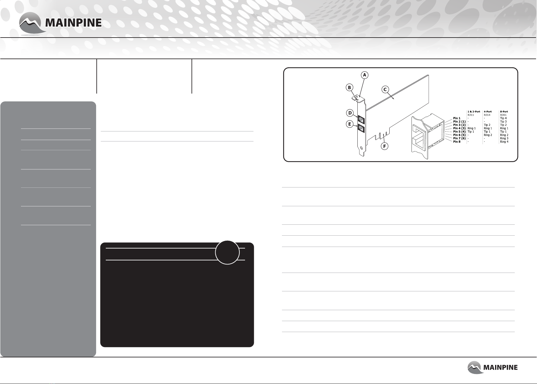
IQ Express™ fitted with
Standard Profile Bracket
Connector pinout
A. Mounting bracket
B. Mounting bracket
screw point
C. Base board
D. Connector for cable
to telephone sockets.
Ports 1,3,5,7
E. Connector for cable
to telephone sockets.
Ports 2,4,6,8
F. PCI Express connector
fax. simplified.
P/N: RF6118
P/N: RF6120
P/N: RF6122
P/N: RF6124

This manual suits for next models

3

Popular Recording Equipment manuals by other brands

Alesis IO MIX user guide

Alesis

Alesis IO MIX user guide

Honeywell Series A user guide

Honeywell

Honeywell Series A user guide

DAPAudio CDR-110 instruction manual

DAPAudio

DAPAudio CDR-110 instruction manual

Behringer Tweakalizer DFX69 user manual

Behringer

Behringer Tweakalizer DFX69 user manual

BLACK NOISE PIPE user manual

BLACK NOISE

BLACK NOISE PIPE user manual

YOKOGAWA ScopeCorder DL350 user manual

YOKOGAWA

YOKOGAWA ScopeCorder DL350 user manual

Waves DiGiGrid IOC user guide

Waves

Waves DiGiGrid IOC user guide

Roli Seaboard RISE 25 quick start guide

Roli

Roli Seaboard RISE 25 quick start guide

Lode Schiller CS200 Service documentation

Lode

Lode Schiller CS200 Service documentation

auray iso-armor owner's manual

auray

auray iso-armor owner's manual

Altera Arria 10 Avalon-ST Interface user guide

Altera

Altera Arria 10 Avalon-ST Interface user guide

AuviTran AxC-DS32IO instruction manual

AuviTran

AuviTran AxC-DS32IO instruction manual

BSS Audio TCS-804 Technical specification

BSS Audio

BSS Audio TCS-804 Technical specification

GRASS VALLEY T user manual

GRASS VALLEY

GRASS VALLEY T user manual

SMC Networks EX180-SDN4 Series Installation & maintenance manual

SMC Networks

SMC Networks EX180-SDN4 Series Installation & maintenance manual

Roland MKS-50 owner's manual

Roland

Roland MKS-50 owner's manual

Roland MSQ-700 owner's manual

Roland

Roland MSQ-700 owner's manual

PCCM MA-110 manual

PCCM

PCCM MA-110 manual

manuals.online logo
manuals.online logoBrands
  • About & Mission
  • Contact us
  • Privacy Policy
  • Terms and Conditions

Copyright 2025 Manuals.Online. All Rights Reserved.