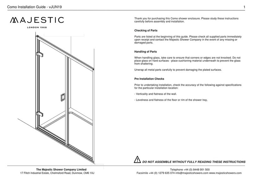
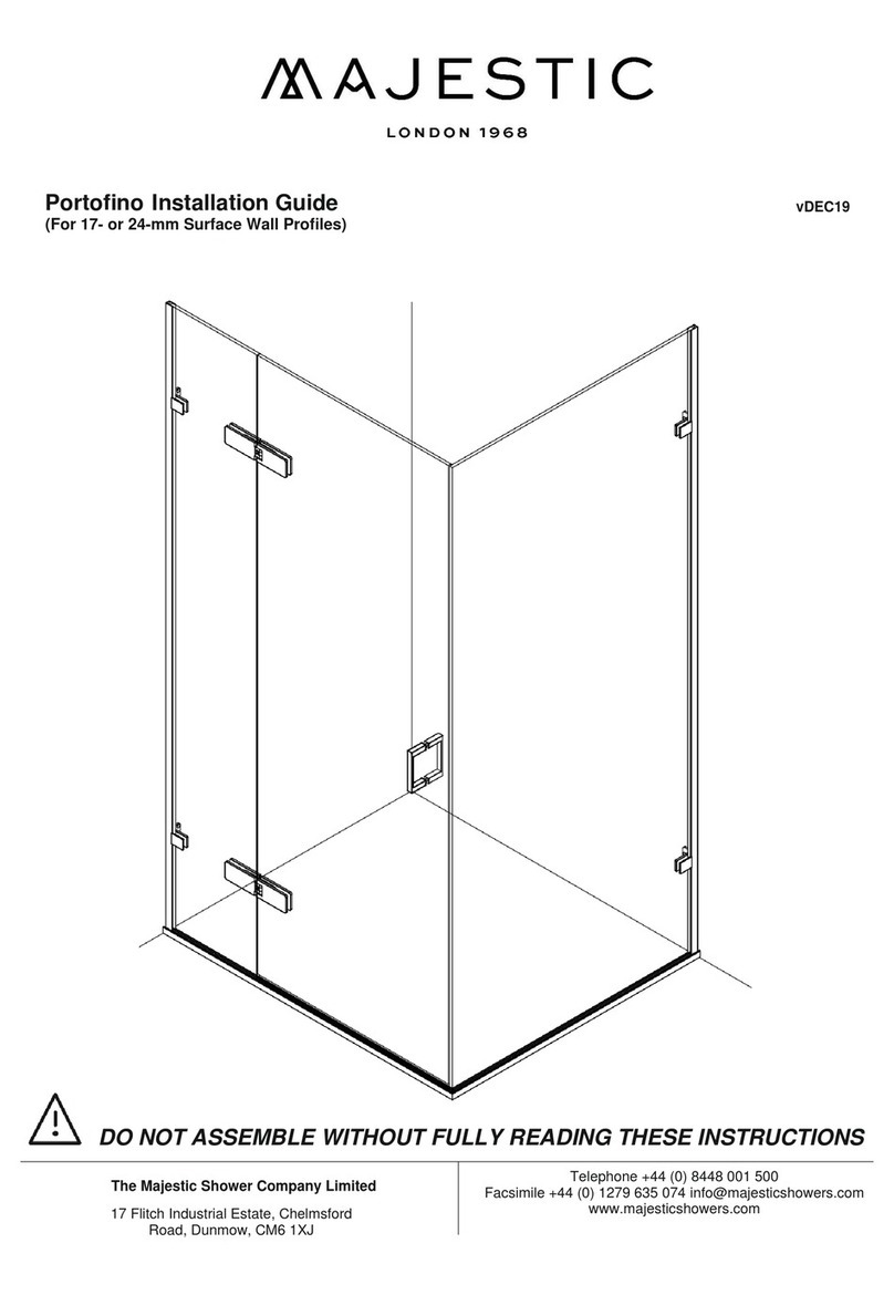
Majestic Deauville Corner Enclosure User manual

majestic
installation guide
—
deauville corner enclosure
for units with 24mm wall
and floor surface profiles,
without an underfr ame

The Majestic Shower Company Limited
One North Place, Edinburgh Way, Harlow Essex
CM20 2SL England,
Telephone +44 (0) 8448 001 500
Facsimile +44 (0) 1279 635 074
info@majesticshowers.com www.majesticshowers.com
These Instructions are for a left and right
handed unit. The diagrams show a left handed
unit. You will have to determine which hand of
unit you have before work commences.

The Majestic Shower Company Limited
One North Place, Edinburgh Way, Harlow Essex
CM20 2SL England,
Telephone +44 (0) 8448 001 500
Facsimile +44 (0) 1279 635 074
info@majesticshowers.com www.majesticshowers.com
Deauville Corner Enclosure
YOUR KIT SHOULD CONTAIN THE FOLLOWING:
Vertical wall profile x2
Horizontal Floor Profile x3
Black rubber strips x3
1xrecaps mm01
Glass door panel x1
Glass in-line panel x2
Glass return panel x1
Glass-to-glass hinges x2
Glass-to-wall brackets x4
(inc. Rawl plugs, screws, screw covers)
Glass-to-glass bracket x1
2mm Allen key x1
4mm Allen key x1
Door mounting blocks x2
1936 glass-to-door seal x2
1915 under-door seal x1
Door handle set x1
TOOLS REQUIRED:
2x suction glass lifters
Spirit Level
Setsquare
Power drill/driver
Hacksaw
Junior Hacksaw
Fine tooth file
Sealant gun
High-quality silicone
Pencil
Metal Scriber
Masking tape
Measuring tape
IMPORTANT:
Please check the glass and all components thoroughly
before installation; if any of the parts have been supplied
incorrectly or are damaged, contact Majestic immediately.
Any faults with the product found after installation cannot
be rectified and Majestic will not be held responsible for
re-installation of faulty or marked goods.
Unwrap all parts carefully to avoid damaging the chrome
fittings!
This unit must be fitted on a level surface, unless the
glass has been cut to suit any slope in the floor.
Whether fitting to a tiled floor or tray, ensure the area
is degreased, dust free and level.
Do not place the glass panels on hard surfaces! Cover
any hard surfaces you are working on with a cushioned
material, to help prevent the glass from shattering on
contact.
Before commencing the installation, please familiarise
yourself with the glass-handling guide attached to the
glass panels. Where appropriate, the top end of the
glass panels will be indicated.
If you have purchased anti-calcium glass, the treated
side of the glass will be indicated and should always
face towards the inside (wet side) of the shower
enclosure.
Certain sections of the installation of this shower
enclosure require two people.

The Majestic Shower Company Limited
One North Place, Edinburgh Way, Harlow Essex
CM20 2SL England,
Telephone +44 (0) 8448 001 500
Facsimile +44 (0) 1279 635 074
info@majesticshowers.com www.majesticshowers.com
AB
D
(D)
AB
D
(D)
3Before cutting the horizontal profiles, you will also have to
consider whether the walls that the panels will be fixed to
are leaning in or out.
A: If wall leans in at top: leave extra length on the profile; cut
off less than 9mm.
B: If wall leans out at the top;the profile needs to be shorter;
cut off more than 9mm.
4If the unit is being installed on a tray the position of the profiles
in relation to the lip of the tray must also be considered. Ideally
the outer edge of the profiles should sit 10mm back from the
front edge of the tray.
1
The horizontal profiles are supplied at maximum adjustment
length and have been mitred as a guide, but it is likely you will
have to cut them down.
Before setting out the horizontal profiles you will have to
determine how much you will need to cut off in-line profile A
and the return profile.
2
If you cut 9mm off the square end of the profiles, then the
glass panels will sit in the centre of the vertical wall profile
adjustment.
Before cutting the horizontal profiles, make sure the glass
in-line and return panels will fit into their floor profiles after
you have cut them down.
(Size of profile A
after cutting)
(In-line profile B)
(Door panel C + 9mm)
Glass
Return
Panel
10mm
Spacer
(5 mm) (5 mm)
Floor
Floor profile
Profile
Wall Glass
(In-line profile A)
(In-line profile B)
(Return profile)
(Door)

The Majestic Shower Company Limited
One North Place, Edinburgh Way, Harlow Essex
CM20 2SL England,
Telephone +44 (0) 8448 001 500
Facsimile +44 (0) 1279 635 074
info@majesticshowers.com www.majesticshowers.com
(In-line profile A)
(In-line profile B)
(Return profile)
(Door)
(Size of profile A
after cutting)
(In-line profile B)
(Door panel C + 9mm)
Glass
Return
Panel
10mm
Spacer
(5 mm) (5 mm)
Floor
Floor profile
7
Insert the 10mm spacer into the horizontal return profile, and
use it to align the vertical wall profile. Push the mitred ends
together, and use a spirit level to ensure the wall profile is
plumb vertical.
Mark the screw holes; remove the vertical wall profile. Drill
4.5mm holes; insert Rawl plugs.
8
Reposition the vertical wall profile, and insert the top and bottom
screws to hold it place. Insert a rubber strip into the horizontal
return profile. Using the suction glass lifters, lift the glass return
panel into the profile.
Make sure the return panel is plumb vertical; pack it up with 3”
rubber strips if necessary, taking note of their positions. Do not
use more than three strips of rubber under the panel.
(Size of profile A
after cutting)
(In-line profile B)
(Door panel C + 9mm)
Glass
Return
Panel
10mm
Spacer
D
(D)
5
Measure the width of the inline profiles A and B and the glass
door panel C in mm and write the results into the boxes below;
it is important to measure to the tips of the mitred ends of the
profiles. Use the formula A +B +C +9 to calculate D:
6
Make a mark on the tray or floor Dmm along the wall. Place
the outside of the horizontal return profile inside the mark,
perpendicular to the wall. Ensure the mitred end is pushed into
the corner, tape the profile into place and mark its position.
At this point, double check the measurements of the door and
in-line panels to make sure the door gap is correct.
(Size of profile A
after cutting)
(In-line profile B)
(Door panel C + 9mm)
Glass
Return
Panel
10mm
Spacer
D
(D)
Example
+ + + 9 =
+ + + 9 =
400 400 700 1509
A B C D

The Majestic Shower Company Limited
One North Place, Edinburgh Way, Harlow Essex
CM20 2SL England,
Telephone +44 (0) 8448 001 500
Facsimile +44 (0) 1279 635 074
info@majesticshowers.com www.majesticshowers.com
(Size of profile A
after cutting)
(In-line profile B)
(Door panel C + 9mm)
Glass
Return
Panel
10mm
Spacer
(D)
Glass
Return
Panel
10mm
(Size of profile A
after cutting)
(In-line profile B)
(Door panel C + 9mm)
Glass
Return
Panel
10mm
Spacer
(D)
Glass
Return
Panel
10mm
1 1
Put the brackets to one side and use the suction glass lifters to
remove the glass return panel. Remove the horizontal return
profile; unscrew and remove the vertical wall profile. Drill 7mm
holes where marked on the wall; insert Rawl plugs.
12
Run a bead of silicone along the wall side of the vertical wall
profile, and screw it tightly into place. Loosely screw the glass-
to-wall brackets to the wall.
Glass
Return
Panel
10mm
Spacer
9
Using a metal scriber, mark the vertical profile level with the top
of the glass. The glass return panel can be moved backwards or
forwards in the return profile to help you position the front
profiles, but the glass must be inside the vertical wall profile by
at least 5mm along its entire height.
10
Disassemble two glass-to-wall brackets, being careful not to
damage the faceplates. With the clear plastic gaskets inserted
and wall screw plates facing inwards, align the brackets centrally
to the holes in the glass return panel; hold them in place and
mark the screw holes.
Glass
Return
Panel
10mm
Spacer

The Majestic Shower Company Limited
One North Place, Edinburgh Way, Harlow Essex
CM20 2SL England,
Telephone +44 (0) 8448 001 500
Facsimile +44 (0) 1279 635 074
info@majesticshowers.com www.majesticshowers.com
Glass
Return
Panel
10mm
Spacer
Glass
Return
Panel
10mm
Spacer
15
As shown, run beads of silicone along the inside of the vertical
wall profile and the horizontal return profile only, not the front
inline profile. 16
Using the suction glass lifters, replace the glass return panel
into the silicone-lined profiles; remember to leave a 10mm
gap for the glass inline panel, as shown. Use the 10mm
spacer to help.
Glass
Return
Panel
10mm
Spacer
13
Run a bead of silicone along the base of the horizontal return
profile, and reposition it on the tray or floor where marked; use
the 10mm spacer to ensure it is aligned with the vertical wall
profile and push the mitred ends together; tape into position.
Remove the 10mm spacer and apply a generous amount of
silicone into the corner joint. Reinsert the noted rubber strips
into the horizontal return profile.
14
Use the 10mm spacer to align horizontal inline profile B to the
end of the horizontal return profile, so the mitred ends fit
together; tape the profile into place and mark its position.
The horizontal inline and return profiles must be at 90°
to one another.
Glass
Return
Panel
10mm
Spacer

The Majestic Shower Company Limited
One North Place, Edinburgh Way, Harlow Essex
CM20 2SL England,
Telephone +44 (0) 8448 001 500
Facsimile +44 (0) 1279 635 074
info@majesticshowers.com www.majesticshowers.com
A
B
A
B
Glass
Return
Panel
10mm
Spacer
17
Loosely fix the faceplates to the glass-to-wall brackets through
the holes in the glass return panel; fully tighten the wall screws.
Ensure the glass return panel is plumb vertical, then fully tighten
the glass-to-wall bracket faceplates.
18
Align the profiles A and B across the front. Ensure the mitred end
is pushed into the corner, tape the profile into place and mark
its position.
Double check that inline profile A aligns with inline profile B.
Also check at this point that the gap between the profiles A + B
is equal to the width of the glass door panel + 9mm.
19
Insert the 10mm spacer into horizontal inline profile A, and use it
to align the second vertical wall profile. Push the mitred ends
together, and use a spirit level to ensure the wall profile is plumb
vertical.
Mark the screw holes; remove the vertical wall profile. Drill
4.5mm holes; insert Rawl plugs.
20
Reposition the vertical wall profile, and insert the top and bottom
screws to hold it place. Insert a rubber strip into horizontal inline
profile A. Using the suction glass lifters, lift glass inline panel A
into the profile.
Make sure inline panel A is plumb vertical and level with the
return panel; pack it up with 3” rubber strips if necessary, taking
note of their positions. Do not use more than three strips of
rubber under the panel.

The Majestic Shower Company Limited
One North Place, Edinburgh Way, Harlow Essex
CM20 2SL England,
Telephone +44 (0) 8448 001 500
Facsimile +44 (0) 1279 635 074
info@majesticshowers.com www.majesticshowers.com
22 Put the brackets to one side and use the suction glass lifters to
remove the glass inline panel. Remove horizontal inline profile A;
unscrew and remove the vertical wall profile. Drill 7mm holes
where marked on the wall; insert Rawl plugs.
21
Disassemble the remaining two glass-to-wall brackets, being
careful not to damage the faceplates. With the clear plastic
gaskets inserted and wall screw plates facing inwards, align the
brackets centrally to the holes in the glass return panel; hold
them in place and mark the screw holes.
A
B
23 Run a bead of silicone along the wall side of the vertical wall
profile, and screw it tightly into place. Loosely screw the glass-
to-wall brackets to the wall.
A
B
24
Run a bead of silicone along the base of horizontal inline profile
A, and reposition it on the tray or floor where marked; use the
10mm spacer to ensure it is aligned with the vertical wall profile
and push the mitred ends together; tape into position.
Remove the 10mm spacer and apply a small amount of silicone
into the corner joint. Reinsert the noted rubber strips into
horizontal inline profile A.

The Majestic Shower Company Limited
One North Place, Edinburgh Way, Harlow Essex
CM20 2SL England,
Telephone +44 (0) 8448 001 500
Facsimile +44 (0) 1279 635 074
info@majesticshowers.com www.majesticshowers.com
25
As shown, run beads of silicone along the inside of the vertical
wall profile and horizontal inline profile A only. 26
27
Loosely fix the faceplates to the glass-to-wall brackets through
the holes in glass in-line panel A.
Ensure glass inline panel A is plumb vertical and level with the
return panel, then fully tighten the glass-to-wall bracket
faceplates.
28
Disassemble the glass-to-glass bracket, being careful not to
damage the polished surfaces.
Fit the inner part of the bracket to the glass return panel, so the
clear plastic gasket is aligned with the edge of the glass. Attach
the faceplate through the hole in the glass.
Using the suction glass lifters, replace glass inline panel A into the
silicone-lined profiles.

The Majestic Shower Company Limited
One North Place, Edinburgh Way, Harlow Essex
CM20 2SL England,
Telephone +44 (0) 8448 001 500
Facsimile +44 (0) 1279 635 074
info@majesticshowers.com www.majesticshowers.com
Door Panel Fixed Panel
90° 90°
Hinge
packer
Hinge
packer
29
Insert a rubber strip into horizontal inline profile B. Use the
suction glass lifters to carefully lift the glass inline panel into its
profile. Align the end of the glass inline panel with the end of the
glass return panel, top and bottom; pack it up with rubber strips
if necessary, taking note of their positions. Check the panel sits
plumb vertical.
2
Door Panel Fixed Panel
90° 90°
Hinge
packer
Hinge
packer
30
Using the suction glass lifters, remove glass inline panel B. Un-
tape and remove the horizontal inline profile.
31
Run a bead of silicone along the underside of the horizontal
inline profile, and reposition it on the floor where marked; tape
in place. Use the 10mm spacer to ensure it is aligned with the
horizontal return profile and push the mitred ends together.
Remove the 10mm spacer and apply a small amount of silicone
into the joint. Reinsert the noted rubber strips into the
horizontal inline profile.
Door Panel Fixed Panel
90° 90°
Hinge
packer
32
Run beads of silicone along the inside of the horizontal inline
profile, as shown.

The Majestic Shower Company Limited
One North Place, Edinburgh Way, Harlow Essex
CM20 2SL England,
Telephone +44 (0) 8448 001 500
Facsimile +44 (0) 1279 635 074
info@majesticshowers.com www.majesticshowers.com
33
Using the suction glass lifters, replace the glass inline panel into
the horizontal inline profile. Loosely attach the glass-to-glass
bracket faceplate, and adjust the inner apart of the bracket so it
fits snugly between the glass inline and return panels; fully
tighten both faceplates with the Allen key. Check that all panels
sit plumb vertical and level with one another.
34
To protect glass in-line panel B from being
damaged you can slide one of the vertical 1936
seals (1) onto its exposed vertical edge; cut the
seal to size.
1
Door Panel Fixed Panel
90° 90°
Hinge
packer
Hinge
packer
35
Insert a black rubber hinge packer into the in-line panel hinge
slots as shown. Disassemble the hinges, being careful not to
damage the polished surfaces. Place the hinges and faceplates
either side of the hinge slots in the glass in-line panel, with
gaskets inserted and Allen bolts facing inwards; loosely screw
the hinges and faceplates together.
Use a set square to ensure the hinge sits at 90° to the edge
of the glass.
Door Panel Fixed Panel
90° 90°
Hinge
packer
Hinge
packer
36
Steps 36-37 require one person to support the glass
door panel at all times, while another person must be
inside the enclosure with faceplates, gaskets and screws. Insert
a black rubber hinge packer in the door hinge slots as shown.
Position the door mounting blocks on the tray or floor. Using the
suction glass lifters, lift the glass door panel onto the mounting
blocks; be careful not to chip the edges of the glass against
each other.

The Majestic Shower Company Limited
One North Place, Edinburgh Way, Harlow Essex
CM20 2SL England,
Telephone +44 (0) 8448 001 500
Facsimile +44 (0) 1279 635 074
info@majesticshowers.com www.majesticshowers.com
37
Position the hinges centrally in their slots. With gaskets inserted,
loosely screw the hinges and faceplates together through the
glass door panel slots.
Adjust the door so it is level with the two glass panels; the
gaskets should be neat and flush, and the end of the glass door
should not protrude beyond the hinges. Tighten the Allen bolts.
38
The other 1936 door-to-glass seal (2) should
be cut into three pieces to fit vertically above,
between and below the hinges on the end of
the door.
Open the door outwards and slide the sections
into place on the door. If necessary, adjust the
door on its hinges so that it closes correctly
onto the in-line panel seal.
2
39
Mark the width of the glass door panel on
the 1915 under-door seal (3); cut the seal
to length, and slide it onto the bottom of
the door.
40
Trim the 45° internal blade off the 1915 under-door seal so it
misses the vertical 1936 seal.
3

The Majestic Shower Company Limited
One North Place, Edinburgh Way, Harlow Essex
CM20 2SL England,
Telephone +44 (0) 8448 001 500
Facsimile +44 (0) 1279 635 074
info@majesticshowers.com www.majesticshowers.com
41
Disassemble the handle, being careful not to damage the
chrome surfaces; fit the handle to the door. 42
Attach the overhead support bar and the 45° support arm if
supplied.
43
Make sure all screws and fittings are tight (especially the 4mm
Allen bolts on the hinges). Tighten to 12 N·m. Dab the cover
caps with silicone and place the caps on the 90° glass-to-glass
and glass-to-wall brackets. Caps are not provided for the
polished hex Allen bolts on the hinges.
44
Tape the glass return and in-line panels together as shown, and
run a bead of silicone down the length of the joint on the inside
of the enclosure; leave silicone to fully cure for 24 hours before
un-taping.

The Majestic Shower Company Limited
One North Place, Edinburgh Way, Harlow Essex
CM20 2SL England,
Telephone +44 (0) 8448 001 500
Facsimile +44 (0) 1279 635 074
info@majesticshowers.com www.majesticshowers.com
Table of contents
Other Majestic Plumbing Product manuals
Popular Plumbing Product manuals by other brands

Kessel
Kessel Ultraflat 54 quick start guide

Laufen
Laufen Kartell 3.1233.6.090.120.1 technical information

Pegasus
Pegasus 67122-8004 installation instructions

Elkay
Elkay EWS2520 Specifications

American Standard
American Standard Silhouette 7163.001 Specification sheet

ALT
ALT Exporondo 90520 Installation & Care Guide

IB RUBINETTERIE
IB RUBINETTERIE ELIO EO394 FITTING INSTRUCTION

Brizo
Brizo SOLNA 63920LF quick start guide

American Standard
American Standard Retrospect Collection Right Heigh Elongated Toilet... Specifications

BELLOSTA
BELLOSTA Revivre Young Installation instruction

GATTONI
GATTONI KUBIK 2537 Installation and assembly

Grohe
Grohe GROHTHERM MICRO 34 487 installation instructions