Major tech MT190 User manual

INSTRUCTION MANUAL
CIRCUIT BREAKER FINDER
MT190

2

3
Contents Page no
1. Introduction.....................................................................................4
2. Features...........................................................................................4
3. Safety..............................................................................................4
3.1. International Safety Symbols......................................................4
3.2. Safety Precautions....................................................................4
4. Meter Description..............................................................................5
5. Specifications...................................................................................6
5.1. Electrical Specifications..............................................................6
6. Operation.........................................................................................7
6.1. Auto Ranging Multimeter............................................................7
6.1.1. AC/DC Voltage Measurements.........................................7
6.1.2. AC/DC Current Measurements.........................................7
6.1.3. Resistance Measurements..............................................7
6.1.4. Continuity Check............................................................8
6.1.5. Diode Test.....................................................................8
6.1.6. MAX Hold Button............................................................8
6.1.7. Hold Button...................................................................8
6.1.8. Auto Power Off..............................................................8
6.1.9. Replacing the Battery.....................................................8
6.1.10. Replacing the Fuses.......................................................9
6.2. Wire/Cable tester (Tone generator and Amplifier probe) ..................
Operation................................................................................9
6.2.1. Cable/Wire Tracing.........................................................9
6.2.2. Identifying Telephone Cable Tip and Ring – Using ................
Alligator Clips................................................................9
6.2.3. Identifying Telephone Cable Tip and Ring – Using ................
the RJ-11 Connectors...................................................10
6.2.4. Identifying Telephone Cable Line Condition.....................10
6.2.5. Continuity Testing........................................................10
6.2.6. Tone Selection.............................................................10
6.2.7. Low Battery Indicator....................................................10
6.2.8. Battery Replacement....................................................11
4
1. INTRODUCTION
The MT190 is a Circuit Breaker Finder system that operates on energized
circuits, consists of a Transmitter, which plugs into the socket on the circuit
you wish to isolate and a Receiver Scanner. The Transmitter sends signals
along the cable to the distribution board, the operator simply runs the
Receiver Scanner along the circuit breakers or fuses, and the scanner will
automatically identify the correct breaker by means of a green LED and a
continuous buzzer tone. An added feature is the convenient chart printed on
the Transmitter that helps determine the wiring condition of the socket
outlet, based on the LED lights results. Conditions indicated are Correct
Wiring, Open Ground, Reverse Polarity, Open Live, Open Neutral and
reverse Live and Ground. There is also a 30mA RCD test function built into
the MT190 Transmitter.
2. SAFETY
Ÿ Before each use, verify tester operation by testing on a known live and
correctly wired receptacle and circuit.
ŸDo not use if the tester appears damaged in any way.
ŸThe tester is intended for indoor use only.
ŸThe tester is designed for use with 250V AC electrical systems, do not
connect to higher voltage electrical supplies.
Ÿ Other equipment or devices attached to the circuit being tested could
interfere with the tester, clear the circuit before testing.
Ÿ This tester only detects common wiring problems, always consult a
qualified electrician to resolve wiring problems.
Ÿ If using accessories to connect to bare wires ensure that the circuit is not
energized before inspecting, applying, or removing the transmitter.
ŸExercise extreme caution around energized, bare wires, especially when
working in or around an open breaker panel.
Ÿ Do not use in cardiac care areas.
WARNING: To ensure safe operation and service of the meter, follow
these instructions, failure toobserve these warnings can result in
severe injury or death.
WARNING: observe the instructions given in this manual;
improper use could damage the instrument or its components.
This symbol adjacent to another symbol, terminal or
operating device indicates that the operator must refer to
an explanation in the Operating Instructions to avoid
personal injury or damage to the meter.
This WARNING symbol indicates a potentially hazardous
situation, which if not avoided, could result in death or
serious injury.
This CAUTION symbol indicates a potentially hazardous
situation, which if not avoided, may result damage to the
product.
Safety Symbols

5
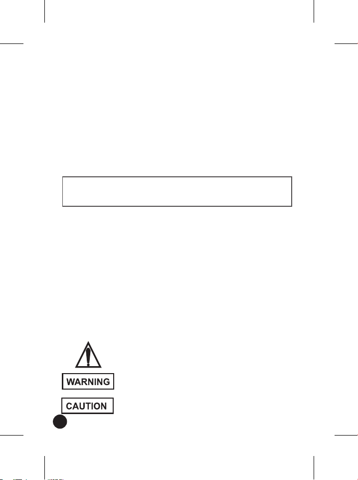
3. METER DESCRIPTION
Receiver
1 - Plug
2 - RCD Test Button
3 - Receptacle LED Coding
Scheme
4 - Receptacle LED’S Indicator
• There is no switch for the
transmitter.
• It will automatically start
the injection of the test
signal upon connection to a
mains supply.
Transmitter
1 - Scanning Head
2 - LED indicator , light red
during auto scanning.
3 - Signal LED indicator, light
green for correct.
4 - Buzzer , Bleeps to indicate
auto scanning and Rapid or
continuous tone to indicate
correct breaker found.
5 - ON/OFF/RESET button , Press
and hold to switch off, Press
and release to switch onor
reset during scanning.
6 - Battery cover
TRANSMITTER
RECEIVER
1
2
3
5
4
6
1
3
2
4

6
4. OPERATIONS
4.1. Transmitter
There is no switch for the transmitter. It will automatically start the
injection of the test signal upon connection to a mains supply.
4.2. Receiver
The membrane switch on the receiver has 3 functions-On/ReseVOff.
Push and immediately release the switch when the receiver is off-this will
tum the unit on with a steady beeping and red LED Indicating that the
scanning function is in progress.
Push and immediately release the switch when the receiver is on-th is will
reset all scanning function memories to zero, ready to start again, with a
steady beeping and red LED. Always use the reset function away from the
distribution board so that no signal is present during reset.
Push and hold switch down for over 1 second - this will turn the receiver
off.
Note: To maximize battery life an auto-power off function is incorporated
in the receiver which will turn the receiver off after three minutes of
inactivity. To resume testing after this period just turn the unit on as
described above. (Press and release to switch on or reset, Press and hold
to switch unit off.)
4.3. Principles of automatic scanning
As the receiver works by comparing the strength of signal received from
one breaker with another it is essential to compare like with like.
Observe the following for best results.
Do not let the scanning head wander around. To operate well the
automatic scanning memory needs a consistent signal.
Keep the red scanning head at the same angle relative to the breaker or
fuses for the duration of the test.
Keep the head in contact with the breaker during each sweep to ensure
consistency in the proximity of the head to the breaker.
Test only the same side of each breaker during a test .Pay particular
attention to this when testing a vertically hung panel which may have
neighbouring breakers mounted in opposite directions.
Always reset the receiver (away from the distribution board) before
changing any test condition.
4.4. Receptacle Wiring Test
1. Plug the Transmitter/Receptacle tester into the outlet.
2. The three LED's will indicate circuit condition, the diagram lists all of the
conditions that the tester can detect. the LED"s in this diagram
represent the view from the GFCI button side of the transmitter, when
viewing the other side of the transmitter the LED's will be a mirror image
of those shown here.

WARNING: To avoid electric shock, disconnect power to the unit
under test and discharge all capacitors before taking any resistance
measurements. Remove the batteries and unplug the line cords.
CAUTION: Do not measure AC/ DC voltages if a motor on the circuit
is being switched ON or OFF. Large voltage surges may occur that can
damage the meter.
7
3. The tester will not indicate the quality of the ground connection, 2 hot
wires in a circuit. a combination of defects, or reversal of ground and
neutral conductors.
4.5. Receptacle RCD Test
1. Before using the tester. press the TEST Button on the installed RCD
receptacle. the RCD should trip.
• If it does not trip. do not use the circuit and call a qualified
electrician.
• If it does trip. press the RESET Button on the receptacle.
2. Plug the Transmitter/Receptacle tester into the outlet. verify that the
wiring is correct as described above.
3. Press and hold the test button on the tester for at least 8 seconds. the
indicator lights on the tester wi ll shut off when the RCD trips.
4. lf the circuit does not trip. either the RCD is operable but the wiring is
incorrect. or the wiring is correct and the RCD is inoperable.
4.6. Function Check
• Function check
Before use prove that unit is functioning correctly. To do this switch the
receiver on and firstly check that the LED is red and a steady beeping
tone is emitted .
If either of these functions is not present replace the battery in the
receiver before proceeding. When battery power is low the green led
flashing and the beeping tone will have a longer duration, then the
meter shut down quickly. The battery will have around 20% of its
capacity left at this stage and will shortly require replacement.
Connect the transmitter to the mains and move the scanning head over
the face of the transmitter.
The frequency of the beeping should become very rapid or change to a
continuous tone and the LED should turn Green when the scanning
head is detecting a signal "hotspot" (this is good practice for scanning,
as the indication is similar to finding the correct fuse at the board.)
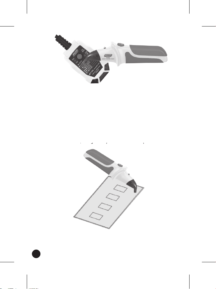
8
(Run the scanning head over the transmitter to check the fuse Finder is
operating correctly).
• Advice for best performance
Due to the differing designs of circuit breakers it may sometimes be
unclear from the above procedure which of two breaks the strongest
signal comes from, particularly if it appear to come from a boundary
area between two adjacent breaker. In the event of this occurring one
of the following variations should enable clear identification.
4.7. Finding the Circuit Breaker or Fuse
1. Scan the breaker on the opposite side of the switch (after resetting the
receiver). The strongest signal may be found at the top of the breaker.
9
2. Rotate the receiver (after resetting) through 90 to set the black pips on
the insert of the red scanning head to come towards being in line with
the breaker. At some point a stronger signal will be found-scan at the
new angle.
• Fuse finding process
1. Plug the transmitter into the socket under test and switch the socket
on. The red LED on the transmitter should light.
2. Go to the consumer unit or fuse box .. Turn on the receiver. A steady
beeping tone will be emitted and the LED on the receiver will light
red to indicate automatic scan.
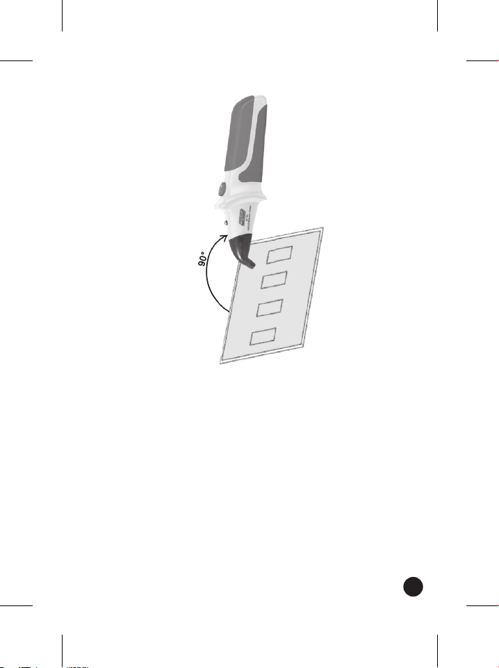
3. Place the scanning head in contact with the face of the circuit
breaker or fuses at a right angle to the direction of the breaker body
and run the scanning head steadily along the row of circuit breakers.
The frequency of the beeping will increase to a very rapid or
continuous tone and the LED will tum from red to green when the
receiver encounters a stronger signal

10
(Continue scan slowly across the face of the circuit breakers or fuses)
(Sometimes we have noticed some problems. When the receiver is
getting closer to correct circuit breaker, the red LED start flashing
and there is no LED indication for long time after detecting circuit
breaker.
These are normal.
Because the receiver in search and search for weak signal , We can
press the RESET key, new search for signals. And then you get the
strongest signal, the red light turn off, green LED lighting and
continuous tone.)
Important the first stronger signal you encounter may not be
the strongest there is.
Do not slop scanning when a stronger signal is first
encountered. Because the scanning technology used is
comparative, it is essential to continue scanning all of the
breaker that may protect the outlet under test.
4. Repeat the scan of the row of breaker. With each sweep the receiver
will automatically adjust it is sensitivity and disregard weaker signals.
5. Continue scanning until the correct indication (rapid or continuous
tone and LED lit green) is given only when the scanning head is over
one breaker or fuse. This is the breaker protecting the circuit that the
transmitter is plugged into.
Popular Camera Accessories manuals by other brands

Viltrox
Viltrox EF-NEX Mount instructions

Calumet
Calumet 7100 Series CK7114 operating instructions

Ropox
Ropox 4Single Series User manual and installation instructions

Cambo
Cambo Wide DS Digital Series Main operating instructions

Samsung
Samsung SHG-120 Specification sheet

Ryobi
Ryobi BPL-1820 Owner's operating manual


