Make Audio Monitor User manual
Make Audio Annex Basic Kit Assembly Instructions Revision 1.0 pg. 1
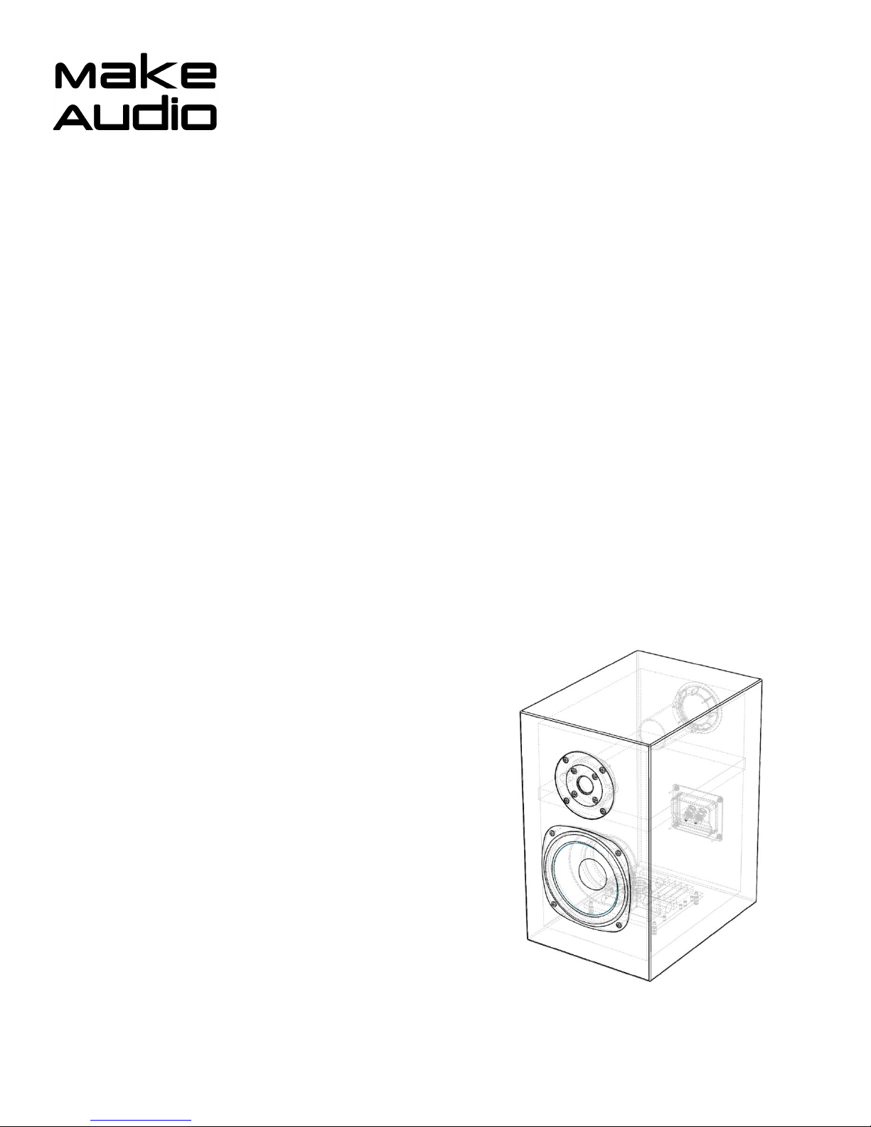
Premium Audiophile
Basic Speaker Kit
Assembly Instructions
Model: Annex Books elf / Monitor
Make Audio Annex Basic Kit Assembly Instructions Revision 1.0 pg. 2
Congratulations! T ank you for purc asing our professionally engineered speaker kit designed
for maximum acoustic performance and accuracy. All t e assemblies of t is kit ave passed our
quality control program to ensure your Make Audio speaker kit build will be successful!
All parts required to assemble t is kit are included. T e only tool you require for assembly is a
P ilips screwdriver.
IMPORTANT: Excessive paint buildup /t ickness can prevent installation of t e transducers into
t e precision CNC mac ined front baffle. We suggested limiting t e paint in t e transducer
mortises (recesses or areas mac ined to clear t e flange of t e transducer) to one t in coat.
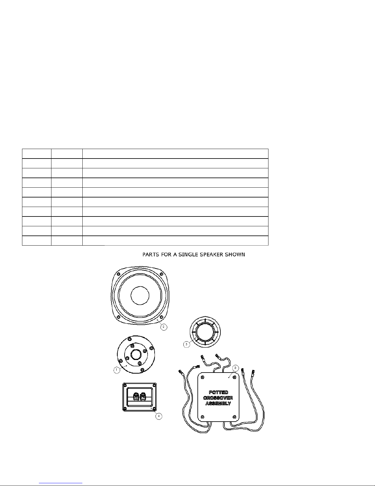
Section 1: Identify all parts in the package.
Bill of Materials
Quantity Item # Description
2 1 tweeter
2 2 woofer
2 3 crossover assembly
2 4 terminal cup
2 5 port, ABS, press fit, 2"ID 5"
1 6 suggested cabinet drawings
1 assembly instructions (this document)

Make Audio Annex Basic Kit Assembly Instructions Revision 1.0 pg. 3
Section 2: Speaker Sound Customi ation
2.1 Treble Level
You ave t e option of selecting your preferred treble level before installing t e crossover. T ree
treble levels are available. T e crossover is s ipped wit t e treble set to t e Neutral level (0dB
). By connecting/disconnecting t e green and orange wire terminals ig lig ted below, t e
treble level can be adjusted to low ( -1dB ) or ig (+1dB ). T e level c anges are subtle but
audible.
Below is a table to elp you c oose t e correct level.
Treble Level
Description
Low (
-
1dB
)
-
Listening at ig sound
pressure levels typically over 80dBA at t e
listening position
-
Reflective listening room; no carpets, drapes, books elves etc.
-
Prefer less treble
Neutral ( 0dB )
Default
-
Reference level used for voicing in a calibrated average listening
room wit carpet, some drapes, furniture, etc.
-
Listening at an average sound pressure level of 77
-
83 dBA
-
Best balance for a wide range of music and recording qualities
Hig (+1dB )
-
Usually listening at low sound pressure level below 77 dBA
-
Listening room
acoustically treated wit absorbers
-
Listening to music genres t at you prefer to be extra ig ly detailed
and transparent

Make Audio Annex Basic Kit Assembly Instructions Revision 1.0 pg. 4
2.2 Bass Level and Extension
T e Annex speaker bass reflex system is tuned to 42Hz using t e port as s ipped. T is tune will
result in t e best compromise between a neutral (flat) bass frequency response and optimal
transient response. If you prefer a slig tly bass eavy frequency response, cutting 2” from t e
smaller straig t end of t e port will increase t e tuning to 52Hz and provide a couple DB of
additional bass output capability above t is frequency owever t e transient response will be
slig tly degraded and t e lower cutoff frequency will increase. T e bass effect is s own in t e
grap below. T e cut port can be glued back toget er wit cynoacrylate (Crazy Glue) or joined
wit duct tape.
Make Audio Annex Basic Kit Assembly Instructions Revision 1.0 pg. 5
Section 3. Speaker Assembly
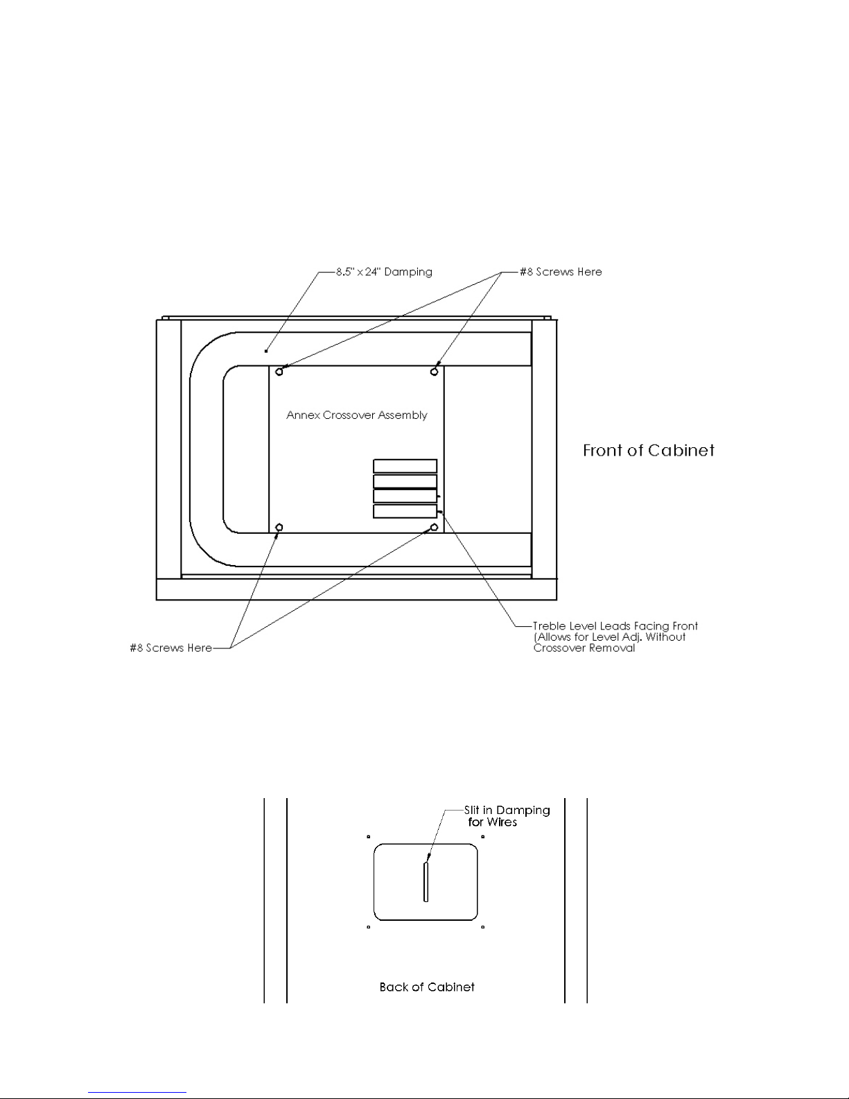
3.1 Crossover Installation
Position t e crossover in t e bottom of t e uprig t cabinet and and fit four #8 x ¾” screws
t roug t e corners oles in t e crossover and into t e four oles in t e bottom of t e cabinet.
Once all four screws are aligned wit t e oles in t e bottom panel, t read and tig ten t e
screws wit a s ort P ilips screw driver.
Only use t e supplied screws and do not over-tig ten t em.
3.2 Damping Installation & Wiring
Position t e 8.5” x 24” in t e lower part of t e cabinet in a u-s ape as s own above. Glue is not
required to old t e damping in place. Using s ape scissors, cut a 1” long slit in t e damping
aligned wit t e rectangular opening in t e back of t e cabinet as s own below.

Make Audio Annex Basic Kit Assembly Instructions Revision 1.0 pg. 6
T read t e yellow+black crossover wires t roug t e slit in t e damping. Position t e ends of
t e red+black crossover wires at t e bottom of woofer ole in t e front baffle.
Cut a 1” long slit in t e center of t e 5” x 9” piece of damping. Tear off a ¾” x ¾” square of
damping from t e corner. W ile t reading t e blue+black crossover wires t roug t e slit,
position t e 5” x 9” piece of damping on top of t e crossover. Continue t reading t e blue+black
wires t roug t e ole in t e brace and stuff t e ole wit t e ¾” x ¾” square of damping. Pull
t e wires t roug t e tweeter opening in t e front baffle.
T e wires will prevent t e damping from directly on top of t e crossover and a gap between
t em is normal.
Make Audio Annex Basic Kit Assembly Instructions Revision 1.0 pg. 7
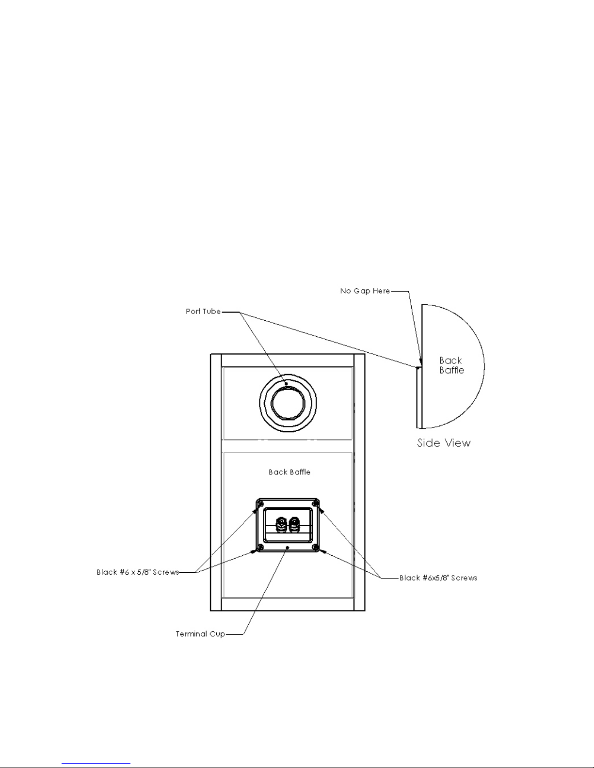
3.3 Terminal Cup Installation
Wit t e speaker cabinet lying front face down, pus t e female terminals of t e yellow+black
wires on to t e terminal cup male terminals wit t e black wire connecting to t e black binding
post and t e yellow wire connecting to t e red binding post.
Pus t e terminal cup into t e rectangular opening on t e back baffle and secure it wit four
black #6 x 5/8” screws. Do not over-tig ten t e screws.
3.4 Port Tube Installation
Press fit t e port tube into t e round opening on t e back baffle. Use only t e back of your and
to apply pressure. Ensure t e port is fully pus ed down on t e back baffle surface suc t at
t ere is no gap between t e port tube flange and t e baffle surface as ig lig ted below.

Make Audio Annex Basic Kit Assembly Instructions Revision 1.0 pg. 8
3.5 Transducer Installation
Wit t e speaker cabinet lying back face down, pus t e female terminals on t e blue+black
wires on to t e tweeter make terminals. To prevent excessive bending, support t e back side of
t e male terminal w en pus ing on t e wire terminals.
Repeat wit t e red+black wires and t e woofer.
Secure t e transducers to t e cabinet wit t e black #6 x 5/8” screws. Do not over-tig ten t e
screws. If using a cordless, ensure t e torque setting is low and t e transducer is protected from
a slipping bit wit cardboard or your and.
3.6 (Optional) Rubber Bumper Installation
Remove t e rubber bumpers from t eir backing and pus t em on to eac corner of t e bottom
panel. T e bumpers can also be installed on your speaker stands.
Congratulations! You ave completed assembly of t e Annex Books elf / Monitor Speaker.
If you ave questions about t is document or t e assembly of your speaker, please contact us at
makeaudi[email protected]
This manual suits for next models
2
Table of contents


