Makermade MASLOW CNC User instructions

SETTING UP YOUR MASLOW CNC
FROM THE MAKERMADE LEARNING LIBRARY
TABLE OF CONTENTS
1.0 What’s in Your Kit?
1.1 Building the Frame
1.2 Adding the Electronics
1.3 Building the Temporary Sled
1.4 Installing the Z-Axis
1.5 Calibrating Your Maslow
1.6 Building Final Sled

1.0 WHAT’S IN YOUR KIT?
FROM THE MAKERMADE LEARNING LIBRARY
THIS WORK IS LICENSED UNDER THE CREATIVE COMMONS ATTRIBUTION-SHAREALIKE 4.0 INTERNATIONAL LICENSE.
AC POWER CABLE
X/Y Motor Mounts(2)
RING BRACKET
X/Y MOTORS
ARDUINO MOTOR &SHIELD DC POWER SUPPLY
USB CABLE USB FLASH DRIVE
Z AXIS MOTOR CABLE
CHAINS(2)
RING BRACKET MOUNTS(3)RING BEARINGS(4) RING CARRIAGE(2)
X/Y MOTOR CABLES
Z AXIS MOTOR MOUNTS(2)Z AXIS MOTOR
1
5
9
13
2
6
10
14
3
7
11
15
4
8
12
16

WHAT’S IN YOUR KIT? PG. 2LAST UPDATE 05.31.19
HARDWARE BAGS
Attaches chains to frame
Multiple uses
Attaches carriages to ring
Cords, hardware for attaching
to frame
Fastens motor to mounts
Fastens L-brackets to ring,
and to sled
Holds bricks in place on sled
Attaches Arduino to frame
Attaches Z axis to router
and sled
BAG #1
BAG #4
BAG #7
BAG #2
BAG #5
BAG #8
BAG #3
BAG #6
BAG Z

1.1 BUILDING THE FRAME
TOOLS NEEDED:
Saw
Power Drill
Screwdrivers
Safety goggles
BUILD TIME:
About 5 hours, plus
glue drying time
COST:
Approximately $90
CUT LIST:
2x4s
(1)120”
(1) 88”
(2) 82”
(2) 79”
(2) 60”
(2) 34”
(2) 30”
(2) 28”
(2) 7”
(4)3.5”
MATERIALS LIST:
(7) 10’ long 2x4s
(1) 8’ long 2x4
(1) 6’ long 2x4
(1) 4X8 sheet .75” plywood
(75-100) 2.25” wood screws
Wood glue
Hardware & parts from kit
Note: Lumber dimensions are not critical, if 2x4s are not available in your area the local
equivalent will work. When cutting, try to keep the ends as square as possible, but small
errors in the lengths of any of the parts will not affect accuracy of the machine.
DESIGN BY THE MASLOW COMMUNITY, PARTICULARLY USERS DLANG AND MADGRIZZLE
Precision Level
Difficulty Level
THIS WORK IS LICENSED UNDER THE CREATIVE COMMONS ATTRIBUTION-SHAREALIKE 4.0 INTERNATIONAL LICENSE.
BEFORE BEGINNING
Acquaint yourself with
standard practices for
workshop safety.

BUILDING THE DEFAULT FRAME PG. 2LAST UPDATE 05.22.19
STEP 1: BUY MATERIALS
2X4 (or equivalent lumber)
6'
10'
10'
10'
10'
10'
10'
8'
PLYWOOD
PRO TIP:
Label the parts as you
cut them, you’ll be glad
you did.

BUILDING THE DEFAULT FRAME PG. 3LAST UPDATE 05.22.19
STEP 2: CUT OUT PIECES AS SHOWN
2X4 (or equivalent lumber)
120” TOP BEAM
88” REAR CROSSMEMBER
34” VERTICAL
34” VERTICAL
30” KICKER
30” KICKER
28” DIAGONAL 28” DIAGONAL
82” FRONT CROSSMEMBER: LOWER
82” FRONT CROSSMEMBER: UPPER
79” FRONT LEG
79” FRONT LEG
60” BACK LEG 60” BACK LEG
3.5” SPACER
3.5” SPACER
3.5” SPACER
3.5” SPACER
7” BEAM
7” BEAM
PLYWOOD

BUILDING THE DEFAULT FRAME PG. 4LAST UPDATE 05.22.19
FRONT LEG 79”
KICKER 30”
Spacer & back
leg both go
beneath kicker
11.5” 1.75”
FRONT LEG 79”
KICKER 30”
90º
KICKER
FRONT LEG
KICKER
FRONT LEG
BACK LEG
KICKER
SPACER
FRONT LEG
BACK LEG 60”
KICKER
FRONT LEG
BACK LEG 60”
SPACER
STEP 3/4A ATTACH KICKERS TO FRONT LEGS
•Kickers at 90° angle to front legs
•Kickers 11.5” from bottom of front legs, and
overhanging by 1.75”
•Screw through top of kickers into front legs
•Screw through top of kickers into spacers
•Flip each assembly over for next step
STEP 3/4C POSITION BACK LEGS
•Rotate back legs out to end of kickers
•Screw bottom of back legs to kickers
•Add more screws to top of back legs
STEP 3/4B ADD BACK LEGS
•Place back legs on top of front legs,
aligning bottom ends
•Mark center of back legs 1” from top end
•Screw through top center of back legs
into front legs at marked spot
•Only 1 screw per leg, NO GLUE
Next steps are most easily done
with front legs horizontal to floor,
as shown. Prop with scraps to keep
things level.
LEGS ARE NOW COMPLETE!
BUILDING THE DEFAULT FRAME PG. 5LAST UPDATE 05.22.19
FRONT LEG
KICKER
FRONT LEG
BACK LEG
KICKER
FIGURE 1
FIGURE 2
FRONT CROSSMEMBER
SPACER
FRONT
CROSSMEMBER
FRONT
CROSSMEMBER
LOWER 82”
FRONT LEG
SPACER
FIGURE 4
FRONT LEG
FRONT
CROSSMEMBER
UPPER 82”
VERTICALS 34”
Just use to measure, DO NOT ATTACH!
SPACER
FRONT LEG
SPACER
SPACER
FIGURE 3
FRONT LEG
VERTICALS 34”
FRONT
CROSSMEMBER
UPPER
FRONT
CROSSMEMBER
LOWER
DIAGONAL 28”DIAGONAL 28”
VERTICAL
FIGURE 5
VERTICAL
CROSSMEMBER
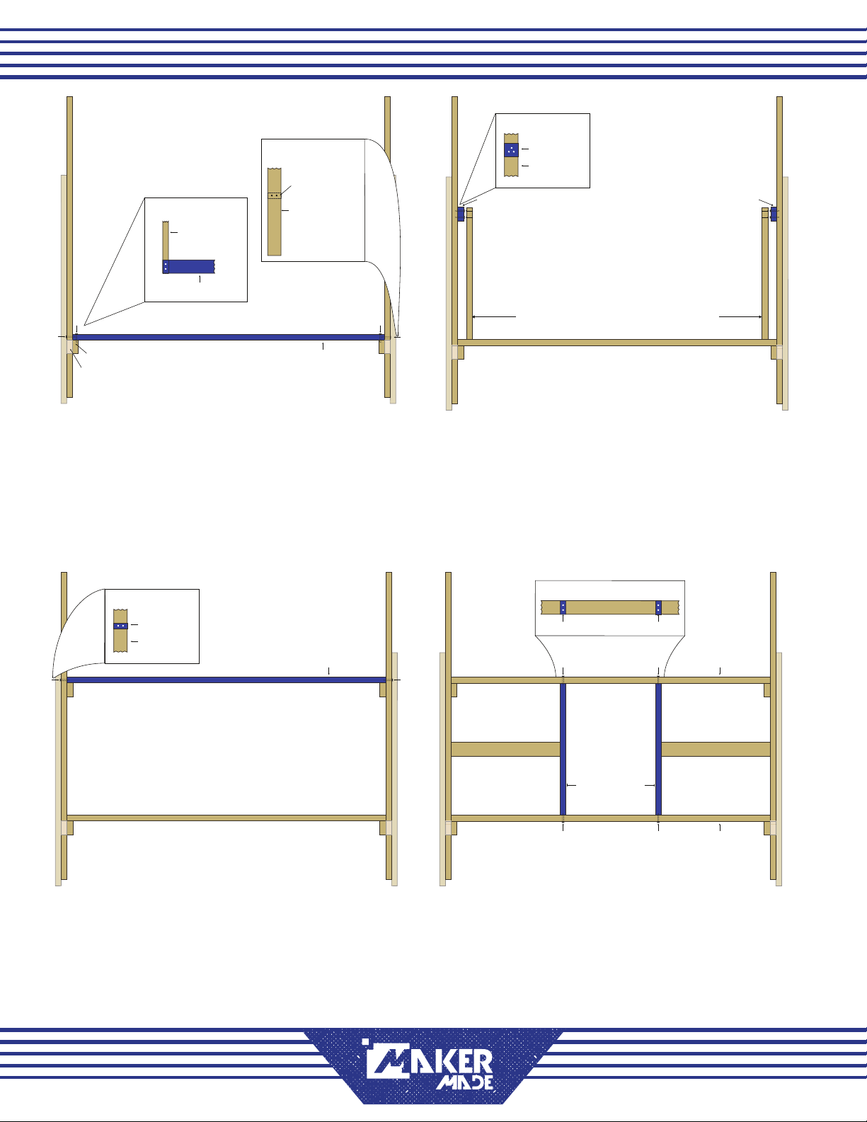
STEP 5A ATTACH LOWER FRONT CROSSMEMBER
•Rest lower front crossmember on kickers
•Screw from top of crossmember into each
kicker- see Figure 1
•Screw from side of each front leg into
crossmember- see Figure 2
STEP 5C ATTACH UPPER FRONT CROSSMEMBER
•Rest upper front crossmember on spacers
•Screw through sides of front legs into
crossmember
STEP 5B ADD SPACERS
•Use verticals to measure placement of
spacers on inside of front legs
•DO NOT ATTACH VERTICALS IN THIS STEP
•Screw through spacers into front legs
STEP 6 ATTACH VERTICALS
•Use diagonals to place verticals
•DO NOT ATTACH DIAGONALS IN THIS STEP
•Screw through top crossmember into verticals
•Screw through bottom crossmember into
verticals
View from above, front
legs horizontal to oor,
back legs sticking up

BUILDING THE DEFAULT FRAME PG. 6LAST UPDATE 05.22.19
DIAGONAL 28”
DIAGONAL 28”
FRONT
CROSSMEMBER
UPPER
FRONT
CROSSMEMBER
LOWER
FRONT LEG
approx
17”
approx
18”
REAR CROSSMEMBER 88”
KICKER
SPACER
FRONT LEG
BACK LEG
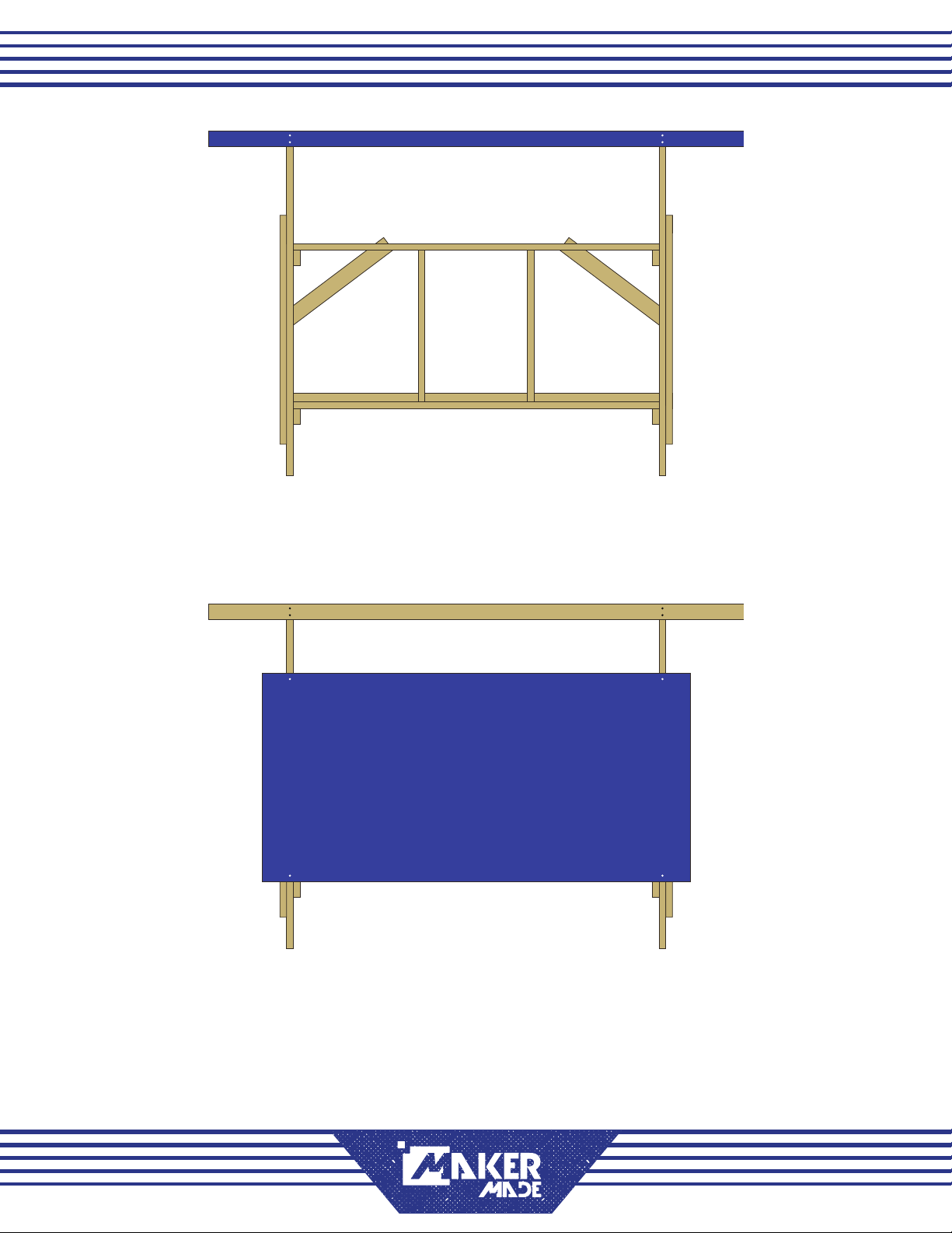
STEP 7 ATTACH DIAGONAL BRACING
•Rest diagonals with one end on front leg,
one leg on upper crossmember
•Screw diagonals in place on each end
•Placement of diagonals need not be exact
STEP 9 ATTACH SIDE BEAMS
•Beams were placed on cut list to have
one factory end, this end should face out
so top beam has a flat surface to rest on
•Place beams at 90° angles to each front leg
•Screw through beams into front legs
STEP 8 ATTACH REAR CROSSMEMBER
•Rest rear crossmember on top of kickers
where they protrude from back legs
•Screw through rear crossmember into
back legs
ALMOST FINISHED!
BUILDING THE DEFAULT FRAME PG. 7LAST UPDATE 05.22.19
TOP BEAM 120”
TOP BEAM
4’x8’ PLYWOOD SHEET
STEP 10 ATTACH TOP BEAM
•Center top beam across front
•Screw through top beam into 7” beams
on each side
STEP 11 STAND UP FRAME & ATTACH PLYWOOD
•Rest plywood on kickers
•Attach with screws through front of
plywood into each front leg
You now have a complete frame!
NEXT STEP: ATTACHING THE ELECTRONICS

THIS WORK IS LICENSED UNDER THE CREATIVE COMMONS ATTRIBUTION-SHAREALIKE 4.0 INTERNATIONAL LICENSE.
TOOLS NEEDED:
Power Drill
Screwdrivers
Safety goggles
Computer or tablet
Internet connection
BUILD TIME:
About 1 hour
MATERIALS LIST:
Part #1 AC Power Cable
Part #2 Arduino with Heat Shield
Part #4 DC Power Supply
Part #9 USB Cable
Part #10 Flash Drive (optional)
Part #11 X and Y Motor Cables
Part #12 X and Y Motor Mounts
Part #13 X and Y Motors
Hardware Bag #5
Hardware Bag #6
Before adding the electronics to the frame, there’s a bit of setup- downloading and
adding programs and information, that needs to be done
1.2: ADDING THE ELECTRONICS
DESIGN BY THE MASLOW COMMUNITY, PARTICULARLY USERS DLANG AND MADGRIZZLE
Precision Level
Difficulty Level

STEP 1: CONNECT THE MOTORS
PART #2 Arduino with Heat Shield
PART #11 X & Y Motor Cables
PART #13 X & Y Motors
•X and Y motor cables, as well as motors,
are interchangeable at this point
•Insert one end of a cable into each motor
•Insert other ends into to Ports 1 and 3 on
Arduino with yellow wire at bottom as shown
•Port 3 controls left motor Port 1 controls
right motor as viewed when facing the
Maslow CNC.
STEP 2: CONNECT THE POWER SUPPLY
PART #1 AC Power Cable
PART #3 DC Power Supply
•Plug DC power supply into shield
•Arduino also has a power supply port,
plugging power supply into it will not
damage it, but will not provide power to
motors
•Connect power cable to DC Power Supply
•Plug power cable into surge protected
electrical outlet
STEP 3: CONNECT THE USB CABLE
PART #9 USB Cable
Computer or tablet
•Plug USB cord into Arduino
•Plug other end into your computer
•USB light will come on to indicate that
board is connected and receiving power
from your computer
X
X
ATTACHING THE ELECTRONICS PG. 2LAST UPDATE 06.01.19

STEP 4: DOWNLOAD THE ARDUINO IDE
Internet connection
Computer or tablet
•In your browser, navigate to
https://www.arduino.cc/en/Main/Software
•Download latest version of Arduino IDE
•Note: Some users have reported problems
with “Windows App” version
•Open zip folder
•Install program on your computer
•Open program
STEP 6: SET UP FIRMWARE
•Click File -> Open
•Select cncctrlv1.ino
•Click Tools -> Board
•Select Arduino/Genuino Mega or Mega 2560
•Click Tools -> Port -> Your Port
•Select port- on Windows, COM3, on Mac
and Linux computers dev/tty/
•If unsure, disconnect USB cable from
Arduino, check which option disappears.
STEP 5: DOWNLOAD MASLOW FIRMWARE
•In your browser, navigate to
http://github.com/MaslowCNC/Firmware/releases/
•Download latest version of rmware
•Open zip folder
•Install program on your computer
STEP 7: ADD FIRMWARE TO ARDUINO
•Click upload button in top left corner
•This uploads rmware to Arduino
•Linux users: if getting timeout or
permissions errors, try adding username to
dialout group then logging out and back in
•When upload nishes, close Arduino IDE
STEP 8: INSTALL GROUND CONTROL
•In your browser, navigate to
https://github.com/MaslowCNC/
GroundControl/releases
•Download latest version of Ground Control
WINDOWS USERS
•Open zip folder
•Click Launch Ground Control” shortcut
MAC USERS
•Install Ground Control by moving it into
your applications folder
•Click icon in applications folder
•Select “Open”
Linux and Raspberry Pi users:
•Reference instructions online at http://
maslowcommunitygarden.org/
GroundControl.html?instructions=true
STEP 9: CONNECT GROUND CONTROL TO
MASLOW
•In Ground Control, click ACTIONS on top left
•Click PORTS, a list of ports will appear
•Select same port you used in Step 6
•Click CONNECT
THAT PART’S DONE! YOU’RE NOW READY TO
INSTALL THE ELECTRONICS ON THE FRAME.
BEFORE PROCEEDING DISCONNECT POWER
CABLES, USB CABLES, AND MOTOR CABLES.
NOTE: Ground Control is the program
which runs on your computer and lets
you control your Maslow CNC.It’s free
and is updated often.
ATTACHING THE ELECTRONICS PG. 3LAST UPDATE 06.01.19
FRONT VIEW SIDE VIEW
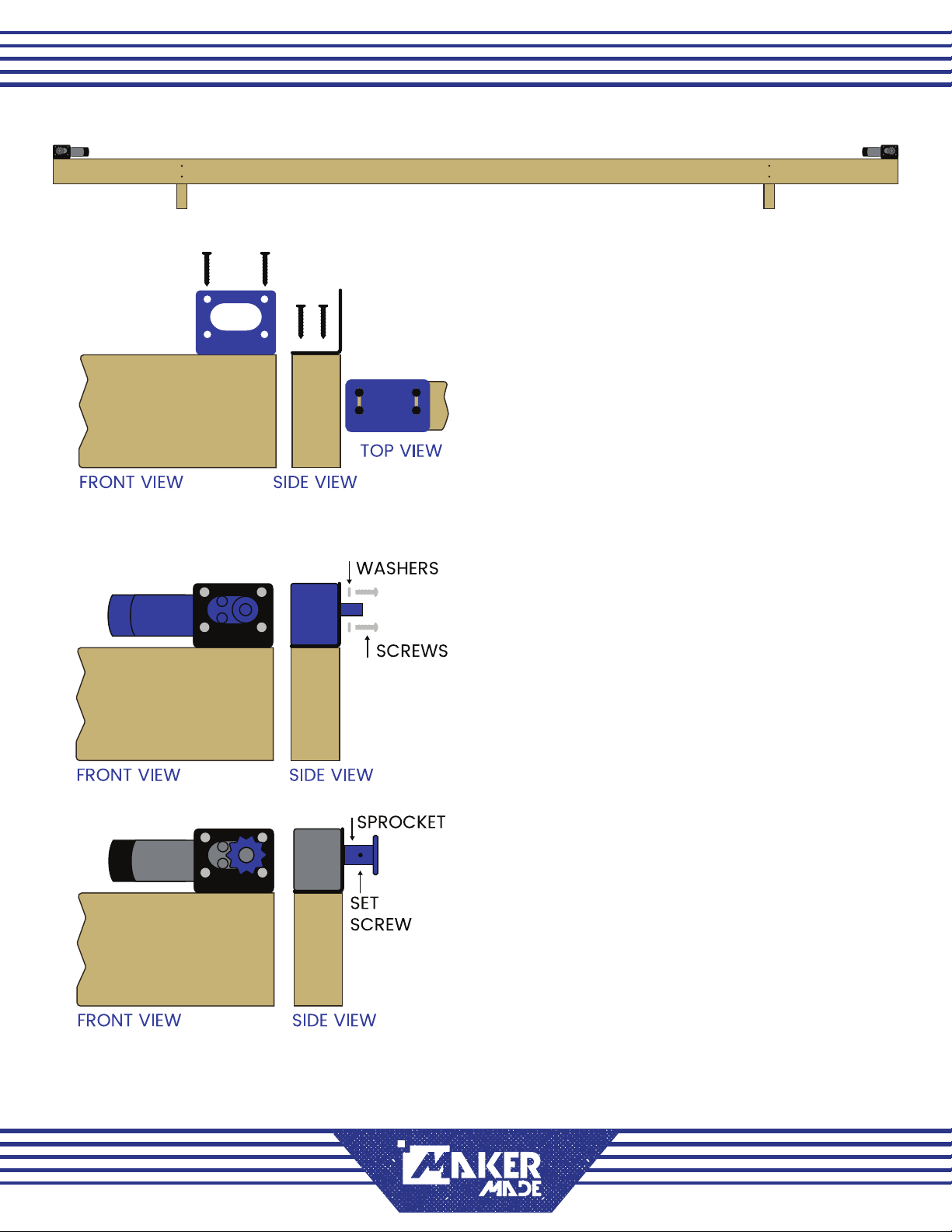
STEPS 12-14 TAKE PLACE ON THE TOP BEAM OF THE FRAME, REPEATED ON EACH END
FRONT VIEW
STEP 12: INSTALL MOTOR MOUNTS ON FRAME
BAG #4 (8) wood screws
PART #12 X/Y Motor Mounts
•Position motor mounts on beam ush with
front and side edges
•Using two screws per slot on base of each
motor mount, fasten motor mounts to
beam with wood screws
STEP 13: ATTACH MOTORS TO MOUNTS
BAG #5 (8) small screws, (8) lock washers
PART#13 X/Y Motors
•Place one motor in each bracket
•Slide lock washers over screws
•Fasten screws through front of motor
mount into aligned holes in motor
STEP 14: INSTALL SPROCKETS ON MOTOR SHAFTS
BAG#1 (2) sprockets, (2) set screws
Allen wrench
•Insert set screw in hole on side of sprocket
•Screw in slightly with allen wrench
•Place sprocket over motor shaft
•Tighten set screw with allen wrench
ATTACHING THE ELECTRONICS PG. 4LAST UPDATE 06.01.19

STEP 16 RECONNECT ELECTRONICS
PARTS #1-2 Power Cable, Power Supply
PART #9 USB Cable
PART #11 X/Y Motor Cables
•Attach Arduino to motors with cables
•Connect power supply to Arduino
•Connect USB cord to Arduino
•For more details review electronics
setup guide
USB CABLE
POWER CABLE
BACK OF FRAME
ARDUINO MOTOR & SHIELD
STEP 15 ATTACH THE ARDUINO
BAG #6 screws, standoffs
PART #2 Arduino
•Gently remove shield from Arduino
•Position Arduino in center of plywood
•Insert screws through holes
•Slide standoffs over screws
•Screw into plywood
•Re-attach shield
STEPS 15-16 TAKE PLACE ON THE BACK OF THE FRAME
ATTACHING THE ELECTRONICS PG. 5LAST UPDATE 06.01.19
NEXT STEP: BUILDING THE TEMPORARY SLED

1.3 BUILDING THE TEMPORARY SLED
TOOLS NEEDED:
Router, .25” router bit
Handsaw or Circular Saw
Phillip’s Head Screwdriver
Power Drill, .25” & .5” drill bits
Socket Wrench, various sizes
5/16 Allen Wrench
Pencil
Safety goggles
Clamps (optional)
CUT LIST:
(1) 18x18” square
(2) 1x5.5” rectangles**
MATERIALS LIST:
(1) 4x8 Plywood, .75” thick*
(2) Bricks**
(3) Size 10-32 Machine Screws
Part #5 Ring Bearings
Part #6 Ring Mount
Part #7 Ring Bracket Mounts
Part #8 Ring Carriage
Hardware Bags #3,6,7,8
*If you have scrap plywood on hand, it’s not neccesary to buy a whole sheet of plywood
**If using MakerMade metal brickholders bricks should be no more than 4.5” wide
DESIGN BY THE MASLOW COMMUNITY, PARTICULARLY USERS DLANG AND MADGRIZZLE
THIS WORK IS LICENSED UNDER THE CREATIVE COMMONS ATTRIBUTION-NONCOMMERCIAL-NODERIVATIVES 4.0 INTERNATIONAL LICENSE.
Precision Level
Difficulty Level
SLED BASE
BRICK
HOLDERS
1X5.5”
18”
18”

TEMPORARY SLED ASSEMBLY PG. 2LAST UPDATE 06.11.19
STEP 1 CUT OUT PLYWOOD PARTS
Saw, ruler
•Mark dimensions of parts on plywood
•Exactness is not critical for temporary sled
•Using hand or circular saw, cut out parts
STEP 3 REMOVE ROUTER HANDLES, BASEPLATE
5/16 allen wrench, screwdriver
•Remove cap on side of handle
•Bolt inside hole may be unscrewed with a
5/16 allen wrench
•Turn router over so baseplate is up
•Use Phillips-head screwdriver to remove 3
machine screws from bottom of baseplate
•Set router and baseplate aside
SLED BASE
BRICK
HOLDERS
1X5.5”
18”
18”
1.5” DIAMETER
NOTE: These steps are for the Rigid
router, other routers may differ
CAP BOLT
BEHIND CAP
STEP 2 CUT CENTER HOLE FOR BIT
Router, .25” router bit, pencil
•Mark 1.5”x1.5” hole in center of sled
•Use router to cut out hole, going down
approx 1/10” per pass
TOP VIEW SIDE VIEW
L-Brackets
Ring Bracket
STEP 4 ATTACH L-BRACKETS TO RING
BAG #8 (6)nuts, (6)bolts, allen wrench
PARTS #6-7 Ring bracket, (3)L-brackets
•Line up L-brackets as shown with
rectangular brackets on ring
•Insert bolts from inside of ring bracket out
through L-brackets, two per bracket
•Secure with nuts, using allen wrench to
tighten

TEMPORARY SLED ASSEMBLY PG. 3LAST UPDATE 06.11.19
Shoulder
bolt
Ring
bearing
Washer
Washer
Nut
TOP VIEW SIDE VIEW
STEP 6 MARK PLACEMENT OF COMPONENTS
Pencil
•Place components on sled as shown above
•Baseplate of router in center of sled
•Ring assembly centered around baseplate
•Bricks and holders in corners, exact
placement not critical
•Use pencil to mark 3 holes in baseplate
•Mark placement of ring and brick holders
•Mark .5” circle as shown, middle of sled,
halfway between top edge and ring
•If using Z-axis with temporary sled, leave
room for that as marked above
STEP 5 ATTACH CARRIAGES TO RING
BAG #7 (4) shoulder bolts, (4) nuts,
(8) washers, allen wrench
PART #2 Ring Bearings
PART #5 Carriage mounts
•Place one carriage on either side of ring
•Insert shoulder bolt up through bottom of
carriage, slip one washer over bolt, then
one ring bearing, then another washer
•Push shoulder bolt through top of
carriage, fasten with nut
•Do this twice for each carriage
•Use allen wrench to tighten bolts
•Bearings should still rotate freely
STEP 7 DRILL HOLES
Power drill, .25” and .5” drill bit, optional
clamps
•Place brick holders in marked spots, clamp
into place (optional but helpful)
•Mark a spot on each end of holder just
outside of where the brick will be
•Drill through holders and sled with .25” bit
•Drill 3 holes where marked for router with
.25” bit
•Drill top hole with .5” bit

TEMPORARY SLED ASSEMBLY PG. 4LAST UPDATE 06.11.19
STEP 9 ATTACH BRICKS TO SLED
Bag #3 Nuts, bolts
(2) brick holders
•Insert bolts through pre-drilled holes from
bottom of sled through to the top
•Place bricks between bolts
•Place wooden brick retainers over bolts
•Secure with nuts
STEP 10 ATTACH RING TO SLED
BAG #8 (18) small screws
•Place ring on sled centered around router
•Each L-bracket has six small holes, insert a
small screw through each hole
•Fasten with Phillips-head screwdriver
STEP 8 ATTACH ROUTER, TO SLED
(3) 10-32 machine screws
•Insert screws through pre-drilled holes
from bottom of sled into router
•Tighten with Phillips-head screwdriver
TOP VIEW SIDE VIEW
TOP VIEW SIDE VIEW
TOP VIEW SIDE VIEW
NEXT STEP: INSTALLING THE Z-AXIS

TEMPORARY SLED ASSEMBLY PG. 5LAST UPDATE 06.11.19
TERMS OF USE
This work is licensed under the
CREATIVE COMMONS
Attribution-NonCommercial-NoDerivatives
4.0 International License
To view a copy of this license
visit http://creativecommons.org/licenses/by-nc-nd/4.0/
or send a letter to
Creative Commons
PO Box 1866
Mountain View, CA 94042
YOU ARE FREE TO:
Share — copy and redistribute the material in any medium or format
The licensor cannot revoke these freedoms as long as you follow the license terms.
UNDER THE FOLLOWING TERMS:
Attribution — You must give appropriate credit, provide a link to the license, and
indicate if changes were made. You may do so in any reasonable manner, but not in
any way that suggests the licensor endorses you or your use.
NonCommercial — You may not use the material for commercial purposes.
NoDerivatives — If you remix, transform, or build upon the material, you may not
distribute the modified material.
No additional restrictions — You may not apply legal terms or technological measures
that legally restrict others from doing anything the license permits.
NOTICES:
You do not have to comply with the license for elements of the material in the public
domain or where your use is permitted by an applicable exception or limitation.
No warranties are given. The license may not give you all of the permissions necessary
for your intended use. For example, other rights such as publicity, privacy, or moral
rights may limit how you use the material.
Table of contents


