manuals.online logo
Brands
  1. Home
  2. •
  3. Brands
  4. •
  5. Triton
  6. •
  7. Wood Router
  8. •
  9. Triton RTA300 Assembly instructions

Triton RTA300 Assembly instructions

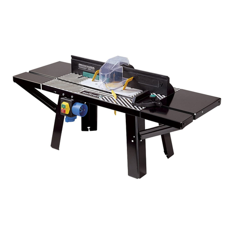
RTA300
Precision
Router Table
OPERATING & SAFETY INSTRUCTIONS
Precisiefreestafel
BEDIENINGS- EN VEILIGHEIDSINSTRUCTIES
Table Pour Défonceuse
de Précision
INSTRUCTIONS D’UTILISATION ET CONSIGNES DE SECURITE
Tisch für
Präzisionsoberfräse
BEDIENUNGS- & SICHERHEITSANWEISUNG
Banco di Precisione
per Fresatrice Verticale
ISTRUZIONI PER L’USO E LA SICUREZZA
Mesa Para Buriladora
de Precisión
INSTRUCCIONES DE FUNCIONAMIENTO Y SEGURIDAD
www.tritontools.com
2 3
GB GB
CONTENTS
SPECIFICATIONS
Part no: RTA300
Table size: 540mm x 690mm
Cuts: Planing, trenching, rebating, moulding, endgrain work,
free-hand work
Net weight: 12.5kg (27.5lb)
Protect your hearing
Always use proper hearing protection when tool noise exceeds 85dB.
Thank you for purchasing this Triton product. These instructions contain information necessary
for safe and effective operation. This product has a number of unique features,
please read this manual to make sure you get the full benefit of its unique design.
Keep this manual close to hand and ensure all users have read and fully understand the instructions.
Contents / Specifications / Symbols Parts List
PARTS LIST
Specifications 2
Symbols 2
Parts List 3
Safety 4
Fitting the Table 6
Warranty 7
1. Router table (1)
2. Vacuum hose (1)
3. Protractor (1)
Fastener Bag 1 Contents
4. Tapered hose adaptor (1)
5. Series 2000 workcentre locking hook (1)
6. M4 x 35mm countersunk screw (1)
7. M4 hex nut (1)
8. Small insert ring (1)
9. Large insert ring (1)
10. Alignment tool (1)
Router Plate Components
11. Router plate (1)
12. Sub plate (1)
Fastener Bag 2 Contents
13. Plate clamp base (4)
14. Plate clamp knob (4)
15. M6 x 45mm countersunk screw (4)
16. M6 flange nut (12)
17. M6 x 60mm coach bolt (4)
18. M6 x 16mm countersunk screw (4)
19. Plate spacer (4)
20. Washer (4)
21. Clamp (4)
22. Clamp base (4)
23. Clamp spring (4)
24. Clamp knob (4)
Sliding Table Insert Components
25. Sliding table insert (1)
Fastener Bag 3 (Sliding Table) Contents
26. Inner bearing (2)
27. Inner clamp knob (2)
28. Outer bearing (2)
29. Hold-down (1)
30. M6 x 45mm countersunk screw (2)
31. M6 x 20mm countersunk screw (3)
32. M6 flange nut (2)
33. M6 hex nut (3)
Fence Components
34. Fence (1)
35. MDF fence face (2)
36. Rear guard (1)
37. Front guard (1)
Fastener Bag 4 (Fence) Contents
38. Fence bracket (2)
39. M4 nyloc nut (10)
40. M4 x 25mm countersunk screw (2)
41. 1.5mm shim (2)
42. 1.0mm shim (2)
43. Micro adjuster (2)
44. M4 x 45mm countersunk screw (8)
45. Fence springs (8)
46. Fence spring base (4)
47. Fence spring plate (4)
Pressure Finger Components
48. Straight finger (2)
49. Bent finger (2)
50. Spacer (2)
51. Plastic washer (4)
52. Finger post (4)
SYMBOLS
ENVIRONMENTAL PROTECTION
Waste electrical products should not be
disposed of with household waste. Please
recycle where facilities exist. Check
with your local authority or retailer for
recycling advice.
Always wear ear, eye and respiratory
protection.
Instruction warning.
Do not use before viewing and
understanding the full operating
instructions
Refer to DVD for full instructions
4 5
GB GB
WARNING. Read all safety warnings
and all instructions. Failure to follow the
warnings and instructions may result in
electric shock, fire and/or serious injury.
Save all warnings and instructions for future
reference.
The term ‘power tool’ in the warnings refers
to your mains-operated (corded) power tool or
battery operated (cordless) power tool.
1. Work area safety
a. Keep work area clean and well lit. Cluttered
and dark areas invite accidents.
b. Do not operate power tools in explosive
atmospheres, such as in the presence of
flammable liquids, gases or dust. Power tools
create sparks which may ignite the dust or
fumes.
c. Keep children and bystanders away while
operating a power tool. Distractions can cause
you to lose control.
2. Electrical safety
a. Power tool plugs must match the outlet. Never
modify the plug in any way. Do not use any
adaptor plugs with earthed (grounded) power
tools. Unmodified plugs and matching outlets
will reduce risk of electric shock.
b. Avoid body contact with earthed or grounded
surfaces such as pipes, radiators, ranges
and refrigerators. There is an increased risk
of electric shock if your body is earthed or
grounded.
c. Do not expose power tools to rain or wet
conditions. Water entering a power tool will
increase the risk of electric shock.
d. Do not abuse the cord. Never use the cord for
carrying, pulling or unplugging the power tool.
Keep cord away from heat, oil, sharp edges
or moving parts. Damaged or entangled cords
increase the risk of electric shock.
e. When operating a power tool outdoors, use an
extension cord suitable for outdoor use. Use
of a cord suitable for outdoor use reduces the
risk of electric shock.
f. If operating a power tool in a damp location
is unavoidable, use a residual current device
(RCD) protected supply. Use of an RCD
reduces the risk of electric shock.
3. Personal safety
a. Stay alert, watch what you are doing and use
common sense when operating a power tool.
Do not use a power tool while you are tired
or under the influence of drugs, alcohol or
medication. A moment of inattention while
operating power tools may result in serious
personal injury.
b. Use safety equipment. Always wear eye
protection. Safety equipment such as dust
mask, non-skid safety shoes, hard hat,
or hearing protection used for appropriate
conditions will reduce personal injuries.
c. Avoid accidental starting. Ensure the switch is
in the off position before plugging in. Carrying
power tools with your finger on the switch or
plugging in power tools that have the switch
on invites accidents.
d. Remove any adjusting key or wrench before
turning the power tool on. A wrench or a key
left attached to a rotating part of the power
tool may result in personal injury.
e. Do not overreach. Keep proper footing and
balance at all times. This enables better
control of the power tool in unexpected
situations.
f. Dress appropriately. Do not wear loose clothing
or jewellery. Keep hair, clothing and gloves
away from moving parts.
g. If devices are provided for the connection of
dust extraction and collection facilities, ensure
these are connected and properly used. Use
of these devices can reduce dust related
hazards.
4. Power tool use and care
a. Do not force the power tool. Use the correct
power tool for the application. The correct
power tool will perform better and safer at the
rate for which it was designed.
b. Do not use the power tool if the switch
does not turn it on and off. Any power tool
that cannot be controlled with the switch is
dangerous and must be repaired.
c. Disconnect the plug from the power source
before making any adjustments, changing
accessories, or storing power tools. Such
preventive safety measures reduce the risk of
starting the power tool accidentally.
d. Store idle power tools out of the reach of
children and do not allow persons unfamiliar
with the power tool or these instructions
to operate the power tool. Power tools are
dangerous in the hands of untrained users.
e. Always unplug the power tool when leaving
unattended. Such preventative safety
measures reduce the risk of starting the
power tool accidentally by untrained users.
f. Maintain power tools. Check for misalignment
or binding of moving parts, breakage of parts
and any other condition that may affect the
power tools operation. If damaged, have
the power tool repaired before use. Many
accidents are caused by poorly maintained
power tools.
g. Keep cutting tools sharp and clean. Properly
maintained cutting tools with sharp cutting
edges are less likely to bind and are easier to
control.
h. Use the power tool, accessories and tool bits,
in accordance with these instructions and in
the manner intended for the particular type of
power tool, taking into account the working
conditions and the work to be performed. Use
of the power tool for operations different from
those intended could result in a hazardous
situation.
5. Service
a. Have the power tool serviced by a qualified
repair person using only identical replacement
parts. This will ensure that the safety of the
power tool is maintained.
SAFETY INSTRUCTIONS
Safety Instructions Safety Instructions
6 7
GB GB
Fitting the table
Assembly of this product is best done with the
table fitted to a workcentre or router stand.
Fitting to a Triton Series 2000 Workcentre
Fit the Series 2000
workcentre locking hook
(5) to the front tube of the
Table (1) using the M4 x
35mm countersunk screw
(6) and M4 hex nut (7).
(Fig 1)
Locate the hook into the
slot in the front end panel
of the workcentre and
lower the rear of the table
onto the bearing channels.
(Fig 2)
The router table is packed with the rear locking
catches positioned to fit the workcentre (domed
posts on the inside and catches slide toward one
another). Swing the post
ends of the latches out
toward the rear end panel,
and allow the rear of the
table to sit down flat on the
bearing channels. Secure
the rear down by swinging
the catches forward into the bearing channels.
(Fig 3)
Fitting to a Triton MK3
Workcentre
Place the Table (1) behind
the front end panel of the
workcentre and rest it on
the bearing channels. Align
the keyholes in the front
end panel of the workcentre with those in the
front tube of the router table and use the MK3
table locking pins to lock the table in position.
(Fig 4)
Secure the rear of the table down as described
above in the last paragraph of ‘Fitting to a Triton
Series 2000Workcentre’. (Fig 3)
Fitting to a Triton Router Stand
Fit the Table (1) over the front end panel of
the router stand with the conical pins locating
through the holes on the inside face of the front
tube of the table.
The rear locking latches must be reversed from
their packed position by swinging the domed
post ends of the catches outward and sliding the
catches inwards toward one another. Secure the
rear of the table down
by lowering it onto the
tabs in the rear end panel
then sliding the catches
outward to engage into
the forms
on the panel. (Fig 5)
New Model Router Stand - RSA300:
There are four hanging hooks supplied with the
new model Triton Router Stand (RSA300) which
snap onto the lower tubes of the stand. The two
wide hooks are used for storage of the router
able fence - it hangs via the scale pointer holes.
These should be fitted to the right hand side
of the stand (when viewed from the switchbox
end). The two narrow hooks are for storage of
the pressure finger assembly swhich hang via
the finger slots. These should be fitted on the
left side. This model stand also has a hole in
the rear panel for storage of the protractor (3).
For a tight fit bend the tab in the top of the hole
downward slightly.
Fitting The Table Warranty
FITTING THE TABLE
Triton Precision Power Tools guarantees
to the purchaser of this product that if
any part proves to be defective due to
faulty materials or workmanship within
12 MONTHS from the date of original
purchase, Triton will repair, or at its
discretion replace, the faulty part free of
charge.
This guarantee does not apply to
commercial use nor does it extend to
normal wear and tear or damage as a
result of accident, abuse or misuse.
* Register online within 30 days.
Terms & conditions apply.
This does not affect your statutory rights
To register your guarantee visit our web site at
www.tritontools.com* and enter your details.
Your details will be included on our mailing list
(unless indicated otherwise) for information on
future releases. Details provided will not
be made available to any third party.
PURCHASE RECORD
Date of Purchase: ___ / ___ / ____
Model: RTA300
Retain your receipt as proof of purchase
WARRANTY
FIG 1
FIG 2
FIG 4
FIG 5
FIG 3

Other manuals for RTA300

1

Other Triton Wood Router manuals

Triton TRA002 Assembly instructions

Triton

Triton TRA002 Assembly instructions

Triton TMNRTR Assembly instructions

Triton

Triton TMNRTR Assembly instructions

Triton TGA250 Assembly instructions

Triton

Triton TGA250 Assembly instructions

Triton TR205456 Quick guide

Triton

Triton TR205456 Quick guide

Popular Wood Router manuals by other brands

Carbide 3D Shapeoko 4 XXL Assembly guide

Carbide 3D

Carbide 3D Shapeoko 4 XXL Assembly guide

Professional Woodworker 46662 manual

Professional Woodworker

Professional Woodworker 46662 manual

YATO YT-82194 manual

YATO

YATO YT-82194 manual

Scheppach WRT1200 Translation of original instruction manual

Scheppach

Scheppach WRT1200 Translation of original instruction manual

Ronix 7108 manual

Ronix

Ronix 7108 manual

EINHELL Bavaria BOF 850/1 E operating instructions

EINHELL Bavaria

EINHELL Bavaria BOF 850/1 E operating instructions

Worx Professional WU600 operating instructions

Worx Professional

Worx Professional WU600 operating instructions

HIKOKI M 12V2 Handling instructions

HIKOKI

HIKOKI M 12V2 Handling instructions

Stanley FATMAX SFMCW400 Original instructions

Stanley

Stanley FATMAX SFMCW400 Original instructions

Ryobi R181D Operator's manual

Ryobi

Ryobi R181D Operator's manual

Asist AE4F120DN Instructions for use

Asist

Asist AE4F120DN Instructions for use

Challenge Xtreme PRT1204.1 Original instructions

Challenge Xtreme

Challenge Xtreme PRT1204.1 Original instructions

Parkside POF 1200 C2 Translation of the original instructions

Parkside

Parkside POF 1200 C2 Translation of the original instructions

Makita RP1803F instruction manual

Makita

Makita RP1803F instruction manual

Clarke CR4 Operation & maintenance instructions

Clarke

Clarke CR4 Operation & maintenance instructions

Bosch GTR 30 CE Professional Original instructions

Bosch

Bosch GTR 30 CE Professional Original instructions

HIKOKI M 8V2 Handling instructions

HIKOKI

HIKOKI M 8V2 Handling instructions

manuals.online logo
manuals.online logoBrands
  • About & Mission
  • Contact us
  • Privacy Policy
  • Terms and Conditions

Copyright 2025 Manuals.Online. All Rights Reserved.