MAKINEX MCP-6-SS-AU User manual

OPERATOR’S MANUAL
Rev 1021
Mobile Charge Pod (MCP)
MCP-6-SS-AU

Table of Contents
INTRODUCTION.....................................................................................................................................................1
DISCLAIMER ......................................................................................................................................................1
ABOUT THIS MANUAL.......................................................................................................................................2
SAFETY INFORMATION........................................................................................................................................3
GENERAL SAFETY INFORMATION..................................................................................................................3
GENERAL SAFETY DECAL ...............................................................................................................................5
PRODUCT SPECIFICATIONS ...............................................................................................................................6
FEATURES.........................................................................................................................................................6
OVERALL PRODUCT DIMENSIONS .................................................................................................................7
MCP SPECIFICATIONS .....................................................................................................................................7
INSTRUCTION FOR USE.......................................................................................................................................8
OPERATING MCP..............................................................................................................................................8
ASSEMBLING THE WHEELS.............................................................................................................................9
OPTIONAL: ASSEMBLING THE FORK POCKETS..........................................................................................10
USING THE CHAIN POINT...............................................................................................................................11
WALL MOUNTING............................................................................................................................................12
TIE DOWN POINTS..........................................................................................................................................13
FORK POCKETS..............................................................................................................................................14
MAINTENANCE....................................................................................................................................................15
GENERAL RECOMMENDATIONS:..................................................................................................................15
GENERAL TROUBLESHOOTING....................................................................................................................16
STORAGE.........................................................................................................................................................17
LIMITED WARRANTY..........................................................................................................................................18
WARRANTY EXCLUSIONS..............................................................................................................................19
OWNER’S RESPONSIBILITY UNDER LIMITED WARRANTY:........................................................................20
CONTACT INFORMATION ..................................................................................................................................21
APPENDICES.......................................................................................................................................................22
APPENDIX A –WIRING CIRCUIT DIAGRAM..................................................................................................22
APPENDIX B –RISK ASSESSMENT...............................................................................................................23

MCP-6-SS –User Manual Page 1 of 21
INTRODUCTION
Thank you for purchasing a MAKINEX product.
This manual provides information and procedures to safely operate and maintain the
MCP-6-SS-AU Mobile Charge Pod. For your own safety and protection from injury,
carefully read, understand, and observe the safety instructions described in this
manual.
Keep this manual or a copy of it with the product. If you lose this manual or need an
additional copy, please contact MAKINEX. This product is designed and built with user
safety in mind; however, it can present hazards if improperly operated and serviced. If
there are any questions regarding operating or servicing of this product, please contact
MAKINEX.
All rights, especially copying and distribution rights are reserved.
Copyright 2021 by MAKINEX.
No part of this publication may be reproduced in any form or by any means, electronic
or mechanical, including photocopying, without express written permission from
MAKINEX.
Any type of reproduction or distribution not authorised by MAKINEX represents an
infringement of valid copyrights and will be prosecuted. We expressly reserve the right
to make technical modifications, even without due notice, which aim at improving our
products or their safety standards.
DISCLAIMER
MAKINEX and its affiliates take no responsibility for any damage, injury or death
resulting from the incorrect or unsafe use of this product. Use of this product should be
undertaken by competent persons only. It is the operator’s responsibility to ensure that
the following safety procedures are followed. If you are unsure, do not operate this
product.
Record the model and serial numbers as well as date and place of purchase for
future reference. Have this information available when ordering parts and when making
technical or warranty inquiries.
MAKINEX SUPPORT
Refer to contact details on pg. 21
MODEL NO.
MCP-6-SS-AU
SERIAL NO.
DATE OF PURCHASE
PURCHASE LOCATION

MCP-6-SS –User Manual Page 2 of 21
ABOUT THIS MANUAL
This manual uses the following symbols to help differentiate between different kinds of
information. The safety symbol is used with a key word to alert you to potential hazards
in operating and owning power equipment. Follow all safety messages to avoid or
reduce the risk of serious injury or death.
KEY TERMS
READ
CAREFULLY
READ CAREFULLY –refers to important information that
should be paid careful attention.
CAUTION
CAUTION - indicates a potential hazardous situation which, if not
avoided, may result in minor or moderate injury
WARNING
WARNING –indicates a potentially hazardous situation which, if
not avoided, could result in death or serious injury
DANGER
DANGER –indicates an imminently hazardous situation which, if
not avoided, will result in death or serious injury
PROHIBITED
PROHIBITED –identifies actions that should never be carried out
by anyone interacting with the product.
These safety warnings do not eliminate all possible hazards that could occur therefore
it is essential to use common sense and to strictly follow any instructions to prevent
accidents.

MCP-6-SS –User Manual Page 3 of 21
SAFETY INFORMATION
GENERAL SAFETY INFORMATION
WARNING
Read this manual thoroughly before using your MCP. Failure to
follow instructions could result in serious injury or death.
WARNING
Instruct operators in care and use of the product before use!
WARNING
Keep children away from MCP at all times.
•ALWAYS ensure the applied load does not exceed the rating of the installed breaker.
•ALWAYS disconnect the MCP from mains when carrying out any maintenance.
•ALWAYS plug in the MCP BEFORE applying loads.
•ALWAYS test the RCBO’s before use.
•ALWAYS check the MCP electrical leads for damage before use.
•ALWAYS position electrical leads so that they will NOT create a tripping hazard.
•NEVER allow children or animals near the MCP.
•NEVER alter or tamper with the internal wiring of the MCP.
•NEVER operate in wet conditions.
•NEVER climb or stand on the MCP.
MCP POSITIONING FOR SAFE USE AND HANDLING
•ALWAYS leave at least a 400 mm gap between the front of the MCP door to any
surrounding building or structure to allow the doors to open.
•ALWAYS ensure the MCP is on a solid, flat surface.
•ALWAYS ensure the surrounding area is free from anything that could burn or
damage the MCP.
•ALWAYS activate the brakes when MCP is in position.
•NEVER tilt the MCP.
•NEVER attempt to lift or move the MCP without the assistance of other persons or
suitable lifting equipment.
•Keep the unit horizontal when fork or sling loading/unloading

MCP-6-SS –User Manual Page 4 of 21
ELECTRICITY RELATED SAFETY PRECAUTIONS
WARNING
RISK OF ELECTRICAL SHOCK
•Risk of electrocution
ELECTRICAL
HAZARD
•CAUTION Only charge electrical equipment in the MCP that has current test tags
according to AS/NZ 3760 and is free of any damage or misuse
•ALWAYS test the RCBOs before use.
•ALWAYS store the MCP undercover when not in use and away from damp or wet
conditions.
•ALWAYS disengage the mains power when performing any maintenance.
•NEVER try to repair electrical components if not authorised or qualified.
•NEVER use the MCP outdoor when it is raining or snowing or in wet or damp
conditions.
•NEVER use water or any other liquids to clean the unit while it is in use.
•NEVER use any damaged electrical cord sets with the MCP.
FIRE -RELATED SAFETY PRECAUTIONS
•NEVER leave any combustible materials near the MCP.

GEN –32P –User Manual Page 5 of 27
GENERAL SAFETY DECAL

GEN –32P –User Manual Page 6 of 27
PRODUCT SPECIFICATIONS
MCP:
OUTLET SOCKETS
6 X Dual 2-Pole 10A Outlets
RCBO
16A Type A 30mA 2-Pole
SUPPLY LEAD
2.5mm23-Core Flex Cable with 15A 3-Pin Plug
BODY MATERIAL
Fire Rated UL 94 V-2 HDPE
DRY WEIGHT (kg/lbs)
74/163
BODY DIMENSIONS
(L X D X H) mm (in)
1480 x 430 x 1371
LOCKER DIMENSIONS
(L X D X H) mm (in)
Dimensions at rear of locker
545 (21.5) x 300 (11.8) x 370 (14.6)
Dimensions at front of locker
580 (22.8) x 330 (13.0) x 370 (14.6)
This product complies with AS/NZS 3190 and AS/NZS 3012 as a Portable Socket Outlet
Assembly (PSOA). Suitable for construction sites.
FEATURES
FEATURES
Durable rotation moulded body
Four swivel wheels with brakes for easy manoeuvrability
Complies with AS/NZS 3190, AS/NZS 3012 and Fire Rating UL 94 V-2
IP 33 rated against dust and water ingress
Lifting point for transportation
Secure lock-up for charging valuable site equipment

MCP-6-SS –User Manual Page 7 of 21
OVERALL PRODUCT DIMENSIONS
MCP SPECIFICATIONS
Dimensions in mm

MCP-6-SS –User Manual Page 8 of 21
INSTRUCTION FOR USE
WARNING
Read and adhere to all safety and operation instructions.
OPERATING MCP
CAUTION
Always have the brakes engaged while it is stationary.
POWERING THE MCP
1. Remove all loads from the Dual 10A outlets.
2. Ensuring the mains power switch (if fitted) is in the ‘off’ position, unwind the electrical
cable on top of the unit and connect it to the mains socket. Make sure no trip hazard
is created from the cable.
3. Turn the mains switch to the ‘on’ position.
4. Ensure the breaker on the MCP is in the ‘on’ position (contact a qualified electrician
if in the ‘off’ position).
5. The MCP now has power.
OPENING THE LOCKERS
The MCP comes with six (6) independent padlock-able lockers for storage-during-charging
of electrical site equipment.
1. Place the charging equipment in the locker while feeding the electrical lead towards
the centre of the MCP so it rests inside the cut-out between where the door closes
and the body. Make sure the testing tag is left outside the locker for easy inspection.
2. After making sure the keys have not been left in the locker, close thedoor and replace
the padlock.
CONNECTING ELECTRICAL DEVICES
The MCP can supply 230V AC through six (6) dual 10 amp double pole outlets.
1. Connect the appliance to the corresponding GPO.
2. Set the switch on the outlet to the ‘on’ position.
Note: Only charge electrical equipment in the MCP that has current test tags according to
AS/NZ 3760 and is free of any damage or misuse
SHUTTING DOWN THE MCP
1. Turn all switches on the outlets to the ‘off’ position.
2. Turn the mains switch (if fitted) to the ‘off’ position, otherwise unplug from mains.
MCP-6-SS –User Manual Page 9 of 21
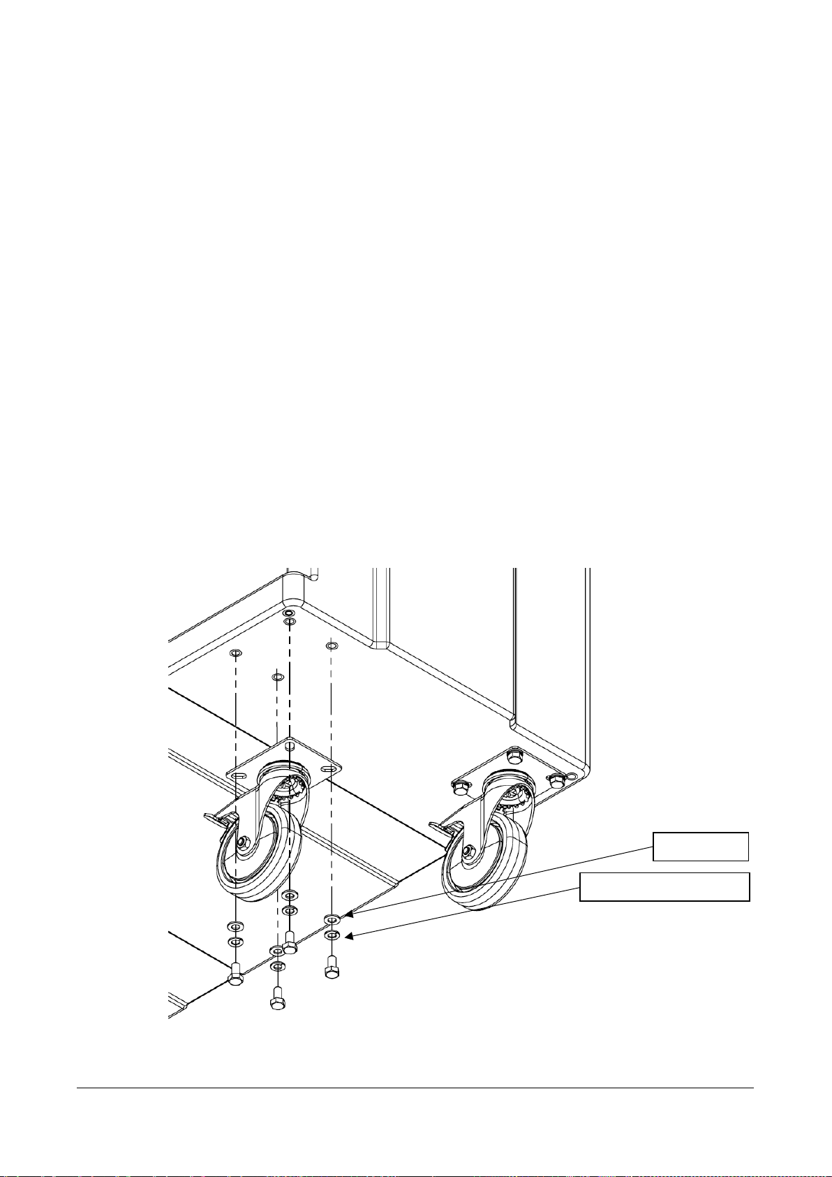
ASSEMBLING THE WHEELS
The wheels for the MCP, which you will find in one of the lockers, come pre-packaged with
all required fasteners for assembly. Included in the package should be:
- 16 x M8x16 mm Hex Bolt
- 16 x M8 Washer
- 16 x M8 Spring Washer
The tools required for the install are:
- Ratchet or 13 mm Spanner
- 13 mm Socket to suit ratchet
To install the wheels:
1. Open the packaging containing the wheels and the fasteners
2. Each wheel will require four (4) M8x16 mm Hex Bolts, four (4) M8 Washers, and four
(4) M8 Spring Washers.
3. As seen in the image below, fit a spring washer and washer, respectively, to the M8
bolt before passing it through the hole in the wheel and screwing it into the body.
4. Repeat steps 1-3 for each of the four boltholes on each of the four wheels, ensuring
that the matching castors are fastened on the same short end of the body.
SPRING WASHER
WASHER

MCP-6-SS –User Manual Page 10 of 21
OPTIONAL: ASSEMBLING THE FORK POCKETS
The fork pockets for the MCP, which you will find in one of the lockers, come pre-packaged
with all required fasteners for assembly. Included in the package should be:
- 8 x M8x16 mm Hex Bolt
- 8 x M8 Washer
- 8 x M8 Spring Washer
The tools required for the install are:
- Ratchet or 13 mm Spanner
- 13 mm Socket to suit ratchet
To install the fork pockets:
1. Open the packaging containing the fork pockets and the fasteners
2. Each fork pocket will require four (4) M8x16 mm Hex Bolts, four (4) M8 Washers, and
four (4) M8 Spring Washers.
3. As seen in the image below, fit a spring washer and washer, respectively, to the M8
bolt before passing it through the hole in the fork pocket and screwing it into the body.
4. Repeat steps 1-3 for each of the four boltholes on each of the fork pockets.
SPRING WASHER
WASHER

MCP-6-SS –User Manual Page 11 of 21
USING THE CHAIN POINT
The rear of the MCP is designed such that a chain or other similar load-bearing device can
be passed in and out of the openings on the back of the unit as pictured below. This is to
allow the user to secure the MCP in place and prevent it unintentionally moving out of place.

MCP-6-SS –User Manual Page 12 of 21
WALL MOUNTING
The MCP has eight (8) x 9 mm diameter wall mounting through holes on the rear of
the body which can be used instead of, or in addition to, positioning the unit in place
using the wheel brakes. When installing the unit in a wall mount setting, a spacer must
be placed between the back of the unit and the wall. This is to allow the ventilation
holes to remain unobstructed. The illustration below shows the method of installation.
Prior to mounting the unit, holes must be drilled to the appropriate size in the wall to
receive the fasteners used to wall mount the unit. A typical M8 bolt will fit through the
holes. Be sure to use the appropriate bolts depending on what surface the unit is being
mounted to e.g. masonry, steel, wood fasteners etc., etc.
MCP-6-SS –User Manual Page 13 of 21
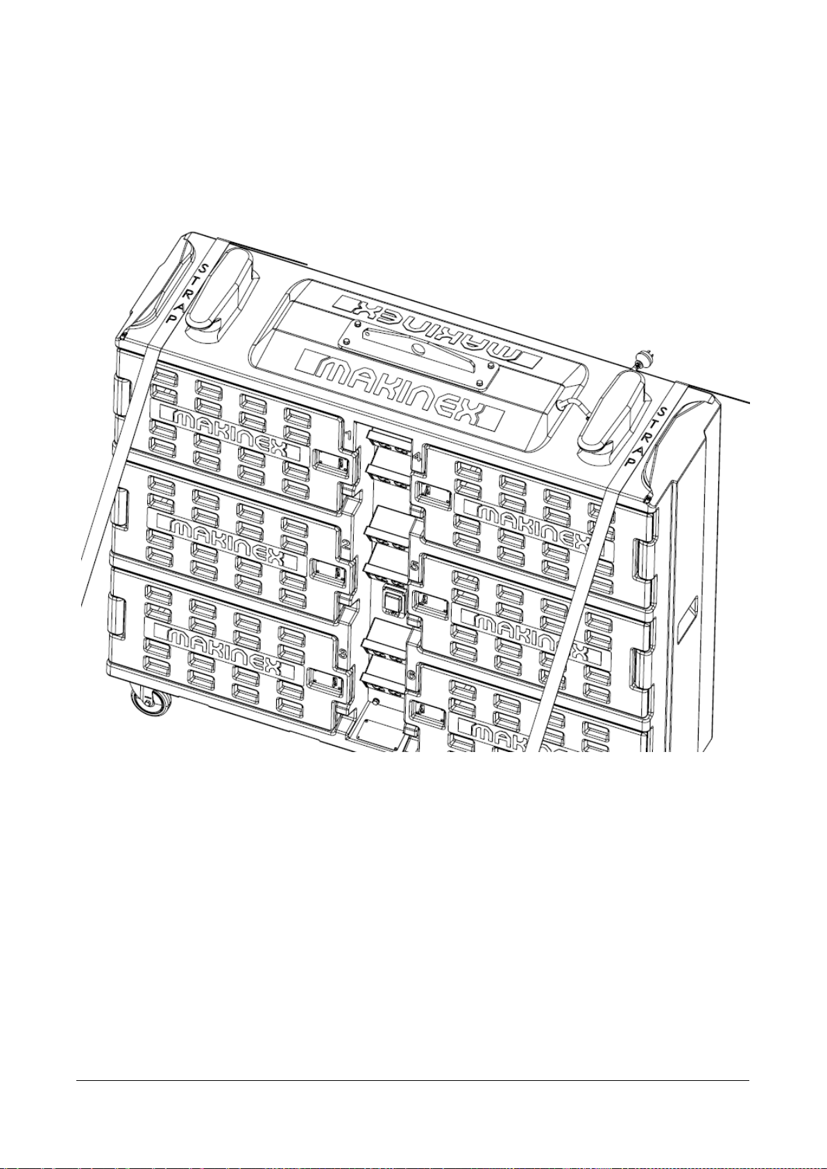
TIE DOWN POINTS
The MCP tie down points can be found at the top of the unit inbetween the cable cleats
and short edge of the top of the unit. These tie down instructions are only applicable
for when the MCP is in the upright position with all 4 castor wheel brakes engaged.
The image below demonstrates how the tie down point should be used.
MCP-6-SS –User Manual Page 14 of 21
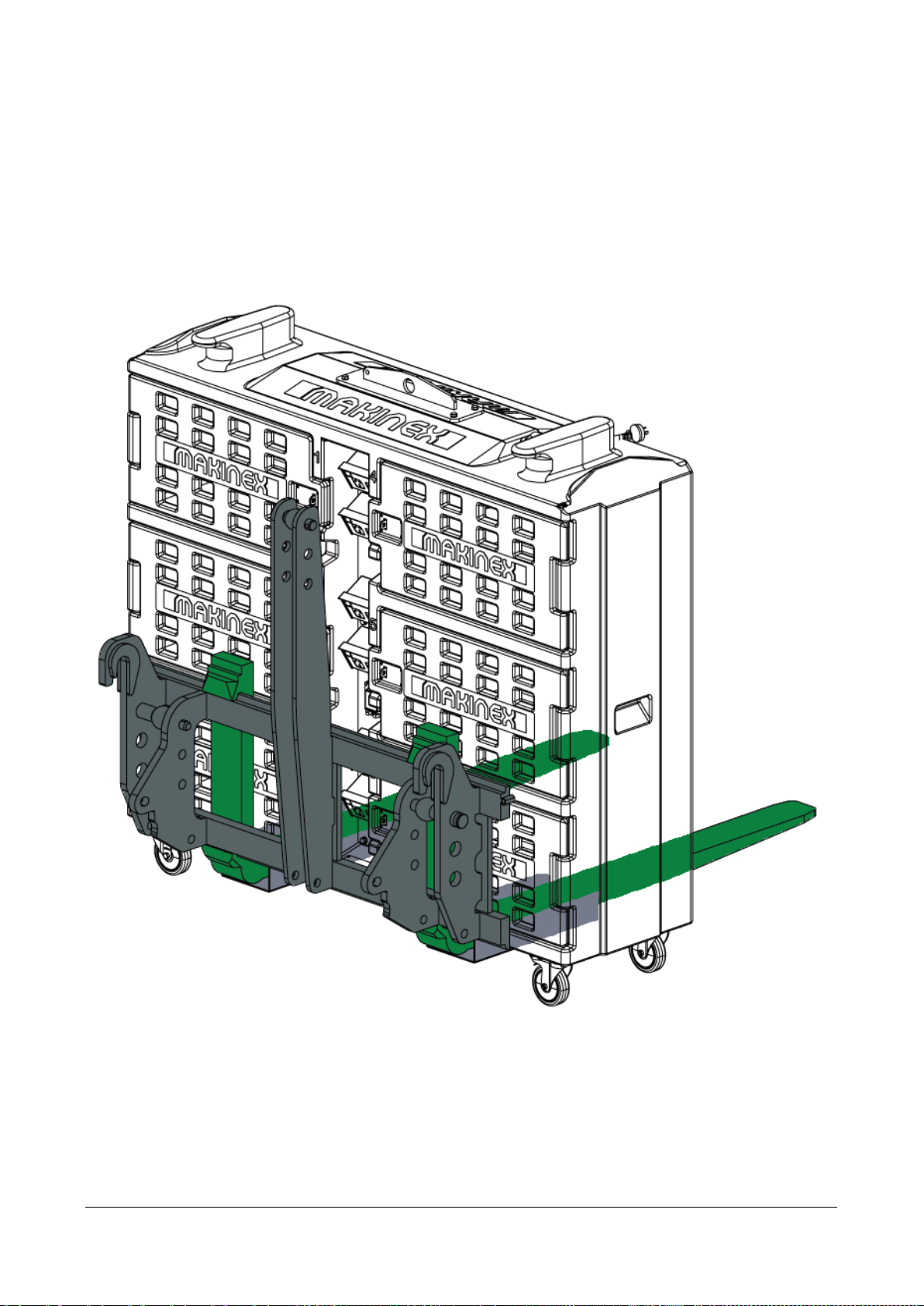
FORK POCKETS
The MCP comes fitted with forklift pockets which allow the unit to be safely moved with a
forklift or similar machinery / equipment. When using the fork pockets, where possible,
ensure the MCP is pushed up against the head board or similar support of the fork lift / lifting
equipment. This will ensure the most stability during movement and minimize risk of injury.
The transparent image below demonstrates how the MCP may be positioned on the tines of
a forklift.

MCP-6-SS –User Manual Page 15 of 21
MAINTENANCE
GENERAL RECOMMENDATIONS:
Regular maintenance will extend the life of the MCP.
The MCP’s warranty does not cover items that have been subjected to operator abuse
or negligence. To receive full value from the warranty, the operator must maintain the
MCP as instructed in this manual, including proper storage and appropriate servicing.
Should you have questions about replacing components on your MCP, please contact
dealer for assistance. MAKINEX dealers have access to all the special tools, technical
information, parts and training required to maintain your MAKINEX product in peak
operating condition.
GENERAL MCP CHECKS
It is good practise to check the MCP before and after use, looking at:
•Electrical leads
•Condition of RCBO
•General purpose outlets are not damaged
•Condition of mains plugs
•Castor wheel condition
•Water damage
•Any possible leaks

MCP-6-SS –User Manual Page 16 of 21
GENERAL TROUBLESHOOTING
PROBLEM
POSSIBLE CAUSES
CORRECTIONS
MCP WILL NOT
PROVIDE POWER
Damaged electrical lead
Contact qualified electrician
Mains switch is in ‘off’ position
Turn mains switch to ‘on’ position
RCBO is in ‘off’ position
Contact qualified electrician
Outlet switch is in ‘off’ position
Turn outlet switch to ‘on’ position
Equipment faulty
Inspect the condition of equipment
being charged.
MCP WILL NOT
MOVE
Brake is applied
Turn brakes to ‘off’ position on all
wheels
Damaged castor wheel
Contact dealer for replacement
Castor wheel is clogged
Inspect wheel for debris and
remove if possible
Uneven terrain
Inspect surface for any obstructions
UNIDENTIFIED
Contact authorised Makinex dealer for assistance.
For other problems or further instructions, contact your authorised Makinex dealer.

MCP-6-SS –User Manual Page 17 of 21
STORAGE
STORAGE OF MCP
To prolong the longevity of the MCP, it is best practice to store the MCP in a dry place,
away from exposure to the weather. To keep the MCP in good working order, ensure:
1. Storage is in a dry place, sheltered from the elements of the weather.
2. Between uses, wipe down any surfaces which are especially dirty or covered in foreign
debris.

MCP-6-SS –User Manual Page 18 of 21
LIMITED WARRANTY
To take advantage of the MAKINEX limited warranty, you must have maintenance
performed according to the maintenance schedule by an authorised MAKINEX dealer
or MAKINEX service technician. You are free to have your MAKINEX product serviced
by any suitably qualified mechanic or electrician (depending on the mechanical or
electrical requirement) and this will not affect your statutory warranties, however, failure
by the owner to have the recommended servicing carried out by an authorised
MAKINEX dealer/service technician means that you cannot take advantage of the
MAKINEX limited warranty.
MAKINEX warrants each new MCP to be free from defects in material and
workmanship under normal domestic and industrial use and service for the period
specified below, conditional to the limitations and exclusions printed on this page. This
warranty applies only to new MAKINEX product distributed by us and by our authorised
MAKINEX dealers.
Under the limited warranty and at MAKINEX’s discretion, upon evaluation, inspection
and testing by a MAKINEX dealer or a MAKINEX service technician, MAKINEX will
repair and replace of defective part(s).
AUSTRALIA: Our goods come with guarantees that cannot be excluded under the
Australian Consumer Law.
WARRANTY: (Ex-factory/ Reseller premise)
MAKINEX warrants to the original purchaser:
•Frame and all Electrical components will be free of defects in material and
workmanship for a period of one year from the original date of purchase.
Table of contents
Other MAKINEX Batteries Charger manuals

Popular Batteries Charger manuals by other brands

Targus
Targus APA110US quick start

XS Power
XS Power HF1215 user guide
Gokhale Method Enterprise
Gokhale Method Enterprise Gokhale Posture Tracker Wireless Charger user manual

Bosch
Bosch GAL 1830 W Professional Original instructions

Tool it
Tool it GYSPACK 400 AIR manual

Hama
Hama 00054176 operating instructions


