Makita DUC254 User manual

DUC204
DUC254
DUC254C
EN Cordless Chain Saw INSTRUCTION MANUAL 8
PL Akumulatorowa Pilarka
Łańcuchowa INSTRUKCJA OBSŁUGI 20
HU Akkumulátoros láncfűrész HASZNÁLATI KÉZIKÖNYV 33
SK Akumulátorová reťazová píla NÁVOD NA OBSLUHU 46
CS Akumulátorová řetězová pila NÁVOD K OBSLUZE 58
UK Бездротова ланцюгова
пила ІНСТРУКЦІЯ З
ЕКСПЛУАТАЦІЇ 70
RO Ferăstrău cu lanț cu
acumulator MANUAL DE INSTRUCŢIUNI 85
DE Akku-Kettensäge BETRIEBSANLEITUNG 98

Fig.1
12 34
5
6
12
13
14
7
8
10
9
11
16
17
18
15
Fig.2
1
2
3
Fig.3
1
2
Fig.4
2

1
2
Fig.5
1
2
Fig.6
1
23
23
Fig.7
1
Fig.8
12
Fig.9
1
2
Fig.10
2
3
4
1
Fig.11
3

1
Fig.12
1
Fig.13
1
2
3
Fig.14
1
Fig.15
12
Fig.16
1
2
Fig.17
Fig.18
Fig.19
4

Fig.20
1
2
Fig.21
Fig.22
Fig.23
Fig.24
A
B
A
B
Fig.25
1
2
Fig.26
22
11
31
Fig.27
5

30
30
55 55
Fig.28
1
2
Fig.29
30
1/5
1
Fig.30
Fig.31
Fig.32
Fig.33
1
2
Fig.34
1
2
Fig.35
6

1
2
Fig.36
7

8ENGLISH
ENGLISH (Original instructions)
SPECIFICATIONS
Model: DUC204 DUC254 DUC254C
Overall length (without guide bar) 256 mm
Rated voltage D.C. 18 V
Net weight 2.8 - 3.3 kg
Standard guide bar length 200 mm 250 mm
Recommended guide bar length
with 90PX 200 - 250 mm -
with 91PX -250 mm -
with 25AP -250 mm
Applicable saw chain type
(refer to the table below)
90PX 90PX
91PX
25AP
Standard sprocket Number of teeth 6 9
Pitch 3/8″ 1/4″
Chain speed 0 - 24 m/s
(0 - 1,440 m/min)
0 - 22.5 m/s
(0 - 1,350 m/min)
Chain oil tank volume 140 cm3
• Duetoourcontinuingprogramofresearchanddevelopment,thespecicationshereinaresubjecttochange
without notice.
• Specicationsmaydifferfromcountrytocountry.
• The weight may differ depending on the attachment(s), including the battery cartridge. The lightest and heavi-
est combination, according to EPTA-Procedure 01/2014, are shown in the table.
Applicable battery cartridge
BL1815N / BL1820 / BL1820B / BL1830 / BL1830B / BL1840 / BL1840B / BL1850 / BL1850B / BL1860B
• Some of the battery cartridges listed above may not be available depending on your region of residence.
WARNING: Only use the battery cartridges listed above. Use of any other battery cartridges may cause
injuryand/orre.
Saw chain, guide bar, and sprocket combination
Saw chain type 90PX
Number of drive links 33 40
Guide bar Guide bar length 200 mm 250 mm
Cutting length 180 mm 244 mm
Pitch 3/8″
Gauge 1.1 mm
Type Sprocket nose bar
Sprocket Number of teeth 6
Pitch 3/8″
Saw chain type 91PX
Number of drive links 40
Guide bar Guide bar length 250 mm
Cutting length 244 mm
Pitch 3/8″
Gauge 1.3 mm
Type Sprocket nose bar
Sprocket Number of teeth 6
Pitch 3/8″

9ENGLISH
Saw chain type 25AP
Number of drive links 60
Guide bar Guide bar length 250 mm
Cutting length 250 mm
Pitch 1/4″
Gauge 1.3 mm
Type Carving bar
Sprocket Number of teeth 9
Pitch 1/4″
NOTICE: When using 25AP saw chain, use with Sprocket 9 (optional accessory).
WARNING:Useappropriatecombinationoftheguidebarandsawchain.Otherwisepersonalinjurymay
result.
Symbols
The following show the symbols used for the equipment.
Be sure that you understand their meaning before use.
Read instruction manual.
Wear safety glasses.
Wear ear protection.
Wear a helmet, goggles and ear protection.
Use appropriate protection for foot-leg and
hand-arm.
This saw is to be used by properly trained
operators only.
Do not expose to moisture.
Maximum permissible cut length
Always use two hands when operating the
chain saw.
Direction of chain travel
Sawchainoiladjustment
Ni-MH
Li-ion
Only for EU countries
Do not dispose of electric equipment or battery
pack together with household waste material!
In observance of the European Directives,
on Waste Electric and Electronic
Equipment and Batteries and Accumulators
and Waste Batteries and Accumulators
and their implementation in accordance
with national laws, electric equipment and
batteries and battery pack(s) that have
reached the end of their life must be col-
lected separately and returned to an envi-
ronmentally compatible recycling facility.
Intended use
The tool is intended for cutting branches and pruning
trees. It is also suitable for tree service.
Noise
The typical A-weighted noise level determined accord-
ing to IEC62841-4-1:
Model DUC204
Sound pressure level (LpA) : 92.2 dB(A)
Sound power level (LWA) : 103.2 dB (A)
Uncertainty (K) : 2.5 dB(A)
Model DUC254
Sound pressure level (LpA) : 92.2 dB(A)
Sound power level (LWA) : 103.2 dB (A)
Uncertainty (K) : 2.5 dB(A)
Model DUC254C
Sound pressure level (LpA) : 92.2 dB(A)
Sound power level (LWA) : 103.2 dB (A)
Uncertainty (K) : 2.5 dB(A)
WARNING: Wear ear protection.
Vibration
The vibration total value (tri-axial vector sum) deter-
mined according to IEC62841-4-1:
Model DUC204
Work mode: cutting wood
Vibration emission (ah,W) : 3.1 m/s2
Uncertainty (K) : 1.5 m/s2
Model DUC254
Work mode: cutting wood
Vibration emission (ah,W) : 3.1 m/s2
Uncertainty (K) : 1.5 m/s2
Model DUC254C
Work mode: cutting wood
Vibration emission (ah,W) : 4.1 m/s2
Uncertainty (K) : 1.5 m/s2
NOTE:
The declared vibration emission value has been
measured in accordance with the standard test method
and may be used for comparing one tool with another.
NOTE:
The declared vibration emission value may
also be used in a preliminary assessment of exposure.

10 ENGLISH
WARNING: The vibration emission during actual
use of the power tool can differ from the declared
emission value depending on the ways in which the
tool is used.
WARNING: Be sure to identify safety measures
to protect the operator that are based on an estima-
tion of exposure in the actual conditions of use (taking
account of all parts of the operating cycle such as
the times when the tool is switched off and when it is
running idle in addition to the trigger time).
EC Declaration of Conformity
For European countries only
The EC declaration of conformity is included as Annex A
to this instruction manual.
SAFETY WARNINGS
General power tool safety warnings
WARNING: Read all safety warnings, instruc-
tions, illustrations and specications provided
with this power tool. Failure to follow all instructions
listedbelowmayresultinelectricshock,reand/or
seriousinjury.
Save all warnings and instruc-
tions for future reference.
The term "power tool" in the warnings refers to your
mains-operated (corded) power tool or battery-operated
(cordless) power tool.
Cordless Chain saw safety warnings
1. Keep all parts of the body away from the saw
chain when the chain saw is operating. Before
you start the chain saw, make sure the saw
chain is not contacting anything. A moment of
inattention while operating chain saws may cause
entanglement of your clothing or body with the
saw chain.
2. Always hold the chain saw with your right
hand on the top handle and your left hand on
the front handle. Holding the chain saw with a
reversedhandcongurationincreasestheriskof
personalinjuryandshouldneverbedone.
3. Hold the power tool by insulated gripping
surfaces only, because the saw chain may con-
tact hidden wiring. Saw chains contacting a "live"
wire may make exposed metal parts of the power
tool "live" and could give the operator an electric
shock.
4. Wear safety glasses and hearing protection.
Further protective equipment for head, hands,
legs and feet is recommended. Adequate protec-
tiveclothingwillreducepersonalinjurybyying
debris or accidental contact with the saw chain.
5. Always keep proper footing.
6. When cutting a limb that is under tension be
alert for spring back. When the tension in the
woodbresisreleasedthespringloadedlimbmay
strike the operator and/or throw the chain saw out
of control.
7.
Use extreme caution when cutting brush and sap-
lings. The slender material may catch the saw chain
and be whipped toward you or pull you off balance.
8. Carry the chain saw by the front handle with
the chain saw switched off and away from your
body. When transporting or storing the chain
saw always t the guide bar cover. Proper
handling of the chain saw will reduce the likelihood
of accidental contact with the moving saw chain.
9. Follow instructions for lubricating, chain ten-
sioning and changing accessories. Improperly
tensioned or lubricated chain may either break or
increase the chance for kickback.
10. Keep handles dry, clean, and free from oil and
grease. Greasy, oily handles are slippery causing
loss of control.
11. Cut wood only. Do not use chain saw for pur-
poses not intended. For example: do not use
chain saw for cutting plastic, masonry or non-
wood building materials. Use of the chain saw for
operations different than intended could result in a
hazardous situation.
12. Causes and operator prevention of kickback:
Kickback may occur when the nose or tip of the
guidebartouchesanobject,orwhenthewood
closes in and pinches the saw chain in the cut.
Tip contact in some cases may cause a sudden
reverse reaction, kicking the guide bar up and
back towards the operator. Pinching the saw chain
along the top of the guide bar may push the guide
bar rapidly back towards the operator. Either of
these reactions may cause you to lose control of
the saw which could result in serious personal
injury.Donotrelyexclusivelyuponthesafety
devices built into your saw. As a chain saw user,
you should take several steps to keep your cutting
jobsfreefromaccidentorinjury.
Kickback is the result of tool misuse and/or incor-
rect operating procedures or conditions and can be
avoided by taking proper precautions as given below:
• Maintainarmgrip,withthumbsandngers
encircling the chain saw handles, with both
hands on the saw and position your body
and arm to allow you to resist kickback
forces. Kickback forces can be controlled by
the operator, if proper precautions are taken.
Do not let go of the chain saw.
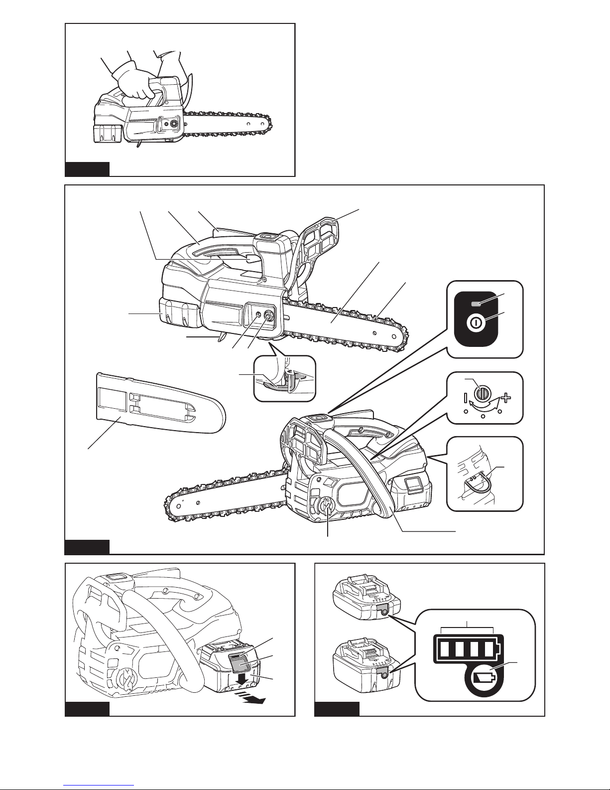
►Fig.1
• Do not overreach and do not cut above
shoulder height. This helps prevent unin-
tended tip contact and enables better control
of the chain saw in unexpected situations.
• Only use replacement bars and chains spec-
iedbythemanufacturer.Incorrectreplace-
ment bars and chains may cause chain
breakage and/or kickback.
• Follow the manufacturer’s sharpening and
maintenance instructions for the saw chain.
Decreasing the depth gauge height can lead
to increased kickback.

11 ENGLISH
13. Before starting work, check that the chain
saw is in proper working order and that its
condition complies with the safety regulations.
Check in particular that:
• The chain brake is working properly;
• The run-down brake is working properly;
• Thebarandthesprocketcoveraretted
correctly;
• The chain has been sharpened and ten-
sioned in accordance with the regulations.
14. Do not start the chain saw with the chain cover
being installed on it. Starting the chain saw with
the chain cover being installed on it may cause
the chain cover to thrown out forward resulting in
personalinjuryanddamagetoobjectsaroundthe
operator.
Top handle chainsaw specic safety
warnings
1. This chain saw is designed especially for tree
care and surgery. The chain saw is intended
to be used by properly trained persons only.
Observe all instructions, procedures and rec-
ommendations from the relevant professional
organization. Otherwise fatal accidents may
occur. It is recommend that always using a
rising platform (cherry picker, lift) for sawing
in trees. Rappelling techniques are extremely
dangerous and require special training. The
operators must be trained to become familiar
with safety equipment usage and climbing
techniques. Always use the appropriate belts,
ropes and carabiners when working in trees.
Always use restraining equipment for both the
operator and the saw.
2. Perform cleaning and maintenance before
storage in accordance with the instruction
manual.
3. Ensure safe positioning of the chain saw
during car transportation to avoid fuel or chain
oil leakage, damage to the tool and personal
injury.
4. Regularly check the functionality of chain
brake.
5. Do not ll the chain oil near re. Never smoke
when you ll the chain oil.
6. National regulation may restrict the use of the
chain saw.
7. If the equipment gets heavy impact or fall,
check the condition before continuing work.
Check the controls and safety devices for mal-
function. If there is any damage or doubt, ask
our authorized service center for the inspec-
tion and repair.
8. Always activate the chain brake before starting
the chain saw.
9. Hold the saw rmly in place to avoid skating
(skid movement) or bouncing of the saw when
starting a cut.
10. At the end of the cut, be careful to keep your
balance due to the “drop”.
11. Take into account the direction and speed of
the wind. Avoid sawdust and chain oil mist.
Protective equipment
1. In order to avoid head, eye, hand or foot
injuries as well as to protect your hearing the
following protective equipment must be used
during operation of the chain saw:
—
The kind of clothing should be appropriate, i. e.
itshouldbetight-ttingbutnotbeahindrance.
Donotwearjewelryorclothingwhichcould
become entangled with bushes or shrubs. If
you have long hair, always wear a hairnet!
— It is necessary to wear a protective helmet
whenever working with the chain saw. The
protective helmet is to be checked in regu-
lar intervals for damage and is to be replaced
after 5 years at the latest. Use only approved
protective helmets.
— The face shield of the protective helmet (or
the goggles) protects against sawdust and
wood chips. During operation of the chain
saw always wear a goggle or a face shield to
preventeyeinjuries.
— Wear adequate noise protection equip-
ment (ear muffs, ear plugs, etc.)
— The protective jacket consists of 22 layers
of nylon and protects the operator against
cuts. It is always to be worn when working
from elevated platforms (cherry pickers,
lifts), from platforms mounted on ladders or
when climbing with ropes.
— The protective brace and bib overall is
made of a nylon fabric with 22 layers and
protects against cuts. We strongly recom-
mend its use.
—
Protective gloves made of thick leather are part
of the prescribed equipment and must always be
worn during operation of the chain saw.
— During operation of the chain saw safety
shoes or safety bootsttedwithantiskid
sole, steel toe caps and protection for the
leg must always to be worn. Safety shoes
equipped with a protective layer provide
protection against cuts and ensure a secure
footing. For working in trees the safety boots
must be suitable for climbing techniques.
Vibration
1. Individuals with poor circulation who are exposed
toexcessivevibrationmayexperienceinjuryto
blood vessels or the nervous system. Vibration
may cause the following symptoms to occur in the
ngers,handsorwrists:“Fallingasleep”(numb-
ness), tingling, pain, stabbing sensation, alteration
of skin colour or of the skin. If any of these symp-
toms occur, see a physician! To reduce the risk
of“whitengerdisease”,keepyourhandswarm
during operation and well maintain the equipment
and accessories.
SAVE THESE INSTRUCTIONS.
WARNING: DO NOT let comfort or familiarity
with product (gained from repeated use) replace
strict adherence to safety rules for the subject
product. MISUSE or failure to follow the safety
rules stated in this instruction manual may cause
serious personal injury.

12 ENGLISH
Important safety instructions for
battery cartridge
1. Before using battery cartridge, read all instruc-
tions and cautionary markings on (1) battery
charger, (2) battery, and (3) product using
battery.
2. Do not disassemble battery cartridge.
3. If operating time has become excessively
shorter, stop operating immediately. It may
result in a risk of overheating, possible burns
and even an explosion.
4. If electrolyte gets into your eyes, rinse them
out with clear water and seek medical atten-
tion right away. It may result in loss of your
eyesight.
5. Do not short the battery cartridge:
(1) Do not touch the terminals with any con-
ductive material.
(2) Avoid storing battery cartridge in a con-
tainer with other metal objects such as
nails, coins, etc.
(3) Do not expose battery cartridge to water
or rain.
A battery short can cause a large current
ow, overheating, possible burns and even a
breakdown.
6. Do not store the tool and battery cartridge in
locations where the temperature may reach or
exceed 50 °C (122 °F).
7. Do not incinerate the battery cartridge even if
it is severely damaged or is completely worn
out. The battery cartridge can explode in a re.
8. Be careful not to drop or strike battery.
9. Do not use a damaged battery.
10. The contained lithium-ion batteries are subject
to the Dangerous Goods Legislation require-
ments.
For commercial transports e.g. by third parties,
forwarding agents, special requirement on pack-
aging and labeling must be observed.
For preparation of the item being shipped, consult-
ing an expert for hazardous material is required.
Please also observe possibly more detailed
national regulations.
Tape or mask off open contacts and pack up the
battery in such a manner that it cannot move
around in the packaging.
11. Follow your local regulations relating to dis-
posal of battery.
12. Use the batteries only with the products
specied by Makita. Installing the batteries to
non-compliantproductsmayresultinare,exces-
sive heat, explosion, or leak of electrolyte.
SAVE THESE INSTRUCTIONS.
CAUTION: Only use genuine Makita batteries.
Use of non-genuine Makita batteries, or batteries that
have been altered, may result in the battery bursting
causingres,personalinjuryanddamage.Itwill
also void the Makita warranty for the Makita tool and
charger.
Tips for maintaining maximum
battery life
1. Charge the battery cartridge before completely
discharged. Always stop tool operation and
charge the battery cartridge when you notice
less tool power.
2. Never recharge a fully charged battery car-
tridge. Overcharging shortens the battery
service life.
3. Charge the battery cartridge with room tem-
perature at 10 °C - 40 °C (50 °F - 104 °F). Let
a hot battery cartridge cool down before
charging it.
4. Charge the battery cartridge if you do not use
it for a long period (more than six months).
PARTS DESCRIPTION
►Fig.2
1Switch trigger 2Top handle 3Lock-off lever
4Front hand guard 5Guide bar 6Saw chain
7Chain catcher 8Retaining nut 9Chainadjustingscrew
10 Chip guide 11 Battery cartridge 12 Main power lamp
13 Main power switch 14 Adjustingscrew(foroilpump) 15 Carabiner
16 Front handle 17 Oil tank cap 18 Guide bar cover

13 ENGLISH
FUNCTIONAL DESCRIPTION
CAUTION: Always be sure that the tool is
switched off and the battery cartridge is removed
before adjusting or checking function on the tool.
Installing or removing battery cartridge
CAUTION: Always switch off the tool before
installing or removing of the battery cartridge.
CAUTION: Hold the tool and the battery car-
tridge rmly when installing or removing battery
cartridge. Failure to hold the tool and the battery
cartridgermlymaycausethemtoslipoffyourhands
and result in damage to the tool and battery cartridge
andapersonalinjury.
►Fig.3: 1. Red indicator 2. Button 3. Battery cartridge
To remove the battery cartridge, slide it from the tool
while sliding the button on the front of the cartridge.
To install the battery cartridge, align the tongue on the
battery cartridge with the groove in the housing and slip
it into place. Insert it all the way until it locks in place
with a little click. If you can see the red indicator on the
upper side of the button, it is not locked completely.
CAUTION: Always install the battery cartridge
fully until the red indicator cannot be seen. If not,
itmayaccidentallyfalloutofthetool,causinginjuryto
you or someone around you.
CAUTION: Do not install the battery cartridge
forcibly. If the cartridge does not slide in easily, it is
not being inserted correctly.
Indicating the remaining battery capacity
Only for battery cartridges with the indicator
►Fig.4: 1. Indicator lamps 2. Check button
Press the check button on the battery cartridge to indi-
cate the remaining battery capacity. The indicator lamps
light up for a few seconds.
Indicator lamps Remaining
capacity
Lighted Off Blinking
75% to 100%
50% to 75%
25% to 50%
0% to 25%
Charge the
battery.
The battery
may have
malfunctioned.
NOTE: Depending on the conditions of use and the
ambient temperature, the indication may differ slightly
from the actual capacity.
Tool / battery protection system
The tool is equipped with a tool/battery protection sys-
tem. This system automatically cuts off power to the
motor to extend tool and battery life. The tool will auto-
matically stop during operation if the tool or battery is
placed under one of the following conditions:
Overload protection
When the battery is operated in a manner that causes
it to draw an abnormally high current, the tool automati-
cally stops and the main power lamp blinks in green. In
this situation, turn the tool off and stop the application
that caused the tool to become overloaded. Then turn
the tool on to restart.
Overheat protection
When the tool or battery is overheated, the tool stops
automatically and the main power lamp lights up in red.
In this case, let the tool and battery cool before turning
the tool on again.
NOTE: In high temperature environment, the over-
heat protection likely to work and the tool stops
automatically.
Overdischarge protection
When the battery capacity is not enough, the tool stops
automatically and the main power lamp blinks in red. In
this case, remove the battery from the tool and charge
the battery.
Main power switch
WARNING: Always turn off the main power
switch when not in use.
To turn on the tool, press the main power switch until
the main power lamp lights up in green. To turn off,
press the main power switch again.
►Fig.5: 1. Main power lamp 2. Main power switch
NOTE: The main power lamp blinks in green if the
switch trigger is pulled under unoperatable conditions.
The lamp blinks in one of the following conditions.
• When you turn on the main power switch while
holding down the lock-off lever and the switch
trigger.
• When you pull the switch trigger while the chain
brake is applied.
• When you release the chain brake while holding
down the lock-off lever and pulling the switch
trigger.
NOTE: This chain saw employs the auto power-off
function. To avoid unintentional start up, the main
power switch will automatically shut down when the
switch trigger is not pulled for a certain period after
the main power switch is turned on.

14 ENGLISH
You can use the tool in the Torque Boost mode for
cutting thick branches or hard branches. To use the tool
in the Torque Boost mode, when the tool is turned off,
press the main power switch for a few seconds until the
main power lamp lights up in yellow.
NOTE: You can use the tool in the Torque Boost
mode up to 30 seconds. Depending on the usage
conditions, this mode shifts to the normal mode in
less than 30 seconds.
NOTE: If the main power lamp blinks in yellow when
you press the main power switch for a few seconds,
the Torque Boost mode is not available. In this case,
follow the steps below.
• The Torque Boost mode is not available right
after the cutting operation. Wait for more than 10
seconds, and then press the main power switch
again.
• If you use the Torque Boost mode several times,
the use of the Torque Boost mode is restricted to
protect the battery. If the Torque Boost mode is
not available after waiting for more than 10 sec-
onds, replace the battery cartridge with a fully
charged one, or recharge the battery cartridge.
NOTE: If the main power lamp lights up in red or
blinks in red or green, refer to the instructions for tool/
battery protection system.
NOTE: The Torque Boost mode cannot be used when
the battery cartridge BL1815N, BL1820, or BL1820B
is installed.
Switch action
WARNING: For your safety, this tool is
equipped with lock-off lever which prevents the
tool from unintended starting. NEVER use the tool
if it runs when you simply pull the switch trigger
without pressing the lock-off lever. Return the
tool to our authorized service center for proper
repairs BEFORE further usage.
WARNING: NEVER tape down or defeat pur-
pose and function of lock-off lever.
CAUTION: Before installing the battery car-
tridge into the tool, always check to see that the
switch trigger actuates properly and returns to
the "OFF" position when released.
NOTICE: Do not pull the switch trigger hard with-
out pressing the lock-off lever. This can cause
switch breakage.
To prevent the switch trigger from being accidentally
pulled, a lock-off lever is provided. To start the tool,
depress the lock-off lever and pull the switch trigger.
The tool speed increases by increasing pressure on the
switch trigger. Release the switch trigger to stop.
►Fig.6: 1. Switch trigger 2. Lock-off lever
Checking the chain brake
CAUTION: Hold the chain saw with both
hands when switching it on. Hold the top handle
with your right hand, the front handle with your
left. The bar and the chain must not be in contact
with any object.
CAUTION: Should the saw chain not stop
immediately when this test is performed, the
saw may not be used under any circumstances.
Consult our authorized service center.
1. Press the lock-off lever, then pull the switch trig-
ger. The saw chain starts immediately.
2. Push the front hand guard forwards with the back
of your hand. Make sure that the chain saw comes to an
immediate standstill.
►Fig.7: 1. Front hand guard 2. Unlocked position
3. Locked position
Checking the run-down brake
CAUTION: If the saw chain does not stop
within two seconds in this test, stop using the
chain saw and consult our authorized service
center.
Run the chain saw then release the switch trigger com-
pletely. The saw chain must come to a standstill within
two seconds.
Adjusting the chain lubrication
Youcanadjusttheoilpumpfeedratewiththeadjusting
screw using the universal wrench. The amount of oil
canbeadjustedin3steps.
►Fig.8: 1.Adjustingscrew
Carabiner (rope attachment point)
You can hang the tool by attaching the rope to the cara-
biner. Pull up the carabiner, and then tie it with the rope.
Electronic function
The tool is equipped with the electronic functions for
easy operation.
• Soft start
The soft-start function minimizes start-up shock,
and makes the tool start smoothly.
ASSEMBLY
CAUTION: Always be sure that the tool is
switched off and the battery cartridge is removed
before carrying out any work on the tool.
CAUTION: Do not touch the saw chain with
bare hands. Always wear gloves when handling
the saw chain.

15 ENGLISH
Removing or installing saw chain
CAUTION: The saw chain and the guide bar
are still hot just after the operation. Let them cool
down enough before carrying out any work on
the tool.
CAUTION: Carry out the procedure of install-
ing or removing saw chain in a clean place free
from sawdust and the like.
To remove the saw chain, perform the following steps:
1. Release the chain brake by pulling the front hand
guard.
2. Loosenthechainadjustingscrew,thentheretain-
ing nut.
►Fig.9: 1.Chainadjustingscrew2. Retaining nut
3. Remove the sprocket cover then remove the saw
chain and guide bar from the chain saw body.
To install the saw chain, perform the following steps:
1. Check the direction of the saw chain. Match the
direction of the saw chain with that of the mark on the
chain saw body.
2. Fit one end of the saw chain on the top of the
guide bar.
3. Fit the other end of the saw chain around the
sprocket, then attach the guide bar to the chain saw
body, aligning the hole on the guide bar with the pin on
the chain saw body.
►Fig.10: 1. Sprocket 2. Hole
4. Insert the protrusion on the sprocket cover to the
chain saw body, and then close the cover so that the
bolt and pins on the chain saw body meet their counter-
parts on the cover.
►Fig.11: 1. Protrusion 2. Sprocket cover 3. Bolt 4. Pin
5. Tighten the retaining nut to secure the sprocket
cover,thenloosenitabitfortensionadjustment.
►Fig.12: 1. Retaining nut
Adjusting saw chain tension
CAUTION: Do not tighten the saw chain too
much. Excessively high tension of saw chain may
cause breakage of saw chain, wear of the guide bar
andbreakageoftheadjustingdial.
CAUTION: A chain which is too loose can
jump off the bar and it may cause an injury
accident.
The saw chain may become loose after many hours
of use. From time to time check the saw chain tension
before use.
1. Release the chain brake by pulling the front hand
guard.
2. Loosen the retaining nut a bit to loosen the
sprocket cover lightly.
►Fig.13: 1. Retaining nut
3. Liftuptheguidebartipslightlyandadjustthe
chaintension.Turnthechainadjustingscrewclockwise
to tighten, turn it counterclockwise to loosen.
For chain blade 90PX and 91PX:
Tighten the saw chain until the lower side of the saw
chaintsintheguidebarrailasillustrated.
►Fig.14: 1. Guide bar 2. Saw chain 3.Chainadjust-
ing screw
For chain blade 25AP:
Tighten the saw chain so that the gap between the cen-
ter of the lower side of the guide bar and the saw chain
becomes approximately 1 mm to 2 mm.
4. Keep holding the guide bar lightly and tighten the
sprocket cover.
For chain blade 90PX and 91PX:
Make sure that the saw chain does not loose at the
lower side.
For chain blade 25AP:
Make sure that the gap between the center of the lower
side of the guide bar and the saw chain is approximately
1 mm to 2 mm.
5. Tighten the retaining nut to secure the sprocket
cover.
►Fig.15: 1. Retaining nut
Makesurethesawchaintssnuglyagainstthelower
side of the bar.
Spike bumper
Optional accessory
When cutting thick branches, using the spike bumper is
recommended. To install the spike bumper, perform the
following steps:
1. Remove the sprocket cover, saw chain, and guide
bar.
2. Align the holes of the spike bumper with the holes
on the chain saw body, and then tighten the screws
rmly.
►Fig.16: 1. Screw 2. Spike bumper
OPERATION
Lubrication
Saw chain is automatically lubricated when the tool is in
operation. Check the amount of remaining oil in the oil
tank periodically through the oil inspection window.
Torellthetank,laythechainsawonitssideand
remove the oil tank cap. The proper amount of oil is 140
ml.Afterrellingthetank,makesurethattheoiltank
cap is tightened securely.
►Fig.17: 1. Oil tank cap 2. Oil inspection window
Afterrelling,holdthechainsawawayfromthe
tree. Start it and wait until lubrication on saw chain is
adequate.
►Fig.18

16 ENGLISH
NOTICE: When lling the chain oil for the rst
time, or relling the tank after it has been com-
pletely emptied, add oil up to the bottom edge of
the ller neck. The oil delivery may otherwise be
impaired.
NOTICE: Use the saw chain oil exclusively for
Makita chain saws or equivalent oil available in
the market.
NOTICE: Never use oil including dust and parti-
cles or volatile oil.
NOTICE: When pruning trees, use botanical oil.
Mineral oil may harm trees.
NOTICE: Before the cutting operation, make sure
that the provided oil tank cap is screwed in place.
WORKING WITH THE CHAIN SAW
CAUTION: The rst time user should, as a
minimum practice, do cutting logs on a saw-horse
or cradle.
CAUTION: When sawing precut timber, use a
safe support (saw horse or cradle). Do not steady
the workpiece with your foot, and do not allow
anyone else to hold or steady it.
CAUTION: Secure round pieces against
rotation.
CAUTION: Keep all parts of the body away
from the saw chain when the motor is operating.
CAUTION: Hold the chain saw rmly with
both hands when the motor is running.
CAUTION: Do not overreach. Keep proper
footing and balance at all times.
NOTICE: Never toss or drop the tool.
NOTICE: Do not cover the vents of the tool.
Pruning trees
Bring the chain saw body into contact with the branch to
be cut before switching on. Otherwise it may cause the
guidebartowobble,resultingininjurytooperator.Saw
thewoodtobecutbyjustmovingitdownbyusingthe
weight of the chain saw.
►Fig.19
If you cannot cut the timber right through with a single
stroke:
Apply light pressure to the handle and continue sawing
and draw the chain saw back a little.
►Fig.20
Whencuttingthickbranches,rstmakeashallow
undercutandthenmakethenishcutfromthetop.
►Fig.21
If you try to cut off thick branches from the bottom, the
branch may close in and pinch the saw chain in the cut.
If you try to cut off thick branches from the top without a
shallow undercut, the branch may splinter.
►Fig.22
Bucking
1. Rest the chain saw body on the wood to be cut.
►Fig.23
2. With the saw chain running, saw into the wood
while using the top handle to raise the saw and the front
one to guide it.
3. Continue the cut by applying slight pressure to the
top handle, easing the saw back slightly.
NOTICE: When making several cuts, switch the
chain saw off between cuts.
CAUTION: If the upper edge of the bar is used
for cutting, the chain saw may be deected in
your direction if the chain becomes trapped. For
this reason, cut with the lower edge, so that the
saw will be deected away from your body.
►Fig.24
When you cut a wood under tension, cut the pressured
side(A)rst.Thenmakethenalcutfromthetensioned
side (B). This prevents the bar from becoming trapped.
►Fig.25
Limbing
CAUTION: Limbing may only be performed by
trained persons. A hazard is presented by the risk
of kickback.
When limbing, support the chain saw on the trunk if
possible. Do not cut with the tip of the bar, as this pres-
ents a risk of kickback.
Pay particular attention to branches under tension. Do
not cut unsupported branches from below.
Do not stand on the felled trunk when limbing.
Carrying tool
Before carrying the tool, always apply the chain brake
and remove the battery cartridges from the tool. Then
attach the guide bar cover. Also cover the battery car-
tridge with the battery cover.
►Fig.26: 1. Guide bar cover 2. Battery cover
MAINTENANCE
CAUTION: Always be sure that the tool is
switched off and the battery cartridge is removed
before attempting to perform inspection or
maintenance.
CAUTION: Always wear gloves when perform-
ing any inspection or maintenance.
NOTICE: Never use gasoline, benzine, thinner,
alcohol or the like. Discoloration, deformation or
cracks may result.
To maintain product SAFETY and RELIABILITY,
repairs,anyothermaintenanceoradjustmentshould
be performed by Makita Authorized or Factory Service
Centers, always using Makita replacement parts.

17 ENGLISH
Sharpening the saw chain
Sharpen the saw chain when:
• Mealy sawdust is produced when damp wood is
cut;
• Thechainpenetratesthewoodwithdifculty,even
when heavy pressure is applied;
• The cutting edge is obviously damaged;
• The saw pulls to the left or right in the wood.
(caused by uneven sharpening of the saw chain or
damage to one side only)
Sharpen the saw chain frequently but a little each time.
Twoorthreestrokeswithaleareusuallysufcientfor
routine resharpening. When the saw chain has been
resharpened several times, have it sharpened in our
authorized service center.
Sharpening criteria:
WARNING: An excessive distance between
the cutting edge and depth gauge increases the
risk of kickback.
►Fig.27: 1. Cutter length 2. Distance between cutting
edge and depth gauge 3. Minimum cutter
length (3 mm)
— All cutter length must be equal. Different cutter
lengths prevent the saw chain from running
smoothly and may cause the saw chain to break.
— Do not sharpen the chain when the cutter length
has reached 3 mm or shorter. The chain must be
replaced with new one.
— The chip thickness is determined by the distance
between the depth gauge (round nose) and the
cutting edge.
— The best cutting results are obtained with following
distance between cutting edge and depth gauge.
• Chain blade 90PX : 0.65 mm
• Chain blade 91PX : 0.65 mm
• Chain blade 25AP : 0.65 mm
►Fig.28
— The sharpening angle of 30° must be the same on
all cutters. Different cutter angles cause the chain
to run roughly and unevenly, accelerate wear, and
lead to chain breaks.
— Useasuitableroundlesothatthepropersharp-
ening angle is kept against the teeth.
• Chain blade 90PX : 55°
• Chain blade 91PX : 55°
• Chain blade 25AP : 55°
File and le guiding
— Useaspecialroundle(optionalaccessory)for
saw chains to sharpen the chain. Normal round
lesarenotsuitable.
— Diameteroftheroundleforeachsawchainisas
follows:
• Chain blade 90PX : 4.5 mm
• Chain blade 91PX : 4.0 mm
• Chain blade 25AP : 4.0 mm
— Theleshouldonlyengagethecutteronthefor-
wardstroke.Lifttheleoffthecutteronthereturn
stroke.
— Sharpentheshortestcutterrst.Thenthelength
of this shortest cutter becomes the standard for all
other cutters on the saw chain.
— Guidetheleasshowninthegure.
►Fig.29: 1. File 2. Saw chain
— Thelecanbeguidedmoreeasilyifaleholder
(optionalaccessory)isemployed.Theleholder
has markings for the correct sharpening angle of
30° (align the markings parallel to the saw chain)
and limits the depth of penetration (to 4/5 of the
lediameter).
►Fig.30: 1. File holder
— After sharpening the chain, check the height of the
depth gauge using the chain gauge tool (optional
accessory).
►Fig.31
— Removeanyprojectingmaterial,howeversmall,
withaspecialatle(optionalaccessory).
— Round off the front of the depth gauge again.
Cleaning the guide bar
Chips and sawdust will build up in the guide bar groove.
Theymayclogthebargrooveandimpairtheoilow.
Clean out the chips and sawdust every time when you
sharpen or replace the saw chain.
►Fig.32
Cleaning the sprocket cover
Chips and saw dust will accumulate inside of the
sprocket cover. Remove the sprocket cover and saw
chain from the tool then clean the chips and saw dust.
►Fig.33
Cleaning the oil discharge hole
Small dust or particles may be built up in the oil dis-
charge hole during operation. These dust or particles
mayimpairtheoiltoowandcauseaninsufcient
lubrication on the whole saw chain. When a poor chain
oil delivery occurs at the top of guide bar, clean the oil
discharge hole as follows.
1. Remove the sprocket cover and saw chain from
the tool.
2. Remove the small dust or particles using a slotted
screwdriver with a slender shaft or the like.
►Fig.34: 1. Slotted screwdriver 2. Oil discharge hole
3. Insert the battery cartridge into the tool. Pull the
switchtriggertoowbuilt-updustorparticlesofftheoil
discharge hole by discharging chain oil.
4. Remove the battery cartridge from the tool.
Reinstall the sprocket cover and saw chain on the tool.
Replacing the sprocket
CAUTION: A worn sprocket will damage a
new saw chain. Have the sprocket replaced in this
case.

18 ENGLISH
Beforettinganewsawchain,checktheconditionof
the sprocket.
►Fig.35: 1. Sprocket 2. Areas to be worn out
Alwaystanewlockingringwhenreplacingthe
sprocket.
►Fig.36: 1. Locking ring 2. Sprocket
NOTICE: Make sure that the sprocket is installed
as shown in the gure.
Storing the tool
1. Clean the tool before storing. Remove any chips
and sawdust from the tool after removing the sprocket
cover.
2. After cleaning the tool, run it under no load to lubri-
cate the saw chain and guide bar.
3. Cover the guide bar with the guide bar cover.
4. Empty the oil tank.
Instructions for periodic maintenance
To ensure long life, prevent damage and ensure the full functioning of the safety features, the following maintenance
must be performed regularly. Warranty claims can be recognized only if this work is performed regularly and prop-
erly. Failure to perform the prescribed maintenance work can lead to accidents! The user of the chain saw must not
perform maintenance work which is not described in the instruction manual. All such work must be carried out by our
authorized service center.
Check item / Operating time Before
operation Everyday Every week Every 3
month Annually Before
storage
Chain saw Inspection. -----
Cleaning. -----
Check at
authorized
service center.
----
Saw chain Inspection. -----
Sharpening if
necessary.
-----
Guide bar Inspection. ----
Remove from
the chain saw.
-----
Chain brake Check the
function.
-----
Have it
inspected
regularly at
authorized
service center.
--- - -
Chain
lubrication
Check the oil
feed rate.
-----
Switch trigger Inspection. -----
Lock-off lever Inspection. -----
Oil tank cap Check
tightness.
-----
Chain catcher Inspection. - - ---
Screws and
nuts
Inspection. - - ---

19 ENGLISH
TROUBLESHOOTING
Beforeaskingforrepairs,conductyourowninspectionrst.Ifyoundaproblemthatisnotexplainedinthemanual,
do not attempt to dismantle the tool. Instead, ask Makita Authorized Service Centers, always using Makita replace-
ment parts for repairs.
Malfunction status Cause Action
The chain saw does not start. Battery cartridge is not installed. Install a charged battery cartridge.
Battery problem (low voltage). Recharge the battery cartridges. If recharg-
ing is not effective, replace the battery
cartridge.
Main power switch is off. The chain saw is automatically turned off if
it is un-operated for a certain period. Turn
on the main power switch again.
The saw chain does not run. Chain brake activated. Release chain brake.
The motor stops running after a little use. Battery's charge level is low. Recharge the battery cartridges. If recharg-
ing is not effective, replace the battery
cartridge.
No oil on the chain. Oil tank is empty. Fill the oil tank.
Oil guide groove is dirty. Clean the groove.
Poor oil delivery. Adjusttheamountofoildeliverywiththe
adjustingscrew.
The chain saw does not reach maximum
RPM.
Battery cartridge is installed improperly. Install the battery cartridges as described
in this manual.
Battery power is dropping. Recharge the battery cartridge. If recharg-
ing is not effective, replace the battery
cartridge.
The drive system does not work correctly. Ask the authorized service center in your
region for repair.
The main power lamp is blinking in green. Switch trigger is pulled under an unoperat-
able condition.
Pull the switch trigger after the main power
switch is turned on and the chain brake is
released.
Chain does not stop even the chain brake
is activated:
Stop the machine immediately!
The brake band is worn down. Ask the authorized service center in your
region for repair.
Abnormal vibration:
Stop the machine immediately!
Loose guide bar or saw chain. Adjusttheguidebarandsawchain
tension.
Tool malfunction. Ask the authorized service center in your
region for repair.
The Torque Boost mode is not available
after replacing the battery cartridge with a
fully charged one.
Depending on the usage conditions, the
Torque Boost mode is not available after
replacing the battery cartridge.
Use the tool in the normal mode until the
installed battery cartridge becomes empty,
and then replace the battery cartridge with
a fully charged one, or recharge the battery
cartridge.
OPTIONAL ACCESSORIES
CAUTION: These accessories or attachments
are recommended for use with your Makita tool
specied in this manual. The use of any other
accessories or attachments might present a risk of
injurytopersons.Onlyuseaccessoryorattachment
for its stated purpose.
If you need any assistance for more details regard-
ing these accessories, ask your local Makita Service
Center.
• Saw chain
• Guide bar
• Guide bar cover
• Sprocket
• Spike bumper
• File
• Tool bag
• Makita genuine battery and charger
WARNING: If you purchase a guide bar of
different length from the standard guide bar, also
purchase a suitable guide bar cover together. It
must t and fully cover the guide bar on the chain
saw.
NOTE: Some items in the list may be included in the
tool package as standard accessories. They may
differ from country to country.

20 POLSKI
POLSKI (Instrukcja oryginalna)
DANE TECHNICZNE
Model: DUC204 DUC254 DUC254C
Całkowitadługość(bezprowadnicy) 256 mm
Napięcieznamionowe Prądstały18V
Masa netto 2,8–3,3 kg
Standardowadługośćprowadnicy 200 mm 250 mm
Zalecanadługośćprowadnicy z 90PX 200–250 mm -
z 91PX -250 mm -
z 25AP -250 mm
Odpowiednitypłańcuchatnącego
(patrztabelaponiżej)
90PX 90PX
91PX
25AP
Standardowekołołańcuchowe Liczbazębów 6 9
Podziałka 3/8″ 1/4″
Prędkośćłańcucha 0–24 m/s
(0–1 440 m/min)
0–22,5 m/s
(0–1 350 m/min)
Pojemnośćzbiornikaolejułańcuchowego 140 cm3
• Wzwiązkuzestaleprowadzonymprzeznasząrmęprogramembadawczo-rozwojowymniniejszedanemogą
uleczmianombezwcześniejszegopowiadomienia.
• Danetechnicznemogąróżnićsięwzależnościodkraju.
• Masamożebyćróżnawzależnościodosprzętu,wtymakumulatora.Wtabeliprzedstawionajestnajlżejszai
najcięższakonguracja,zgodniezprocedurąEPTA01/2014.
Kompatybilne akumulatory
BL1815N / BL1820 / BL1820B / BL1830 / BL1830B / BL1840 / BL1840B / BL1850 / BL1850B / BL1860B
• Pewnezwymienionychpowyżejakumulatorówmogąbyćniedostępnewregioniezamieszkaniaużytkownika.
OSTRZEŻENIE: Należy używać wyłącznie akumulatorów wymienionych powyżej.Używanieinnychaku-
mulatorówmożestwarzaćryzykowystąpieniaobrażeńciałalubpożaru.
Kombinacja łańcucha tnącego, prowadnicy i koła łańcuchowego
Typ łańcucha tnącego 90PX
Liczbaogniwnapędowych 33 40
Prowadnica Długośćprowadnicy 200 mm 250 mm
Długośćcięcia 180 mm 244 mm
Podziałka 3/8″
Wskaźnik 1,1 mm
Typ Prowadnica gwiazdkowa
Kołołańcuchowe Liczbazębów 6
Podziałka 3/8″
Typ łańcucha tnącego 91PX
Liczbaogniwnapędowych 40
Prowadnica Długośćprowadnicy 250 mm
Długośćcięcia 244 mm
Podziałka 3/8″
Wskaźnik 1,3 mm
Typ Prowadnica gwiazdkowa
Kołołańcuchowe Liczbazębów 6
Podziałka 3/8″
This manual suits for next models
2
Table of contents
Languages:
Other Makita Chainsaw manuals

Makita
Makita DCS540 Instruction Manual

Makita
Makita DUC204 User manual

Makita
Makita BUC250 User manual

Makita
Makita EA3201S35B User guide

Makita
Makita DUC353PG2 User manual

Makita
Makita UC012G User manual

Makita
Makita DUC306PT2B User manual

Makita
Makita EA3202S User guide

Makita
Makita EA3600F User manual

Makita
Makita EA6101P User manual

Makita
Makita UC3020A User manual

Makita
Makita XCU06 User manual

Makita
Makita XCU05 User manual

Makita
Makita DCS642120 Quick start guide

Makita
Makita DUC254PTE User manual

Makita
Makita DUC256 User manual

Makita
Makita EA3600F User manual

Makita
Makita DUC307 User manual

Makita
Makita DCS231T User guide

Makita
Makita XCU05 User manual