Makita DUC303Z User manual

DUC303
DUC353
DUC400
EN Cordless Chain Saw INSTRUCTION MANUAL 8
SV Batteridriven kedjesåg BRUKSANVISNING 19
NO Batteridrevet kjedesag BRUKSANVISNING 30
FI Langaton ketjusaha KÄYTTÖOHJE 41
LV Bezvada motorzāģis LIETOŠANAS INSTRUKCIJA 52
LT Belaidis grandininis pjūklas NAUDOJIMO INSTRUKCIJA 63
ET Juhtmeta kettsaag KASUTUSJUHEND 74
RU Цепная пила с питанием от
аккумуляторной батареи
РУКОВОДСТВО ПО
ЭКСПЛУАТАЦИИ 85

Fig.1
2
1
17
3
4
56
11
13
15
12
18
7
81
0
16
9
14
Fig.2
1
23
Fig.3
1
2
Fig.4
2

1
2
Fig.5
1
Fig.6
21
Fig.7
2 3
1
23
1
Fig.8
1
Fig.9
1
Fig.10
3

1
Fig.11
1 2
Fig.12
1
Fig.13
1
Fig.14
2
1
3
Fig.15
2
1
Fig.16
1 2
Fig.17
2
3
1
Fig.18
4

2
1
Fig.19
12
Fig.20
Fig.21
Fig.22
Fig.23
Fig.24
Fig.25
A
B
A
B
Fig.26
5

Fig.27
2 1/2
45o
1
45o
Fig.28
1
2
2
33
Fig.29
Fig.30
Fig.31
1
2
Fig.32
22
11
31
Fig.33
30
30
55 55
Fig.34
6

1
2
Fig.35
30
1/5
1
Fig.36
Fig.37
Fig.38
Fig.39
2
1
Fig.40
1
2
Fig.41
1 2
Fig.42
7

8ENGLISH
ENGLISH (Original instructions)
SPECIFICATIONS
Model: DUC303 DUC353 DUC400
Overall length (without guide bar) 443 mm
Rated voltage D.C. 36 V
Standard battery cartridge BL1815N, BL1820, BL1820B, BL1830, BL1830B, BL1840,
BL1840B, BL1850, BL1850B, BL1860B
Net weight
(when using BL1815N)
with 90PX 4.6 kg 4.7 kg 4.8 kg
with 91PX 4.7 kg 4.8 kg 4.9 kg
Standard guide bar length 300 mm 350 mm 400 mm
Recommended guide bar length 300 - 400 mm
Applicable saw chain type
(refer to the table below)
90PX
91PX
Sprocket Number of teeth 6
Pitch 3/8″
Chain speed 0 - 20 m/s
(0 - 1,200 m/min)
Chain oil tank volume 200 cm3
Saw chain and guide bar
Saw chain type 90PX
Number of drive links 46 52 56
Guide bar Guide bar length 300 mm 350 mm 400 mm
Cutting length 280 mm 330 mm 375 mm
Pitch 3/8″
Gauge 1.1 mm
Type Sprocket nose bar
Saw chain type 91PX
Number of drive links 46 52 56
Guide bar Guide bar length 300 mm 350 mm 400 mm
Cutting length 280 mm 330 mm 375 mm
Pitch 3/8″
Gauge 1.3 mm
Type Sprocket nose bar
• Duetoourcontinuingprogramofresearchanddevelopment,thespecicationshereinaresubjecttochange
without notice.
• Specicationsandbatterycartridgemaydifferfromcountrytocountry.
• Weight,withbatterycartridge,accordingtoEPTA-Procedure01/2003
WARNING:Useappropriatecombinationoftheguidebarandsawchain.Otherwisepersonalinjurymay
result.
Symbols
The following show the symbols used for the equipment.
Be sure that you understand their meaning before use.
Read instruction manual.
Wearsafetyglasses.
Wearearprotection.
Wearahelmet,gogglesandearprotection.
Use appropriate protection for foot-leg and
hand-arm.
Do not expose to moisture.

9ENGLISH
Maximum permissible cut length
Direction of chain travel
Sawchainoiladjustment
Cd
Ni-MH
Li-ion
OnlyforEUcountries
Do not dispose of electric equipment or battery
pack together with household waste material!
InobservanceoftheEuropeanDirectives,
onWasteElectricandElectronic
EquipmentandBatteriesandAccumulators
andWasteBatteriesandAccumulators
and their implementation in accordance
with national laws, electric equipment and
batteries and battery pack(s) that have
reached the end of their life must be col-
lected separately and returned to an envi-
ronmentally compatible recycling facility.
Intended use
This chain saw is intended for sawing wood.
Noise
The typical A-weighted noise level determined accord-
ingtoEN60745:
Model DUC303
Sound pressure level (LpA):87.7dB(A)
Sound power level (LWA):100.4dB(A)
Uncertainty(K):2dB(A)
Model DUC353
Sound pressure level (LpA):87.7dB(A)
Sound power level (LWA):100.4dB(A)
Uncertainty(K):2dB(A)
WARNING: Wear ear protection.
Vibration
The vibration total value (tri-axial vector sum) deter-
minedaccordingtoEN60745:
Model DUC303
Workmode:cuttingwood
Vibration emission (ah,W):5.3m/s2
Uncertainty(K):1.5m/s2
Model DUC353
Workmode:cuttingwood
Vibration emission (ah,W):5.3m/s2
Uncertainty(K):1.5m/s2
NOTE:
The declared vibration emission value has been
measured in accordance with the standard test method
and may be used for comparing one tool with another.
NOTE:
The declared vibration emission value may
also be used in a preliminary assessment of exposure.
WARNING:
The vibration emission during actual
use of the power tool can differ from the declared emission
value depending on the ways in which the tool is used.
WARNING:
Be sure to identify safety measures to pro-
tect the operator that are based on an estimation of exposure
in the actual conditions of use (taking account of all parts of the
operating cycle such as the times when the tool is switched off
and when it is running idle in addition to the trigger time).
EC Declaration of Conformity
For European countries only
TheECdeclarationofconformityisincludedasAnnexA
to this instruction manual.
SAFETY WARNINGS
General power tool safety warnings
WARNING:
Read all safety warnings, instruc-
tions, illustrations and specications provided with this
power tool. Failure to follow all instructions listed below
mayresultinelectricshock,reand/orseriousinjury.
Save all warnings and instruc-
tions for future reference.
The term "power tool" in the warnings refers to your mains-oper-
ated (corded) power tool or battery-operated (cordless) power tool.
Cordless Chain saw safety warnings
1.
Keep all parts of the body away from the saw
chain when the chain saw is operating. Before
you start the chain saw, make sure the saw chain
is not contacting anything. A moment of inatten-
tion while operating chain saws may cause entan-
glement of your clothing or body with the saw chain.
2. Always hold the chain saw with your right
hand on the rear handle and your left hand on
the front handle. Holding the chain saw with a
reversedhandcongurationincreasestheriskof
personalinjuryandshouldneverbedone.
3.
Hold the power tool by insulated gripping sur-
faces only, because the saw chain may contact
hidden wiring. Saw chains contacting a "live" wire
may make exposed metal parts of the power tool
"live" and could give the operator an electric shock.
4. Wear safety glasses and hearing protection.
Further protective equipment for head, hands,
legs and feet is recommended. Adequate protec-
tiveclothingwillreducepersonalinjurybyying
debris or accidental contact with the saw chain.
5.
Do not operate a chain saw in a tree. Operation of a
chainsawwhileupinatreemayresultinpersonalinjury.
6.
Always keep proper footing and operate the chain
saw only when standing on xed, secure and level
surface. Slippery or unstable surfaces such as ladders
may cause a loss of balance or control of the chain saw.
7.
When cutting a limb that is under tension be alert
for spring back.Whenthetensioninthewoodbres
is released the spring loaded limb may strike the
operator and/or throw the chain saw out of control.
8.
Use extreme caution when cutting brush and sap-
lings. The slender material may catch the saw chain
and be whipped toward you or pull you off balance.
9.
Carry the chain saw by the front handle with the chain
saw switched off and away from your body. When trans-
porting or storing the chain saw always t the guide
bar cover. Proper handling of the chain saw will reduce the
likelihood of accidental contact with the moving saw chain.

10 ENGLISH
10. Follow instructions for lubricating, chain ten-
sioning and changing accessories. Improperly
tensioned or lubricated chain may either break or
increase the chance for kickback.
11. Keep handles dry, clean, and free from oil and
grease. Greasy, oily handles are slippery causing
loss of control.
12.
Cut wood only. Do not use chain saw for purposes
not intended.Forexample:donotusechainsawfor
cutting plastic, masonry or non-wood building materi-
als. Use of the chain saw for operations different than
intended could result in a hazardous situation.
13. Causes and operator prevention of kickback:
Kickback may occur when the nose or tip of the
guidebartouchesanobject,orwhenthewood
closes in and pinches the saw chain in the cut. Tip
contact in some cases may cause a sudden reverse
reaction, kicking the guide bar up and back towards
the operator. Pinching the saw chain along the top
of the guide bar may push the guide bar rapidly back
towardstheoperator.Eitherofthesereactionsmay
cause you to lose control of the saw which could
resultinseriouspersonalinjury.Donotrelyexclu-
sively upon the safety devices built into your saw. As
a chain saw user, you should take several steps to
keepyourcuttingjobsfreefromaccidentorinjury.
Kickback is the result of tool misuse and/or incor-
rect operating procedures or conditions and can be
avoidedbytakingproperprecautionsasgivenbelow:
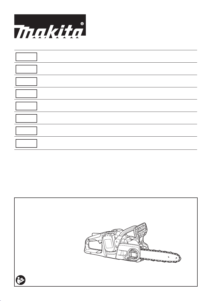
•
Maintainarmgrip,withthumbsandngersencir-
cling the chain saw handles, with both hands on
the saw and position your body and arm to allow
you to resist kickback forces. Kickback forces can
be controlled by the operator, if proper precautions
are taken. Do not let go of the chain saw.
►Fig.1
• Donotoverreachanddonotcutabove
shoulder height. This helps prevent unin-
tended tip contact and enables better control
of the chain saw in unexpected situations.
• Onlyusereplacementbarsandchainsspec-
iedbythemanufacturer.Incorrectreplace-
ment bars and chains may cause chain
breakage and/or kickback.
• Followthemanufacturer’ssharpeningand
maintenance instructions for the saw chain.
Decreasing the depth gauge height can lead
to increased kickback.
14. Before starting work, check that the chain
saw is in proper working order and that its
condition complies with the safety regulations.
Check in particular that:
• Thechainbrakeisworkingproperly;
• Therun-downbrakeisworkingproperly;
• Thebarandthesprocketcoveraretted
correctly;
• Thechainhasbeensharpenedandten-
sioned in accordance with the regulations.
15.
Do not start the chain saw with the chain cover
being installed on it. Starting the chain saw with the
chain cover being installed on it may cause the chain
covertothrownoutforwardresultinginpersonalinjury
anddamagetoobjectsaroundtheoperator.
SAVE THESE INSTRUCTIONS.
WARNING: DO NOT let comfort or familiarity
with product (gained from repeated use) replace
strict adherence to safety rules for the subject
product. MISUSE or failure to follow the safety
rules stated in this instruction manual may cause
serious personal injury.
Important safety instructions for
battery cartridge
1.
Before using battery cartridge, read all instruc-
tions and cautionary markings on (1) battery
charger, (2) battery, and (3) product using battery.
2. Do not disassemble battery cartridge.
3. If operating time has become excessively
shorter, stop operating immediately. It may
result in a risk of overheating, possible burns
and even an explosion.
4.
If electrolyte gets into your eyes, rinse them out
with clear water and seek medical attention right
away. It may result in loss of your eyesight.
5. Do not short the battery cartridge:
(1) Do not touch the terminals with any con-
ductive material.
(2) Avoid storing battery cartridge in a con-
tainer with other metal objects such as
nails, coins, etc.
(3) Do not expose battery cartridge to water
or rain.
A battery short can cause a large current
ow, overheating, possible burns and even a
breakdown.
6. Do not store the tool and battery cartridge in
locations where the temperature may reach or
exceed 50 °C (122 °F).
7. Do not incinerate the battery cartridge even if
it is severely damaged or is completely worn
out. The battery cartridge can explode in a re.
8. Be careful not to drop or strike battery.
9. Do not use a damaged battery.
10. The contained lithium-ion batteries are subject
to the Dangerous Goods Legislation require-
ments.
For commercial transports e.g. by third parties,
forwarding agents, special requirement on pack-
aging and labeling must be observed.
For preparation of the item being shipped, consult-
ing an expert for hazardous material is required.
Please also observe possibly more detailed
national regulations.
Tape or mask off open contacts and pack up the
battery in such a manner that it cannot move
around in the packaging.
11. Follow your local regulations relating to dis-
posal of battery.
SAVE THESE INSTRUCTIONS.
CAUTION: Only use genuine Makita batteries.
Use of non-genuine Makita batteries, or batteries that
have been altered, may result in the battery bursting
causingres,personalinjuryanddamage.Itwill
also void the Makita warranty for the Makita tool and
charger.

11 ENGLISH
Tips for maintaining maximum
battery life
1. Charge the battery cartridge before completely
discharged. Always stop tool operation and
charge the battery cartridge when you notice
less tool power.
2. Never recharge a fully charged battery car-
tridge. Overcharging shortens the battery
service life.
3. Charge the battery cartridge with room tem-
perature at 10 °C - 40 °C (50 °F - 104 °F). Let
a hot battery cartridge cool down before
charging it.
4. Charge the battery cartridge if you do not use
it for a long period (more than six months).
PARTS DESCRIPTION
►Fig.2
1Battery cartridge 2Front hand guard 3Guide bar
4Saw chain 5Lever 6Adjustingdial
7Check button 8Capacity indicator 9Main power lamp
10 Main power switch 11 Lock-off lever 12 Rear handle
13 Switch trigger 14 Front handle 15 Oil tank cap
16 Chain catcher 17 Adjustingscrew(foroilpump) 18 Guide bar cover
FUNCTIONAL
DESCRIPTION
CAUTION: Always be sure that the tool is
switched off and the battery cartridge is removed
before adjusting or checking function on the tool.
Installing or removing battery
cartridge
CAUTION: Always switch off the tool before
installing or removing of the battery cartridge.
CAUTION: Hold the tool and the battery car-
tridge rmly when installing or removing battery
cartridge. Failure to hold the tool and the battery
cartridgermlymaycausethemtoslipoffyourhands
and result in damage to the tool and battery cartridge
andapersonalinjury.
►Fig.3: 1. Red indicator 2. Button 3. Battery cartridge
To remove the battery cartridge, slide it from the tool
while sliding the button on the front of the cartridge.
To install the battery cartridge, align the tongue on the
battery cartridge with the groove in the housing and slip
it into place. Insert it all the way until it locks in place
with a little click. If you can see the red indicator on the
upper side of the button, it is not locked completely.
CAUTION: Always install the battery cartridge
fully until the red indicator cannot be seen. If not,
itmayaccidentallyfalloutofthetool,causinginjuryto
you or someone around you.
CAUTION: Do not install the battery cartridge
forcibly. If the cartridge does not slide in easily, it is
not being inserted correctly.
NOTE: The tool does not work with only one battery
cartridge.
NOTE:Payattentiontothepositionofyourn-
gers when installing the battery. The button will be
depressed unintentionally.
Tool / battery protection system
The tool is equipped with a tool/battery protection sys-
tem. This system automatically cuts off power to the
motor to extend tool and battery life. The tool will auto-
matically stop during operation if the tool or battery is
placed under one of the following conditions.
Overload protection
Whenthetoolisoperatedinamannerthatcausesit
to draw an abnormally high current, the tool automat-
ically stops and the main power lamp will blink. In this
situation, turn the tool off and stop the application that
caused the tool to become overloaded. Then turn the
tool on to restart.
Overheat protection
Whenthetoolisoverheated,thetoolautomatically
stops and the capacity indicator lamp will blink as illus-
trated. In this situation, let the tool cool down before
turning the tool on again.
Capacity indicator status Status
On Off Blinking
Overheated.
Overdischarge protection
Whenthebatterycapacitybecomeslow,thetoolstops
automatically. If the product does not operate even
when the switches are operated, remove the batteries
from the tool and charge the batteries.

12 ENGLISH
Indicating the remaining battery
capacity
►Fig.4: 1. Check button 2. Capacity indicator
The remaining battery capacity is shown while you
are pressing the check button. The capacity indicators
correspond to each battery.
Capacity indicator status Remaining
battery
capacity
On Off Blinking
50% to 100%
20% to 50%
0% to 20%
Charge the
battery
Indicating the remaining battery
capacity
Only for battery cartridges with the indicator
►Fig.5: 1. Indicator lamps 2. Check button
Press the check button on the battery cartridge to indi-
cate the remaining battery capacity. The indicator lamps
light up for few seconds.
Indicator lamps Remaining
capacity
Lighted Off Blinking
75% to 100%
50% to 75%
25% to 50%
0% to 25%
Charge the
battery.
The battery
may have
malfunctioned.
NOTE: Depending on the conditions of use and the
ambient temperature, the indication may differ slightly
from the actual capacity.
Main power switch
WARNING: Always turn off the main power
switch when not in use.
To stand by the chain saw, press the main power switch
until the main power lamp lights up. To turn off, press
the main power switch again.
►Fig.6: 1. Main power switch
NOTE: The main power lamp brinks if the switch
trigger is pulled under unoperatable conditions. The
lamp blinks if you
• turnonthemainpowerswitchwhileholding
downthelock-offleverandtheswitchtrigger;
• pulltheswitchtriggerwhilethechainbrakeis
applied;
• releasethechainbrakewhileholdingdownthe
lock-off lever and pulling the switch trigger.
NOTE: This chain saw employs the auto power-off
function. To avoid unintentional start up, the main
power switch will automatically shut down when the
switch trigger is not pulled for a certain period after
the main power switch is turned on.
Switch action
WARNING: For your safety, this tool is
equipped with lock-off lever which prevents the
tool from unintended starting. NEVER use the tool
if it runs when you simply pull the switch trigger
without pressing the lock-off lever. Return the
tool to our authorized service center for proper
repairs BEFORE further usage.
WARNING: NEVER tape down or defeat pur-
pose and function of lock-off lever.
CAUTION: Before installing the battery car-
tridge into the tool, always check to see that the
switch trigger actuates properly and returns to
the "OFF" position when released.
NOTICE: Do not pull the switch trigger hard with-
out pressing the lock-off lever. This can cause
switch breakage.
To prevent the switch trigger from being accidentally
pulled, a lock-off lever is provided. To start the tool,
depress the lock-off lever and pull the switch trigger.
Release the switch trigger to stop.
►Fig.7: 1. Switch trigger 2. Lock-off lever

13 ENGLISH
Checking the chain brake
CAUTION: Hold the chain saw with both
hands when switching it on. Hold the rear handle
with your right hand, the front handle with your
left. The bar and the chain must not be in contact
with any object.
CAUTION: Should the saw chain not stop
immediately when this test is performed, the
saw may not be used under any circumstances.
Consult our authorized service center.
1. Press the lock-off lever, then pull the switch trig-
ger. The saw chain starts immediately.
2. Push the front hand guard forwards with the back
of your hand. Make sure that the chain saw comes to an
immediate standstill.
►Fig.8: 1. Front hand guard 2. Unlocked position
3. Locked position
Checking the run-down brake
CAUTION: If the saw chain does not stop
within one second in this test, stop using the
chain saw and consult our authorized service
center.
Run the chain saw then release the switch trigger com-
pletely. The saw chain must come to a standstill within
one second.
Adjusting the chain lubrication
Youcanadjusttheoilpumpfeedratewiththeadjusting
screw.Theamountofoilcanbeadjustedusingthe
universal wrench.
►Fig.9: 1.Adjustingscrew
ASSEMBLY
CAUTION: Always be sure that the tool is
switched off and the battery cartridge is removed
before carrying out any work on the tool.
CAUTION: Do not touch the saw chain with
bare hands. Always wear gloves when handling
the saw chain.
Removing or installing saw chain
CAUTION: The saw chain and the guide bar
are still hot just after the operation. Let them cool
down enough before carrying out any work on
the tool.
Toremovethesawchain,performthefollowingsteps:
1. Pull the lever up while pressing its edge.
►Fig.10: 1. Lever
2. Turntheadjustingdialto"-"directiontorelease
the saw chain tension.
►Fig.11: 1.Adjustingdial
3. Turn the lever counterclockwise until the sprocket
cover comes off.
►Fig.12: 1. Lever 2. Sprocket cover
4. Remove the sprocket cover then remove the saw
chain and guide bar from the chain saw body.
Toinstallthesawchain,performthefollowingsteps:
1. Make sure the direction of the chain. The arrow
mark on the chain shows the direction of the chain.
2. Fit in one end of the saw chain on the top of the
guide bar and the other end around the sprocket.
►Fig.13: 1. Sprocket
3. Rest the guide bar in place on the chain saw.
4. Turntheadjustingdialto"-"directiontoslidethe
adjustingpininthedirectionofarrow.
►Fig.14: 1.Adjustingpin
5. Place the sprocket cover on the chain saw so that
theadjustingpinispositionedinasmallholeonthe
guide bar.
►Fig.15: 1. Sprocket cover 2. Guide bar 3. Hole
6. Turn the lever clockwise fully and a quarter turn
backtokeeploosenessforadjustingthechaintension.
7. Turntheadjustingdialtoadjustthechaintension.
8. Turn the lever clockwise until the sprocket cover is
secured then return it to the original position.
►Fig.16: 1. Lever 2. Sprocket cover
Adjusting saw chain tension
CAUTION: Carry out the procedure of install-
ing or removing saw chain in a clean place free
from sawdust and the like.
CAUTION: Do not tighten the saw chain too
much.Excessivelyhightensionofsawchainmay
cause breakage of saw chain, wear of the guide bar
andbreakageoftheadjustingdial.
CAUTION: A chain which is too loose can
jump off the bar and it may cause an injury
accident.
The saw chain may become loose after many hours
of use. From time to time check the saw chain tension
before use.
1. Press and fully open the lever until it clicks. Turn it
counterclockwise a little to loosen sprocket cover lightly.
►Fig.17: 1. Lever 2. Sprocket cover
2. Liftuptheguidebartipslightlyandadjustthe
chaintension.Turntheadjustingdialtothe"-"direction
to loosen, turn to the "+" direction to tighten. Tighten the
sawchainuntilthelowersideofthesawchaintsinthe
guide bar rail as illustrated.
►Fig.18: 1.Adjustingdial2. Guide bar 3. Saw chain
3. Keep holding the guide bar lightly and tighten the
sprocket cover. Make sure that the saw chain does not
loose at the lower side.
4. Return the lever to the original position.
►Fig.19: 1. Lever 2. Sprocket cover
Makesurethesawchaintssnuglyagainstthelower
side of the bar.

14 ENGLISH
OPERATION
Lubrication
Saw chain is automatically lubricated when the tool is in
operation. Check the amount of remaining oil in the oil
tank periodically.
Torellthetank,laythechainsawonitssideand
remove the oil tank cap. The proper amount of oil is 200
ml.Afterrellingthetank,makesurethattheoiltank
cap is tightened securely.
►Fig.20: 1. Oil tank cap 2. Oil tank (translucent)
Afterrelling,holdthechainsawawayfromthe
tree. Start it and wait until lubrication on saw chain is
adequate.
►Fig.21
NOTICE: When lling the chain oil for the rst
time, or relling the tank after it has been com-
pletely emptied, add oil up to the bottom edge of
the ller neck. The oil delivery may otherwise be
impaired.
NOTICE: Use the saw chain oil exclusively for
Makita chain saws or equivalent oil available in
the market.
NOTICE: Never use oil including dust and parti-
cles or volatile oil.
NOTICE: When pruning trees, use botanical oil.
Mineral oil may harm trees.
NOTICE: Before the cutting operation, make sure
that the provided oil tank cap is screwed in place.
WORKING WITH THE CHAIN SAW
CAUTION: The rst time user should, as a
minimum practice, do cutting logs on a saw-horse
or cradle.
CAUTION: When sawing precut timber, use a
safe support (saw horse or cradle). Do not steady
the workpiece with your foot, and do not allow
anyone else to hold or steady it.
CAUTION: Secure round pieces against
rotation.
CAUTION: Keep all parts of the body away
from the saw chain when the motor is operating.
CAUTION: Hold the chain saw rmly with
both hands when the motor is running.
CAUTION: Do not overreach. Keep proper
footing and balance at all times.
NOTICE: Never toss or drop the tool.
NOTICE: Do not cover the vents of the tool.
Bring the bottom edge of the chain saw body into
contact with the branch to be cut before switching on.
Otherwise it may cause the guide bar to wobble, result-
ingininjurytooperator.Sawthewoodtobecutbyjust
moving it down by using the weight of the chain saw.
►Fig.22
Ifyoucannotcutthetimberrightthroughwithasinglestroke:
Apply light pressure to the handle and continue sawing
anddrawthechainsawbackalittle;thenapplythe
spikebumperalittlelowerandnishthecutbyraising
the handle.
►Fig.23
Bucking
1. Rest the bottom edge of the chain saw body on
the wood to be cut.
►Fig.24
2. Withthesawchainrunning,sawintothewood
while using the rear handle to raise the saw and the
front one to guide it. Use the spike bumper as a pivot.
3. Continue the cut by applying slight pressure to
the front handle, easing the saw back slightly. Move
the spike bumper further down the timber and raise the
front handle again.
NOTICE: When making several cuts, switch the
chain saw off between cuts.
CAUTION: If the upper edge of the bar is used
for cutting, the chain saw may be deected in
your direction if the chain becomes trapped. For
this reason, cut with the lower edge, so that the
saw will be deected away from your body.
►Fig.25
Whenyoucutawoodundertension,cutthepressured
side(A)rst.Thenmakethenalcutfromthetensioned
side (B). This prevents the bar from becoming trapped.
►Fig.26
Limbing
CAUTION: Limbing may only be performed by
trained persons. A hazard is presented by the risk
of kickback.
Whenlimbing,supportthechainsawonthetrunkif
possible. Do not cut with the tip of the bar, as this pres-
ents a risk of kickback.
Pay particular attention to branches under tension. Do
not cut unsupported branches from below.
Do not stand on the felled trunk when limbing.
Burrowing and parallel-to-grain cuts
CAUTION: Burrowing and parallel-to-grain
cuts may only be carried out by persons with
special training. The possibility of kickback presents
ariskofinjury.
Perform parallel-to-grain cuts at as shallow an angle as
possible. Take an extra caution when carrying out the
cut as the spike bumper cannot be used.
►Fig.27
Felling
CAUTION: Felling work may only be per-
formed by trained persons. The work is hazardous.
Observe local regulations if you wish to fell a tree.

15 ENGLISH
►Fig.28: 1. Felling area
— Beforestartingfellingwork,ensurethat:
• Onlypersonsinvolvedinthefellingoperation
areinthevicinity;
• Anypersoninvolvedhasanunhinderedpath
of retreat through a range of approximately
45° either side of the felling axis. Consider
the additional risk of tripping over electrical
cables;
• Thebaseofthetrunkisfreeofforeign
objects,rootsandranches;
• Nopersonsorobjectsarepresentovera
distance of 2 1/2 tree lengths in the direction
in which the tree will fall.
— Considerthefollowingwithrespecttoeachtree:
• Directionoflean;
• Looseordrybranches;
• Heightofthetree;
• Naturaloverhang;
• Whetherornotthetreeisrotten.
— Consider the wind speed and direction. Do not
carry out felling work if the wind is gusting strongly.
— Trimmingofrootswellings:Beginwiththelargest
swellings.Maketheverticalcutrst,thenthe
horizontal cut.
— Stand to the side of the falling tree. Keep an area
clear to the rear of the falling tree up to an angle of
45° either side of the tree axis (refer to the “felling
area”gure).Payattentiontofallingbranches.
— An escape path should be planned and cleared
as necessary before cuts are started. The escape
path should extend back and diagonally to the rear
oftheexpectedlineoffallasillustratedingure.
►Fig.29: 1. Felling direction 2. Danger zone
3.Escaperoute
Whenfellingtrees,followtheproceduersbelow:
1. Cut a scarf as close to the ground as possible.
First make the horizontal cut to a depth of 1/5 -1/3 of the
trunk diameter. Do not make the scarf too large. Then
make the diagonal cut.
►Fig.30
NOTE: The scarf determines the direction in which
the tree will fall, and guides it. It is made on the side
towards which the tree is to fall.
2. Make the back cut a little higher than the base
cut of the scarf. The back cut must be exactly horizon-
tal. Leave approximately 1/10 of the trunk diameter
betweenthebackcutandthescarf.Thewoodbersin
the uncut trunk portion act as a hinge. Insert wedges
into the back cut in time.
►Fig.31
WARNING: Do not cut right through the bers
under any circumstances. The tree will otherwise
fall unchecked.
NOTICE: Only plastic or aluminum wedges may
be used to keep the back cut open. The use of
iron wedges is prohibited.
Carrying tool
Before carrying the tool, always apply the chain brake
and remove the battery cartridges from the tool. Then
attach the guide bar cover. Also cover the battery car-
tridge with the battery cover.
►Fig.32: 1. Guide bar cover 2. Battery cover
MAINTENANCE
CAUTION: Always be sure that the tool is
switched off and the battery cartridge is removed
before attempting to perform inspection or
maintenance.
CAUTION: Always wear gloves when perform-
ing any inspection or maintenance.
NOTICE: Never use gasoline, benzine, thinner,
alcohol or the like. Discoloration, deformation or
cracks may result.
Sharpening the saw chain
Sharpen the saw chain when:
• Mealysawdustisproducedwhendampwoodis
cut;
• Thechainpenetratesthewoodwithdifculty,even
whenheavypressureisapplied;
• Thecuttingedgeisobviouslydamaged;
• Thesawpullstotheleftorrightinthewood.
(caused by uneven sharpening of the saw chain or
damage to one side only)
Sharpen the saw chain frequently but a little each time.
Twoorthreestrokeswithaleareusuallysufcientfor
routineresharpening.Whenthesawchainhasbeen
resharpened several times, have it sharpened in our
authorized service center.
Sharpening criteria:
WARNING: An excessive distance between
the cutting edge and depth gauge increases the
risk of kickback.
►Fig.33: 1. Cutter length 2. Distance between cutting
edge and depth gauge 3. Minimum cutter
length (3 mm)
— All cutter length must be equal. Different cutter
lengths prevent the saw chain from running
smoothly and may cause the saw chain to break.
— Do not sharpen the chain when the cutter length
has reached 3 mm or shorter. The chain must be
replaced with new one.
— The chip thickness is determined by the distance
between the depth gauge (round nose) and the
cutting edge.
— The best cutting results are obtained with following
distance between cutting edge and depth gauge.
• Chainblade90PX:0.65mm(0.025″)
• Chainblade91PX:0.65mm(0.025″)
►Fig.34

16 ENGLISH
— The sharpening angle of 30° must be the same on
all cutters. Different cutter angles cause the chain
to run roughly and unevenly, accelerate wear, and
lead to chain breaks.
— Useasuitableroundlesothatthepropersharp-
ening angle is kept against the teeth.
• Chainblade90PX:55°
• Chainblade91PX:55°
File and le guiding
— Useaspecialroundle(optionalaccessory)for
saw chains to sharpen the chain. Normal round
lesarenotsuitable.
— Diameteroftheroundleforeachsawchainisas
follows:
• Chainblade90PX:4.5mm(3/16″)
• Chainblade91PX:4.0mm(5/32″)
— Theleshouldonlyengagethecutteronthefor-
wardstroke.Lifttheleoffthecutteronthereturn
stroke.
— Sharpentheshortestcutterrst.Thenthelength
of this shortest cutter becomes the standard for all
other cutters on the saw chain.
— Guidetheleasshowninthegure.
►Fig.35: 1. File 2. Saw chain
— Thelecanbeguidedmoreeasilyifaleholder
(optionalaccessory)isemployed.Theleholder
has markings for the correct sharpening angle of
30° (align the markings parallel to the saw chain)
and limits the depth of penetration (to 4/5 of the
lediameter).
►Fig.36: 1. File holder
— After sharpening the chain, check the height of the
depth gauge using the chain gauge tool (optional
accessory).
►Fig.37
— Removeanyprojectingmaterial,howeversmall,
withaspecialatle(optionalaccessory).
— Round off the front of the depth gauge again.
Cleaning the guide bar
Chips and sawdust will build up in the guide bar groove.
Theymayclogthebargrooveandimpairtheoilow.
Clean out the chips and sawdust every time when you
sharpen or replace the saw chain.
►Fig.38
Cleaning the sprocket cover
Chips and saw dust will accumulate inside of the
sprocket cover. Remove the sprocket cover and saw
chain from the tool then clean the chips and saw dust.
►Fig.39
Cleaning the oil discharge hole
Small dust or particles may be built up in the oil dis-
charge hole during operation. These dust or particles
mayimpairtheoiltoowandcauseaninsufcient
lubricationonthewholesawchain.Whenapoorchain
oil delivery occurs at the top of guide bar, clean the oil
discharge hole as follows.
1. Remove the sprocket cover and saw chain from
the tool.
2. Remove the small dust or particles using a slotted
screwdriver with a slender shaft or the like.
►Fig.40: 1. Slotted screwdriver 2. Oil discharge hole
3. Insert the battery cartridge into the tool. Pull the
switchtriggertoowbuilt-updustorparticlesofftheoil
discharge hole by discharging chain oil.
4. Remove the battery cartridge from the tool.
Reinstall the sprocket cover and saw chain on the tool.
Replacing the sprocket
CAUTION: A worn sprocket will damage a
new saw chain. Have the sprocket replaced in this
case.
Beforettinganewsawchain,checktheconditionof
the sprocket.
►Fig.41: 1. Sprocket 2. Areas to be worn out
Alwaystanewlockingringwhenreplacingthe
sprocket.
►Fig.42: 1. Locking ring 2. Sprocket
NOTICE: Make sure that the sprocket is installed
as shown in the gure.
Storing the tool
1. Clean the tool before storing. Remove any chips
and sawdust from the tool after removing the sprocket
cover.
2. After cleaning the tool, run it under no load to lubri-
cate the saw chain and guide bar.
3. Cover the guide bar with the guide bar cover.
4. Emptytheoiltank.

17 ENGLISH
Instructions for periodic maintenance
To ensure long life, prevent damage and ensure the full functioning of the safety features, the following maintenance
mustbeperformedregularly.Warrantyclaimscanberecognizedonlyifthisworkisperformedregularlyandprop-
erly. Failure to perform the prescribed maintenance work can lead to accidents! The user of the chain saw must not
perform maintenance work which is not described in the instruction manual. All such work must be carried out by our
authorized service center.
Check item / Operating time Before
operation
Everyday Every week Every 3
month
Annually Before
storage
Chain saw Inspection. -----
Cleaning. -----
Check at
authorized
service center.
----
Saw chain Inspection. -----
Sharpening if
necessary.
-----
Guide bar Inspection. ----
Remove from
the chain saw.
-----
Chain brake Check the
function.
-----
Have it
inspected
regularly at
authorized
service center.
--- - -
Chain
lubrication
Check the oil
feed rate.
-----
Switch trigger Inspection. -----
Lock-off lever Inspection. -----
Oil tank cap Check
tightness.
-----
Chain catcher Inspection. - - ---
Screws and
nuts
Inspection. - - ---
TomaintainproductSAFETYandRELIABILITY,
repairs,anyothermaintenanceoradjustmentshould
be performed by Makita Authorized or Factory Service
Centers, always using Makita replacement parts.

18 ENGLISH
TROUBLESHOOTING
Beforeaskingforrepairs,conductyourowninspectionrst.Ifyoundaproblemthatisnotexplainedinthemanual,
do not attempt to dismantle the tool. Instead, ask Makita Authorized Service Centers, always using Makita replace-
ment parts for repairs.
Malfunction status Cause Action
The chain saw does not start. Two battery cartridges are not installed. Install two charged battery cartridges.
Battery problem (low voltage). Recharge the battery cartridges. If recharg-
ing is not effective, replace the battery
cartridge.
Main power switch is off. The chain saw is automatically turned off if
it is un-operated for a certain period. Turn
on the main power switch again.
The saw chain does not run. Chain brake activated. Release chain brake.
The motor stops running after a little use. Battery's charge level is low. Recharge the battery cartridges. If recharg-
ing is not effective, replace the battery
cartridge.
No oil on the chain. Oil tank is empty. Fill the oil tank.
Oil guide groove is dirty. Clean the groove.
Poor oil delivery. Adjusttheamountofoildeliverywiththe
adjustingscrew.
The chain saw does not reach maximum
RPM.
Battery cartridge is installed improperly. Install the battery cartridges as described
in this manual.
Battery power is dropping. Recharge the battery cartridges. If recharg-
ing is not effective, replace the battery
cartridge.
The drive system does not work correctly. Ask the authorized service center in your
region for repair.
The main power lamp is blinking. Switch trigger is pulled under an unoperat-
able condition.
Pull the switch trigger after the main power
switch is turned on and the chain brake is
released.
Chain does not stop even the chain brake
isactivated:
Stop the machine immediately!
The brake band is worn down. Ask the authorized service center in your
region for repair.
Abnormalvibration:
Stop the machine immediately!
Loose guide bar or saw chain. Adjusttheguidebarandsawchain
tension.
Tool malfunction. Ask the authorized service center in your
region for repair.
OPTIONAL
ACCESSORIES
CAUTION: These accessories or attachments
are recommended for use with your Makita tool
specied in this manual. The use of any other
accessories or attachments might present a risk of
injurytopersons.Onlyuseaccessoryorattachment
for its stated purpose.
If you need any assistance for more details regard-
ing these accessories, ask your local Makita Service
Center.
• Sawchain
• Guidebar
• Guidebarcover
• File
• Toolbag
• Makitagenuinebatteryandcharger
WARNING: If you purchase a guide bar of
different length from the standard guide bar, also
purchase a suitable guide bar cover together. It
must t and fully cover the guide bar on the chain
saw.
NOTE: Some items in the list may be included in the
tool package as standard accessories. They may
differ from country to country.

19 SVENSKA
SVENSKA (Originalinstruktioner)
SPECIFIKATIONER
Modell: DUC303 DUC353 DUC400
Total längd (utan svärd) 443 mm
Märkspänning 36 V likström
Standardbatterikassett BL1815N, BL1820, BL1820B, BL1830, BL1830B, BL1840,
BL1840B, BL1850, BL1850B, BL1860B
Nettovikt
(vid användning av BL1815N)
med 90PX 4,6 kg 4,7 kg 4,8 kg
med 91PX 4,7 kg 4,8 kg 4,9 kg
Standard svärdlängd 300 mm 350 mm 400 mm
Rekommenderad svärdlängd 300 - 400 mm
Appliceradsågkedjetyp
(se tabellen nedan)
90PX
91PX
Kedjehjul Antal tänder 6
Vinkel 3/8″
Kedjehastighet 0 - 20 m/s
(0 - 1 200 m/min)
Tankvolymkedjeolja 200 cm3
Sågkedja och svärd
Såpgkedjetyp 90PX
Antal drivlänkar 46 52 56
Svärd Svärdlängd 300 mm 350 mm 400 mm
Såglängd 280 mm 330 mm 375 mm
Vinkel 3/8″
Mätare 1,1 mm
Typ Kuggdrev
Såpgkedjetyp 91PX
Antal drivlänkar 46 52 56
Svärd Svärdlängd 300 mm 350 mm 400 mm
Såglängd 280 mm 330 mm 375 mm
Vinkel 3/8″
Mätare 1,3 mm
Typ Kuggdrev
• Pågrundavvårtpågåendeprogramförforskningochutvecklingkandessaspecikationerändrasutanföregå-
ende meddelande.
• Specikationerochbatterikassettkanvarieramellanolikaländer.
• Vikt,medbatterikassett,ienlighetmedEPTA-procedure01/2003
VARNING:Användenlämpligkombinationavsvärdochsågkedje.Iannatfallkanpersonskadauppstå.
Symboler
Följandevisarsymbolernasomanvändsförutrust-
ningen. Se till att du förstår innebörden innan du använ-
der borrmaskinen.
Läs igenom bruksanvisningen.
Använd skyddsglasögon.
Använd hörselskydd.
Användhjälm,skyddsglasögonoch
hörselskydd.
Använd lämpliga skydd för fötterna/benen
och händerna/armarna.
Utsätt inte verktyget för fukt.

20 SVENSKA
Maximal tillåten kaplängd
Kedjansrotationsriktning
Justeringavkedjeolja
Cd
Ni-MH
Li-ion
GällerendastinomEU
Elektriskutrustningellerbatteripaketfår
inte kastas i hushållsavfallet!
EnligtEU-direktivensomavserförbrukad
elektrisk och elektronisk utrustning, batterier,
ackumulatorer, förbrukade batterier och acku-
mulatorer, samt direktivens tillämpning enligt
nationelllagstiftning,skauttjäntelektrisk
utrustning, batterier och batteripaket sorteras
separatochlämnastillmiljövänligåtervinning.
Avsedd användning
Dennakedjesågärendastavseddförsågningiträ.
Buller
Den normala bullernivån för A-belastning är bestämd
enligtEN60745:
Model DUC303
Ljudtrycksnivå(LpA):87,7dB(A)
Ljudeffektnivå(LWA):100,4dB(A)
Mättolerans(K):2dB(A)
Model DUC353
Ljudtrycksnivå(LpA):87,7dB(A)
Ljudeffektnivå(LWA):100,4dB(A)
Mättolerans(K):2dB(A)
VARNING: Använd hörselskydd.
Vibration
Det totala vibrationsvärdet (treaxlad vektorsumma)
bestämtenligtEN60745:
Model DUC303
Arbetsläge:sågningiträ
Vibrationsemission (ah,W):5,3m/s2
Mättolerans(K):1,5m/s2
Model DUC353
Arbetsläge:sågningiträ
Vibrationsemission (ah,W):5,3m/s2
Mättolerans(K):1,5m/s2
OBS:
Det deklarerade vibrationsemissionsvärdet har
uppmätts i enlighet med standardtestmetoden och kan
användasförattjämföraenmaskinmedenannan.
OBS:
Det deklarerade vibrationsemissionsvärdet kan också
användas i en preliminär bedömning av exponering för vibration.
VARNING:
Viberationsemissionen under faktisk
användningavmaskinenkanskiljasigfråndetdeklarerade
emissionsvärdet, beroende på hur maskinen används.
VARNING:
Varnogamedattidentierasäkerhets-
åtgärder för att skydda användaren, vilka är grundade
på en uppskattning av graden av exponering för vibra-
tioner under de faktiska användningsförhållandena, (ta,
förutom avtryckartiden, med alla delar av användarcy-
keln i beräkningen, som till exempel tiden då maskinen
är avstängd och när den går på tomgång).
EG-försäkran om överensstämmelse
Gäller endast inom EU
EG-försäkranomöverensstämmelseinkluderassom
bilaga A till denna bruksanvisning.
SÄKERHETSVARNINGAR
Allmänna säkerhetsvarningar för
maskiner
VARNING: Läs alla säkerhetsvarningar, anvis-
ningar, illustrationer och specikationer som
medföljer det här maskinen.Underlåtenhetattfölja
instruktionerna kan leda till elstötar, brand och/eller
allvarliga personskador.
Spara alla varningar och instruk-
tioner för framtida referens.
Termen ”maskin” som anges i varningarna hänvisar till
din eldrivna maskin (sladdansluten) eller batteridrivna
maskin (sladdlös).
Säkerhetsvarningar för batteridriven
kedjesåg
1. Håll alla kroppsdelar borta från kedjesågen när
den är igång. Se till att sågkedjan inte vidrör
någonting innan du startar kedjesågen.Ett
ögonblick av ouppmärksamhet medan du arbetar
medkedjesågenkanledatillattkedjesågenkom-
mer i kontakt med dina kläder eller med kroppen.
2.
Håll alltid kedjesågen med din högerhand på det bakre
handtaget och din vänsterhand på det främre hand-
taget.Omduhållerikedjesågenmedhändernatvärtom
ökar risken för personskador, vilket absolut inte får ske.
3. Håll endast maskinen i de isolerade handtagen
om det nns risk för att sågkedjan kan komma
i kontakt med en dold elkabel.Omsågkedjan
kommer i kontakt med en strömförande ledning
blir maskinens metalldelar strömförande och kan
ge operatören en elektrisk stöt.
4.
Använd skyddsglasögon och hörselskydd.
Ytterligare skyddsutrustning för huvud, händer, ben
och fötter rekommenderas. Passande skyddskläder
minskarriskenförpersonskadorfrånygandemate-
rialresterelleroavsiktligkontaktmedsågkedjan.
5. Arbeta inte med kedjesågen i ett träd. Att
arbetamedkedjesågenuppeiettträdkanorsaka
personskador.
6. Stå alltid stadigt och arbeta endast med kedje-
sågen när du står på ett fast, säkert och plant
underlag. Halt eller ostadigt underlag såsom
stegar kan leda till att du tappar balansen eller
tapparkontrollenöverkedjesågen.
7. Var uppmärksam vid sågning av en gren som
är spänd eftersom den kan fjädra tillbaka. När
spänningeniträbrernasläpperkandenspända
grenen slå tillbaka mot användaren och/eller slå
kedjesågenurhänderna.
This manual suits for next models
3
Table of contents
Languages:
Other Makita Chainsaw manuals

Makita
Makita DCS4600S User manual

Makita
Makita DUC302Z User manual

Makita
Makita DUC252 User manual

Makita
Makita BUC121 User manual

Makita
Makita XCU11 User manual

Makita
Makita DUC356 User manual

Makita
Makita DCS510 Instruction Manual

Makita
Makita DUC303 User manual

Makita
Makita DUC407 User manual

Makita
Makita DCS230T User guide

Makita
Makita DUC356Z User manual

Makita
Makita EA3500SRDB Instruction Manual

Makita
Makita UC011G User manual

Makita
Makita DCS430 User manual

Makita
Makita DUC357 User manual

Makita
Makita DUC306 User manual

Makita
Makita UC 4001A User manual

Makita
Makita DCS6401-20 User manual

Makita
Makita EA3700T User guide

Makita
Makita BUC250 User manual