Makita DUC307 User manual

DUC307
DUC357
DUC407
EN Cordless Chain Saw INSTRUCTION MANUAL 9
SV Batteridriven kedjesåg BRUKSANVISNING 22
NO Batteridrevet kjedesag BRUKSANVISNING 34
FI Langaton ketjusaha KÄYTTÖOHJE 46
DA Akku-kædesav BRUGSANVISNING 58
LV Bezvada motorzāģis LIETOŠANAS INSTRUKCIJA 71
LT Belaidis grandininis pjūklas NAUDOJIMO INSTRUKCIJA 83
ET Juhtmeta kettsaag KASUTUSJUHEND 96
RU Цепная пила с питанием от
аккумуляторной батареи РУКОВОДСТВО ПО
ЭКСПЛУАТАЦИИ 109

2
Fig.1
1
34
5
6
7
8
9
10
11
13
14
2
12
Fig.2
1
2
3
Fig.3
1
2
Fig.4

3
1
2
Fig.5
2
1
3
23
1
Fig.6
1
Fig.7
1
2
Fig.8
1
Fig.9
1
Fig.10
1
2
Fig.11

4
3
1
2
Fig.12
1
2
Fig.13
1
Fig.14
1
Fig.15
2
1
Fig.16
1
Fig.17
2
1
Fig.18

5
2
3
1
Fig.19
1
2
Fig.20
1
2
Fig.21
Fig.22
Fig.23
Fig.24
Fig.25
Fig.26

6
A
B
A
B
Fig.27
Fig.28
2
1
/2
45o
1
45o
Fig.29
1
2
2
33
Fig.30
Fig.31
Fig.32
1
2
Fig.33
22
11
31
Fig.34

7
30
30
55 55
Fig.35
1
2
Fig.36
30
1/5
1
Fig.37
Fig.38
Fig.39
Fig.40
2
1
Fig.41
1
2
Fig.42

8
12
Fig.43

9ENGLISH
ENGLISH (Original instructions)
SPECIFICATIONS
Model: DUC307 DUC357 DUC407
Overall length
(without guide bar)
428 mm
Rated voltage D.C. 18 V
Net weight *1 2.9 kg
*2 4.2 - 4.3 kg
Standard guide bar length 300 mm 350 mm 400 mm
Recommended guide bar length 300 - 400 mm
Applicable saw chain type
(refer to the table below)
90PX
Sprocket Number of teeth 6
Pitch 3/8″
Chain speed 0 - 7.7 m/s
(0 - 460 m/min)
Chain oil tank volume 150 cm3
• Duetoourcontinuingprogramofresearchanddevelopment,thespecicationshereinaresubjecttochange
without notice.
• Specicationsmaydierfromcountrytocountry.
*1: Weight, without the saw chain, guide bar, guide bar cover, oil and battery cartridge(s).
*2:Thelightestandheaviestcombinationofweight,accordingtoEPTA-Procedure01/2014.Theweightmaydier
depending on the attachment(s), including the battery cartridge(s).
Saw chain, guide bar, and sprocket combination
Saw chain type 90PX
Number of drive links 46 52 56
Guide bar Guide bar length 300 mm 350 mm 400 mm
Cutting length 275 mm 330 mm 370 mm
Pitch 3/8″
Gauge 1.1 mm
Type Sprocket nose bar
Sprocket Number of teeth 6
Pitch 3/8″
WARNING:Useappropriatecombinationoftheguidebarandsawchain.Otherwisepersonalinjurymay
result.
Applicable battery cartridge and charger
Battery cartridge BL1830B / BL1840B / BL1850B / BL1860B
Charger DC18RC / DC18RD / DC18RE / DC18SD / DC18SE / DC18SF /
DC18SH
•
Some of the battery cartridges and chargers listed above may not be available depending on your region of residence.
WARNING: Only use the battery cartridges and chargers listed above. Use of any other battery cartridges
andchargersmaycauseinjuryand/orre.
Recommended cord connected power source
Portable power pack PDC01
• The cord connected power source(s) listed above may not be available depending on your region of residence.
• Before using the cord connected power source, read instruction and cautionary markings on them.

10 ENGLISH
Symbols
The followings show the symbols which may be used
for the equipment. Be sure that you understand their
meaning before use.
Read instruction manual.
Wear safety glasses.
Wear ear protection.
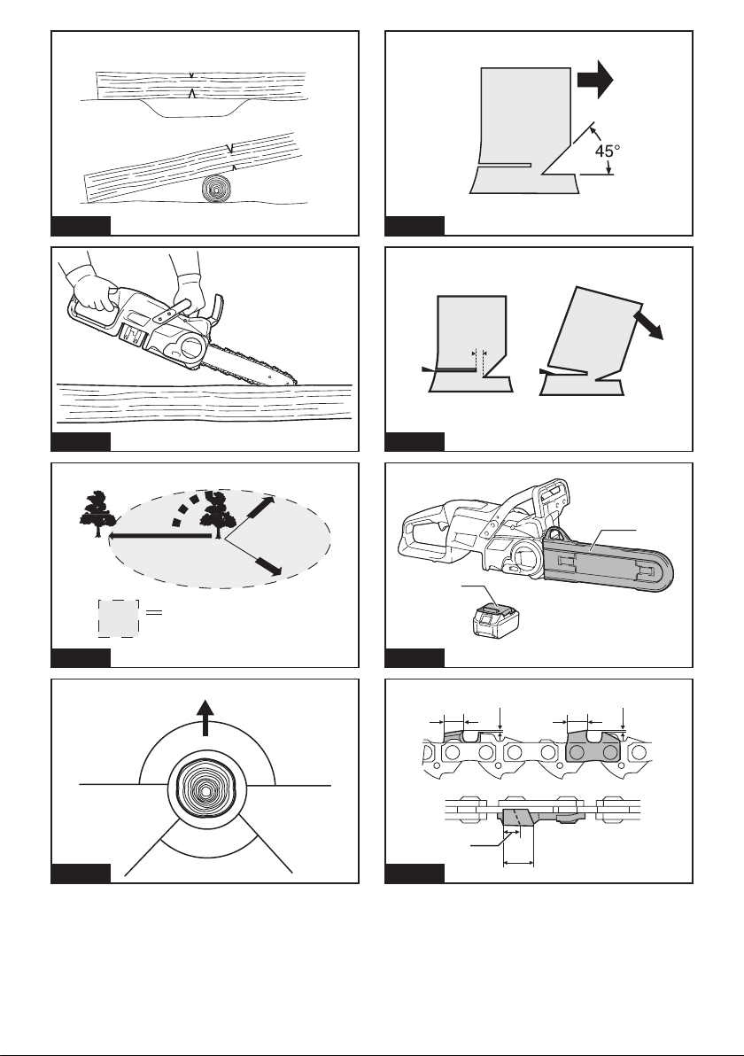
Maximum permissible cut length
Always use two hands when operating the
chain saw.
Beware of chain saw kickback and avoid
contact with bar tip.
Do not expose to moisture.
Direction of chain travel
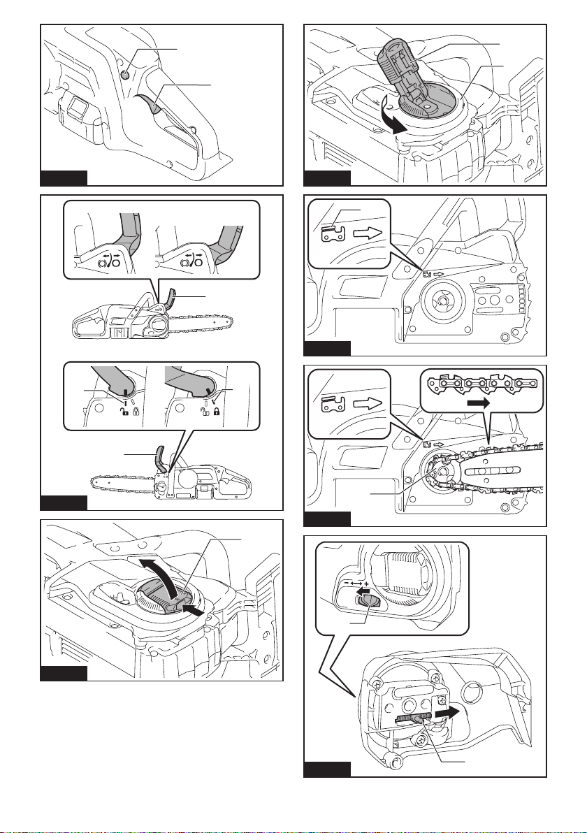
Sawchainoiladjustment
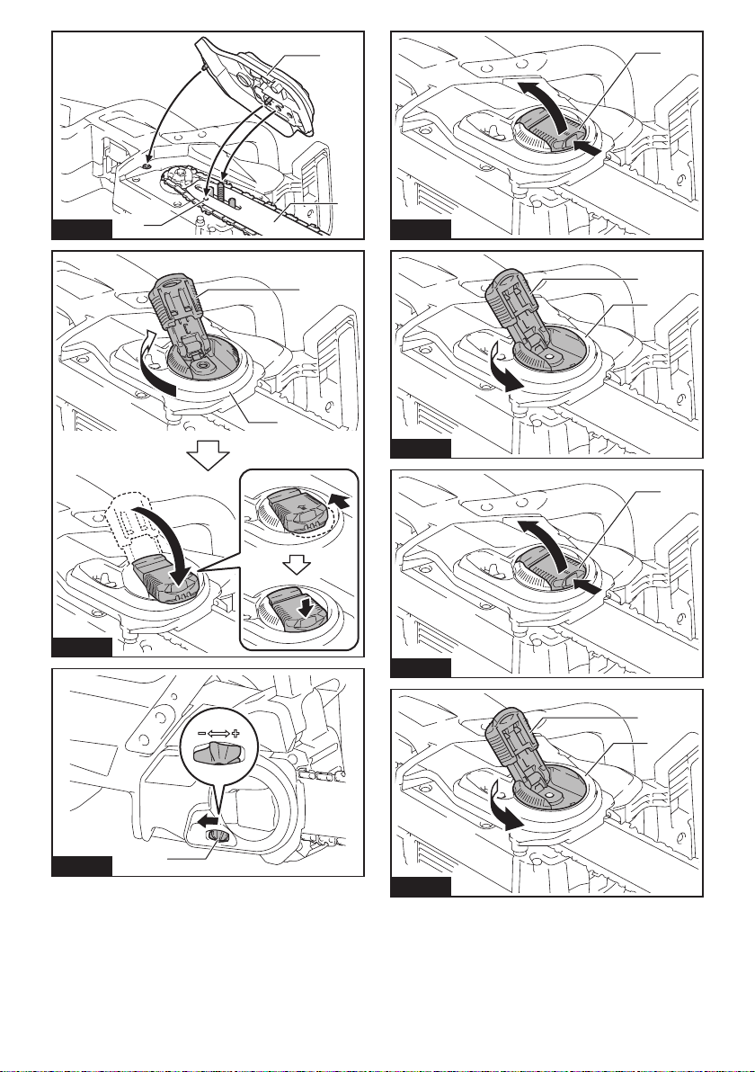
Ni-MH
Li-ion
Only for EU countries
Due to the presence of hazardous com-
ponents in the equipment, waste electrical
and electronic equipment, accumulators
and batteries may have a negative impact
on the environment and human health.
Do not dispose of electrical and electronic
appliances or batteries with household
waste!
In accordance with the European Directive
on waste electrical and electronic equip-
ment and on accumulators and batteries
and waste accumulators and batteries,
as well as their adaptation to national law,
waste electrical equipment, batteries and
accumulators should be stored separately
and delivered to a separate collection point
for municipal waste, operating in accor-
dance with the regulations on environmen-
tal protection.
This is indicated by the symbol of the
crossed-out wheeled bin placed on the
equipment.
Guaranteed sound power level according
to EU Outdoor Noise Directive.
Sound power level according to Australia
NSW Noise Control Regulation.
Intended use
This chain saw is intended for sawing wood.
Noise
The typical A-weighted noise level determined accord-
ing to EN62841-4-1:
Model DUC307
Sound pressure level (LpA) : 86 dB (A)
Sound power level (LWA) : 97 dB (A)
Uncertainty (K) : 3 dB (A)
Model DUC357
Sound pressure level (LpA) : 86 dB(A)
Sound power level (LWA) : 97 dB (A)
Uncertainty (K) : 3 dB(A)
Model DUC407
Sound pressure level (LpA) : 86 dB(A)
Sound power level (LWA) : 97 dB (A)
Uncertainty (K) : 3 dB(A)
NOTE: The declared noise emission value(s) has
been measured in accordance with a standard test
method and may be used for comparing one tool with
another.
NOTE: The declared noise emission value(s)
may also be used in a preliminary assessment of
exposure.
WARNING: Wear ear protection.
WARNING: The noise emission during actual
use of the power tool can dier from the declared
value(s) depending on the ways in which the
tool is used especially what kind of workpiece is
processed.
WARNING: Be sure to identify safety mea-
sures to protect the operator that are based on an
estimation of exposure in the actual conditions of
use (taking account of all parts of the operating
cycle such as the times when the tool is switched
o and when it is running idle in addition to the
trigger time).
Vibration
The vibration total value (tri-axial vector sum) deter-
mined according to EN62841-4-1:
Model DUC307
Work mode: cutting wood
Vibration emission (ah,W) : 5.4 m/s2
Uncertainty (K) : 1.5 m/s2
Model DUC357
Work mode: cutting wood
Vibration emission (ah,W) : 5.4 m/s2
Uncertainty (K) : 1.5 m/s2
Model DUC407
Work mode: cutting wood
Vibration emission (ah,W) : 5.4 m/s2
Uncertainty (K) : 1.5 m/s2
NOTE: The declared vibration total value(s) has been
measured in accordance with a standard test method
and may be used for comparing one tool with another.
NOTE: The declared vibration total value(s) may also
be used in a preliminary assessment of exposure.

11 ENGLISH
WARNING: The vibration emission during
actual use of the power tool can dier from the
declared value(s) depending on the ways in which
the tool is used especially what kind of workpiece
is processed.
WARNING: Be sure to identify safety mea-
sures to protect the operator that are based on an
estimation of exposure in the actual conditions of
use (taking account of all parts of the operating
cycle such as the times when the tool is switched
o and when it is running idle in addition to the
trigger time).
EC Declaration of Conformity
For European countries only
The EC declaration of conformity is included as Annex A
to this instruction manual.
SAFETY WARNINGS
General power tool safety warnings
WARNING: Read all safety warnings, instruc-
tions, illustrations and specications provided
with this power tool. Failure to follow all instructions
listedbelowmayresultinelectricshock,reand/or
seriousinjury.
Save all warnings and instruc-
tions for future reference.
The term "power tool" in the warnings refers to your
mains-operated (corded) power tool or battery-operated
(cordless) power tool.
General chain saw safety warnings
1. Keep all parts of the body away from the saw
chain when the chain saw is operating. Before
you start the chain saw, make sure the saw
chain is not contacting anything. A moment of
inattention while operating chain saws may cause
entanglement of your clothing or body with the
saw chain.
2. Always hold the chain saw with your right
hand on the rear handle and your left hand on
the front handle. Holding the chain saw with a
reversedhandcongurationincreasestheriskof
personalinjuryandshouldneverbedone.
3. Hold the chain saw by insulated gripping sur-
faces only, because the saw chain may contact
hidden wiring. Saw chains contacting a "live"
wire may make exposed metal parts of the chain
saw "live" and could give the operator an electric
shock.
4. Wear eye protection. Further protective equip-
ment for hearing, head, hands, legs and feet is
recommended. Adequate protective equipment
willreducepersonalinjuryfromyingdebrisor
accidental contact with the saw chain.
5. Do not operate a chain saw in a tree, on a lad-
der, from a rooftop, or any unstable support.
Operation of a chain saw in this manner could
resultinseriouspersonalinjury.
6. Always keep proper footing and operate the
chain saw only when standing on xed, secure
and level surface. Slippery or unstable surfaces
may cause a loss of balance or control of the
chain saw.
7. When cutting a limb that is under tension, be
alert for spring back. When the tension in the
woodbresisreleased,thespringloadedlimb
may strike the operator and/or throw the chain
saw out of control.
8.
Use extreme caution when cutting brush and sap-
lings. The slender material may catch the saw chain
andbewhippedtowardyouorpullyouobalance.
9. Carry the chain saw by the front handle with
the chain saw switched o and away from your
body. When transporting or storing the chain
saw, always t the guide bar cover. Proper
handling of the chain saw will reduce the likelihood
of accidental contact with the moving saw chain.
10. Follow instructions for lubricating, chain
tensioning and changing the bar and chain.
Improperly tensioned or lubricated chain may
either break or increase the chance for kickback.
11. Cut wood only. Do not use chain saw for pur-
poses not intended. For example: do not use
chain saw for cutting metal, plastic, masonry
or non-wood building materials. Use of the
chainsawforoperationsdierentthanintended
could result in a hazardous situation.
12. Do not attempt to fell a tree until you have an
understanding of the risks and how to avoid
them.Seriousinjurycouldoccurtotheoperatoror
bystanders while felling a tree.
13. Causes and operator prevention of kickback:
Kickback may occur when the nose or tip of the
guidebartouchesanobject,orwhenthewood
closes in and pinches the saw chain in the cut.
Tip contact in some cases may cause a sudden
reverse reaction, kicking the guide bar up and
back towards the operator.
Pinching the saw chain along the top of the guide
bar may push the guide bar rapidly back towards
the operator.
Either of these reactions may cause you to lose
control of the saw which could result in serious
personalinjury.Donotrelyexclusivelyuponthe
safety devices built into your saw. As a chain saw
user, you should take several steps to keep your
cuttingjobsfreefromaccidentorinjury.
Kickback is the result of chain saw misuse and/or
incorrect operating procedures or conditions and
can be avoided by taking proper precautions as
given below:
• Maintain a rm grip, with thumbs and
ngers encircling the chain saw handles,
with both hands on the saw and position
your body and arm to allow you to resist
kickback forces. Kickback forces can be
controlled by the operator, if proper precau-
tions are taken. Do not let go of the chain
saw.
►Fig.1

12 ENGLISH
• Do not overreach and do not cut above
shoulder height. This helps prevent unin-
tended tip contact and enables better control
of the chain saw in unexpected situations.
• Only use replacement guide bars and saw
chains specied by the manufacturer.
Incorrect replacement guide bars and saw
chains may cause chain breakage and/or
kickback.
• Follow the manufacturer’s sharpening
and maintenance instructions for the saw
chain. Decreasing the depth gauge height
can lead to increased kickback.
14. Follow all instructions when clearing jammed
material, storing or servicing the chain saw.
Make sure the switch is o and the battery
pack is removed. Unexpected actuation of the
chainsawwhileclearingjammedmaterialor
servicingmayresultinseriouspersonalinjury.
Additional Safety Instructions
Personal protective equipment
1. Clothing must be close-tting, but must not
obstruct mobility.
2. Wear the following protective clothing during
work:
• A tested safety helmet, if a hazard is pre-
sented by falling branches or similar;
• A face mask or goggles;
• Suitableearprotection(earmus,customor
mouldable ear plugs). Octave brand analysis
upon request.
• Firm leather safety gloves;
• Long trousers manufactured from strong
fabric;
• Protective dungarees of cut-resistant fabric;
• Safety shoes or boots with non-slip soles,
steel toes, and cut-resistant fabric lining;
• A breathing mask, when carrying out work
which produces dust (e.g. sawing dry wood).
Operation
1. Before starting work, check that the chain
saw is in proper working order and that its
condition complies with the safety regulations.
Check in particular that:
• The chain brake is working properly;
• The run-down brake is working properly;
• Thebarandthesprocketcoveraretted
correctly;
• The chain has been sharpened and ten-
sioned in accordance with the regulations.
2. Do not start the chain saw with the chain cover
being installed on it. Starting the chain saw with
the chain cover being installed on it may cause
the chain cover to thrown out forward resulting in
personalinjuryanddamagetoobjectsaroundthe
operator.
Electrical and battery safety
1. Avoid dangerous environment. Don't use the
tool in dump or wet locations or expose it to
rain. Water entering the tool will increase the risk
of electric shock.
2. Do not dispose of the battery(ies) in a re.
The cell may explode. Check with local codes for
possible special disposal instructions.
3. Do not open or mutilate the battery(ies).
Released electrolyte is corrosive and may cause
damage to the eyes or skin. It may be toxic if
swallowed.
4. Do not charge battery in rain, or in wet
locations.
5. Do not charge the battery outdoors.
6. Do not handle charger, including charger plug,
and charger terminals with wet hands.
7. Do not replace the battery in the rain.
8. Do not replace the battery with wet hands.
9. Do not leave the battery in the rain, nor charge,
use, or store the battery in a damp or wet
place.
10. Do not wet the terminal of battery with liquid
such as water, or submerge the battery. If the
terminal gets wet or liquid enters inside of battery,
the battery may be short circuited and there is a
riskofoverheat,re,orexplosion.
11. After removing the battery from the machine or
charger, be sure to attach the battery cover to
the battery and store it in a dry place.
12. If the battery cartridge gets wet, drain the
water inside and then wipe it with a dry cloth.
Dry the battery cartridge completely in a dry
place before use.
SAVE THESE INSTRUCTIONS.
WARNING: DO NOT let comfort or familiarity
with product (gained from repeated use) replace
strict adherence to safety rules for the subject
product. MISUSE or failure to follow the safety
rules stated in this instruction manual may cause
serious personal injury.
Important safety instructions for
battery cartridge
1. Before using battery cartridge, read all instruc-
tions and cautionary markings on (1) battery
charger, (2) battery, and (3) product using
battery.
2. Do not disassemble or tamper with the battery
cartridge.Itmayresultinare,excessiveheat,
or explosion.
3. If operating time has become excessively
shorter, stop operating immediately. It may
result in a risk of overheating, possible burns
and even an explosion.
4. If electrolyte gets into your eyes, rinse them
out with clear water and seek medical atten-
tion right away. It may result in loss of your
eyesight.

13 ENGLISH
5. Do not short the battery cartridge:
(1) Do not touch the terminals with any con-
ductive material.
(2) Avoid storing battery cartridge in a con-
tainer with other metal objects such as
nails, coins, etc.
(3) Do not expose battery cartridge to water
or rain.
A battery short can cause a large current
ow, overheating, possible burns and even a
breakdown.
6. Do not store and use the tool and battery car-
tridge in locations where the temperature may
reach or exceed 50 °C (122 °F).
7. Do not incinerate the battery cartridge even if
it is severely damaged or is completely worn
out. The battery cartridge can explode in a re.
8. Do not nail, cut, crush, throw, drop the battery
cartridge, or hit against a hard object to the
battery cartridge. Such conduct may result in a
re,excessiveheat,orexplosion.
9. Do not use a damaged battery.
10. The contained lithium-ion batteries are subject
to the Dangerous Goods Legislation require-
ments.
For commercial transports e.g. by third parties,
forwarding agents, special requirement on pack-
aging and labeling must be observed.
For preparation of the item being shipped, consult-
ing an expert for hazardous material is required.
Please also observe possibly more detailed
national regulations.
Tapeormaskoopencontactsandpackupthe
battery in such a manner that it cannot move
around in the packaging.
11. When disposing the battery cartridge, remove
it from the tool and dispose of it in a safe
place. Follow your local regulations relating to
disposal of battery.
12. Use the batteries only with the products
specied by Makita. Installing the batteries to
non-compliantproductsmayresultinare,exces-
sive heat, explosion, or leak of electrolyte.
13. If the tool is not used for a long period of time,
the battery must be removed from the tool.
14. During and after use, the battery cartridge may
take on heat which can cause burns or low
temperature burns. Pay attention to the han-
dling of hot battery cartridges.
15. Do not touch the terminal of the tool imme-
diately after use as it may get hot enough to
cause burns.
16. Do not allow chips, dust, or soil stuck into the
terminals, holes, and grooves of the battery
cartridge.Itmaycauseheating,catchingre,
burst and malfunction of the tool or battery car-
tridge,resultinginburnsorpersonalinjury.
17. Unless the tool supports the use near
high-voltage electrical power lines, do not use
the battery cartridge near high-voltage electri-
cal power lines. It may result in a malfunction or
breakdown of the tool or battery cartridge.
18. Keep the battery away from children.
SAVE THESE INSTRUCTIONS.
CAUTION: Only use genuine Makita batteries.
Use of non-genuine Makita batteries, or batteries that
have been altered, may result in the battery bursting
causingres,personalinjuryanddamage.Itwill
also void the Makita warranty for the Makita tool and
charger.
Tips for maintaining maximum
battery life
1. Charge the battery cartridge before completely
discharged. Always stop tool operation and
charge the battery cartridge when you notice
less tool power.
2. Never recharge a fully charged battery car-
tridge. Overcharging shortens the battery
service life.
3. Charge the battery cartridge with room tem-
perature at 10 °C - 40 °C (50 °F - 104 °F). Let
a hot battery cartridge cool down before
charging it.
4. When not using the battery cartridge, remove
it from the tool or the charger.
5. Charge the battery cartridge if you do not use
it for a long period (more than six months).
PARTS DESCRIPTION
►Fig.2
1Front hand guard 2Lever 3Guide bar
4Saw chain 5Guide bar cover 6Lock-obutton
7Rear handle 8Switch trigger 9Battery cartridge
10 Front handle 11 Oil tank cap 12 Spike bumper
13 Chain catcher 14 Adjustingdial - -

14 ENGLISH
FUNCTIONAL DESCRIPTION
CAUTION: Always be sure that the tool is
switched o and the battery cartridge is removed
before adjusting or checking function on the tool.
Installing or removing battery cartridge
CAUTION: Always switch o the tool before
installing or removing of the battery cartridge.
CAUTION: Hold the tool and the battery car-
tridge rmly when installing or removing battery
cartridge. Failure to hold the tool and the battery
cartridgermlymaycausethemtoslipoyourhands
and result in damage to the tool and battery cartridge
andapersonalinjury.
►Fig.3: 1. Red indicator 2. Button 3. Battery cartridge
To remove the battery cartridge, slide it from the tool
while sliding the button on the front of the cartridge.
To install the battery cartridge, align the tongue on the
battery cartridge with the groove in the housing and slip
it into place. Insert it all the way until it locks in place
with a little click. If you can see the red indicator as
showninthegure,itisnotlockedcompletely.
CAUTION: Always install the battery cartridge
fully until the red indicator cannot be seen. If not,
itmayaccidentallyfalloutofthetool,causinginjuryto
you or someone around you.
CAUTION: Do not install the battery cartridge
forcibly. If the cartridge does not slide in easily, it is
not being inserted correctly.
Indicating the remaining battery capacity
Only for battery cartridges with the indicator
►Fig.4: 1. Indicator lamps 2. Check button
Press the check button on the battery cartridge to indi-
cate the remaining battery capacity. The indicator lamps
light up for a few seconds.
Indicator lamps Remaining
capacity
Lighted O Blinking
75% to 100%
50% to 75%
25% to 50%
0% to 25%
Charge the
battery.
The battery
may have
malfunctioned.
NOTE: Depending on the conditions of use and the
ambienttemperature,theindicationmaydierslightly
from the actual capacity.
NOTE:Therst(farleft)indicatorlampwillblinkwhen
the battery protection system works.
Tool / battery protection system
The tool is equipped with a tool/battery protection sys-
tem.Thissystemautomaticallycutsopowertothe
motor to extend tool and battery life. The tool will auto-
matically stop during operation if the tool or battery is
placed under one of the following conditions:
Overload protection
When the tool or battery is operated in a manner that
causes it to draw an abnormally high current, the tool
automaticallystops.Inthissituation,turnthetoolo
and stop the application that caused the tool to become
overloaded. Then turn the tool on to restart.
Overheat protection
When the tool or battery is overheated, the tool stops
automatically. In this case, let the tool and battery cool
before turning the tool on again.
NOTE: In high temperature environment, the over-
heat protection likely to work and the tool stops
automatically.
Overdischarge protection
When the battery capacity is not enough, the tool stops
automatically. In this case, remove the battery from the
tool and charge the battery.
Protections against other causes
Protection system is also designed for other causes
that could damage the tool and allows the tool to stop
automatically. Take all the following steps to clear the
causes, when the tool has been brought to a temporary
halt or stop in operation.
1. Turnthetoolo,andthenturnitonagainto
restart.
2. Charge the battery(ies) or replace it/them with
recharged battery(ies).
3. Let the machine and battery(ies) cool down.
If no improvement can be found by restoring protection
system, then contact your local Makita Service Center.
NOTICE: If the tool stops due to a cause
not described above, refer to the section for
troubleshooting.

15 ENGLISH
Switch action
WARNING: For your safety, this tool is
equipped with the lock-o button which prevents
the tool from unintended starting. Never use the
tool if it starts when you pull the switch trigger
without pressing the lock-o button. Ask your local
Makita Service Center for repairs.
WARNING: Never disable the lock function or
tape down the lock-o button.
CAUTION: Before installing the battery car-
tridge into the tool, always check to see that the
switch trigger actuates properly and returns to
the "OFF" position when released.
NOTICE: Do not pull the switch trigger forcibly
without pressing the lock-o button. The switch
may break.
►Fig.5: 1.Lock-obutton2. Switch trigger
To prevent the switch trigger from being accidentally
pulled,alock-obuttonisprovided.Tostartthetool,
pressthelock-obuttonandpulltheswitchtrigger.
Release the switch trigger to stop.
Checking the chain brake
CAUTION: Hold the chain saw with both
hands when switching it on. Hold the rear handle
with your right hand, the front handle with your
left. The bar and the chain must not be in contact
with any object.
CAUTION: Should the saw chain not stop
immediately when this test is performed, the
saw may not be used under any circumstances.
Consult our authorized service center.
1. Pressthelock-obutton,thenpulltheswitch
trigger. The saw chain starts immediately.
2. Push the front hand guard forwards with the back
of your hand. Make sure that the chain saw comes to an
immediate standstill.
►Fig.6: 1. Front hand guard 2. Unlocked position
3. Locked position
Checking the run-down brake
CAUTION: If the saw chain does not stop
within one second in this test, stop using the
chain saw and consult our authorized service
center.
Run the chain saw then release the switch trigger com-
pletely. The saw chain must come to a standstill within
one second.
ASSEMBLY
CAUTION: Always be sure that the tool is
switched o and the battery cartridge is removed
before carrying out any work on the tool.
CAUTION: Do not touch the saw chain with
bare hands. Always wear gloves when handling
the saw chain.
Installing or removing saw chain
CAUTION: The saw chain and the guide bar
are still hot just after the operation. Let them cool
down enough before carrying out any work on
the tool.
CAUTION: Carry out the procedure of install-
ing or removing saw chain in a clean place free
from sawdust and the like.
Installing the saw chain
To install the saw chain, perform the following steps:
1. Release the chain brake by pulling the front hand
guard.
2. Pull the lever up while pressing its edge.
►Fig.7: 1. Lever
3. Turn the lever counterclockwise until the sprocket
covercomeso.
►Fig.8: 1. Lever 2. Sprocket cover
4. Remove the sprocket cover.
5. Check the direction of the saw chain. Match the
direction of the saw chain with that of the mark on the
chain saw body.
►Fig.9: 1. Mark on chain saw body
6. Fit one end of the saw chain on the top of the
guide bar.
7. Fit the other end of the saw chain around the
sprocket, then attach the guide bar to the chain saw
body.
►Fig.10: 1. Sprocket
8. Turntheadjustingdialto"-"directiontoslidethe
adjustingpininthedirectionofarrow.
►Fig.11: 1.Adjustingdial2.Adjustingpin
9. Place the sprocket cover on the chain saw so that
theadjustingpinispositionedinasmallholeonthe
guide bar.
►Fig.12: 1. Sprocket cover 2. Guide bar 3. Hole
10. Turn the lever clockwise fully and turn back the
leveralittletokeeploosenessforadjustingthechain
tension.
11. Adjustthechaintension.Refertothesectionfor
adjustingsawchaintensionforprocedure.
12. Turn the lever clockwise until the sprocket cover is
secured then return it to the original position.
►Fig.13: 1. Lever 2. Sprocket cover

16 ENGLISH
Removing the saw chain
To remove the saw chain, perform the following steps:
1. Release the chain brake by pulling the front hand
guard.
2. Turntheadjustingdialto"-"directiontorelease
the saw chain tension.
►Fig.14: 1.Adjustingdial
3. Pull the lever up while pressing its edge.
►Fig.15: 1. Lever
4. Turn the lever counterclockwise until the sprocket
covercomeso.
►Fig.16: 1. Lever 2. Sprocket cover
5. Remove the sprocket cover then remove the saw
chain and guide bar from the chain saw body.
Adjusting saw chain tension
CAUTION: Carry out the procedure of install-
ing or removing saw chain in a clean place free
from sawdust and the like.
CAUTION: Do not tighten the saw chain too
much. Excessively high tension of saw chain may
cause breakage of saw chain, wear of the guide bar
andbreakageoftheadjustingdial.
CAUTION: A chain which is too loose can
jump o the bar and it may cause an injury
accident.
The saw chain may become loose after many hours
of use. From time to time check the saw chain tension
before use.
1. Pull the lever up while pressing its edge.
►Fig.17: 1. Lever
2. Turn the lever counterclockwise a little to loosen
the sprocket cover lightly.
►Fig.18: 1. Lever 2. Sprocket cover
3. Liftuptheguidebartipslightlyandadjustthe
chaintension.Turntheadjustingdialtothe"-"direction
to loosen, turn to the "+" direction to tighten. Tighten the
sawchainuntilthelowersideofthesawchaintsinthe
guide bar rail as illustrated.
►Fig.19: 1.Adjustingdial2. Guide bar 3. Saw chain
4. Keep holding the guide bar lightly and tighten the
sprocket cover. Make sure that the saw chain does not
loose at the lower side.
5. Return the lever to the original position.
Makesurethesawchaintssnuglyagainstthelower
side of the bar.
OPERATION
Lubrication
CAUTION: Do not operate the chain saw when
the tank is empty. Replenish the oil in due time
before the tank is empty.
CAUTION: Prevent the oil from coming into
contact with the skin and eyes. Contact with the
eyes causes irritation. In the event of eye contact,
ush the aected eye immediately with clear
water, then consult a doctor at once.
CAUTION: Never use waste oil. Waste oil con-
tains carcinogenic substances. The contaminants
in waste oil cause accelerated wear of the oil
pump, the bar and the chain. Waste oil is harmful
to the environment.
NOTICE:
When the chain saw is used for the rst
time, it may take up to two minutes for the saw chain
oil to begin its lubricating eect upon the saw mech-
anism. Run the saw without load until it does so.
NOTICE:
When lling the chain oil for the rst time,
or relling the tank after it has been completely emp-
tied, add oil up to the bottom edge of the ller neck.
The oil delivery may otherwise be impaired.
NOTICE: Use the saw chain oil exclusively for
Makita chain saws or equivalent oil available in
the market.
NOTICE: Never use oil including dust and parti-
cles or volatile oil.
NOTICE: When pruning trees, use botanical oil.
Mineral oil may harm trees.
NOTICE: Before the cutting operation, make sure
that the provided oil tank cap is screwed in place.
Saw chain is automatically lubricated when the tool is in
operation. Check the amount of remaining oil in the oil
tank periodically through the oil inspection window.
►Fig.20: 1. Oil tank cap 2. Oil inspection window
Tolltheoil,performthefollowingsteps:
1. Clean the area around the oil tank cap thoroughly
to prevent any dirt from entering the oil tank.
2. Lay the chain saw on its side and remove the oil
tank cap.
3. Fill the oil tank with the oil. The proper amount of
oil is 150 ml.
4. Screwtheoiltankcaprmlybackinplace.
5. Wipe away any spilt chain oil carefully.
NOTE:Ifitisdiculttoremovetheoiltankcap,insert
the slotted screwdriver into the slot of the oil tank
cap, and then remove the oil tank cap by turning it
counterclockwise.
►Fig.21: 1. Slot 2. Slotted screwdriver
Afterrelling,holdthechainsawawayfromthe
tree. Start it and wait until lubrication on saw chain is
adequate.
►Fig.22

17 ENGLISH
Working with the chain saw
CAUTION: The rst time user should, as a
minimum practice, do cutting logs on a saw-horse
or cradle.
CAUTION: When sawing precut timber, use a
safe support (saw horse or cradle). Do not steady
the workpiece with your foot, and do not allow
anyone else to hold or steady it.
CAUTION: Secure round pieces against
rotation.
CAUTION: Keep all parts of the body away
from the saw chain when the motor is operating.
CAUTION: Hold the chain saw rmly with
both hands when the motor is running.
CAUTION: Do not overreach. Keep proper
footing and balance at all times.
NOTICE: Never toss or drop the tool.
NOTICE: Do not cover the vents of the tool.
Bring the bottom edge of the chain saw body into
contact with the branch to be cut before switching on.
Otherwise it may cause the guide bar to wobble, result-
ingininjurytooperator.Sawthewoodtobecutbyjust
moving it down by using the weight of the chain saw.
►Fig.23
If you cannot cut the timber right through with a single
stroke:
Apply light pressure to the handle and continue sawing
and draw the chain saw back a little; then apply the
spikebumperalittlelowerandnishthecutbyraising
the handle.
►Fig.24
Bucking
1. Rest the bottom edge of the chain saw body on
the wood to be cut.
►Fig.25
2. With the saw chain running, saw into the wood
while using the rear handle to raise the saw and the
front one to guide it. Use the spike bumper as a pivot.
3. Continue the cut by applying slight pressure to
the front handle, easing the saw back slightly. Move
the spike bumper further down the timber and raise the
front handle again.
NOTICE: When making several cuts, switch the
chain saw o between cuts.
CAUTION: If the upper edge of the bar is used
for cutting, the chain saw may be deected in
your direction if the chain becomes trapped. For
this reason, cut with the lower edge, so that the
saw will be deected away from your body.
►Fig.26
When you cut a wood under tension, cut the pressured
side(A)rst.Thenmakethenalcutfromthetensioned
side (B). This prevents the bar from becoming trapped.
►Fig.27
Limbing
CAUTION: Limbing may only be performed by
trained persons. A hazard is presented by the risk
of kickback.
When limbing, support the chain saw on the trunk if
possible. Do not cut with the tip of the bar, as this pres-
ents a risk of kickback.
Pay particular attention to branches under tension. Do
not cut unsupported branches from below.
Do not stand on the felled trunk when limbing.
Burrowing and parallel-to-grain cuts
CAUTION: Burrowing and parallel-to-grain
cuts may only be carried out by persons with
special training. The possibility of kickback presents
ariskofinjury.
Perform parallel-to-grain cuts at as shallow an angle as
possible. Take an extra caution when carrying out the
cut as the spike bumper cannot be used.
►Fig.28
Felling
CAUTION: Felling work may only be per-
formed by trained persons. The work is hazardous.
Observe local regulations if you wish to fell a tree.
►Fig.29: 1. Felling area
— Before starting felling work, ensure that:
• Only persons involved in the felling operation
are in the vicinity;
•
Any person involved has an unhindered path
of retreat through a range of approximately
45° either side of the felling axis. Consider the
additional risk of tripping over electrical cables;
• The base of the trunk is free of foreign
objects,rootsandranches;
• Nopersonsorobjectsarepresentovera
distance of 2 1/2 tree lengths in the direction
in which the tree will fall.
— Consider the following with respect to each tree:
• Direction of lean;
• Loose or dry branches;
• Height of the tree;
• Natural overhang;
• Whether or not the tree is rotten.
— Consider the wind speed and direction. Do not
carry out felling work if the wind is gusting strongly.
—
Trimming of root swellings: Begin with the largest swell-
ings.Maketheverticalcutrst,thenthehorizontalcut.
— Stand to the side of the falling tree. Keep an area
clear to the rear of the falling tree up to an angle of
45° either side of the tree axis (refer to the “felling
area”gure).Payattentiontofallingbranches.
— An escape path should be planned and cleared
as necessary before cuts are started. The escape
path should extend back and diagonally to the rear
oftheexpectedlineoffallasillustratedingure.
►Fig.30: 1. Felling direction 2. Danger zone
3. Escape route

18 ENGLISH
When felling trees, follow the procedures below:
1.
Cut a scarf as close to the ground as possible. First make
the horizontal cut to a depth of 1/5 -1/3 of the trunk diameter.
Do not make the scarf too large. Then make the diagonal cut.
►Fig.31
NOTE: The scarf determines the direction in which
the tree will fall, and guides it. It is made on the side
towards which the tree is to fall.
2.
Make the back cut a little higher than the base cut of
the scarf. The back cut must be exactly horizontal. Leave
approximately 1/10 of the trunk diameter between the back
cutandthescarf.Thewoodbersintheuncuttrunkpor-
tion act as a hinge. Insert wedges into the back cut in time.
►Fig.32
WARNING:
Do not cut right through the bers under
any circumstances. The tree will otherwise fall unchecked.
NOTICE: Only plastic or aluminum wedges may
be used to keep the back cut open. The use of
iron wedges is prohibited.
Carrying tool
Before carrying the tool, always apply the chain brake and
remove the battery cartridge from the tool. Then attach the guide
bar cover. Also cover the battery cartridge with the battery cover.
►Fig.33: 1. Guide bar cover 2. Battery cover
MAINTENANCE
CAUTION:
Always be sure that the tool is
switched o and the battery cartridge is removed before
attempting to perform inspection or maintenance.
CAUTION: Always wear gloves when perform-
ing any inspection or maintenance.
NOTICE:
Never use gasoline, benzine, thinner, alcohol
or the like. Discoloration, deformation or cracks may result.
To maintain product SAFETY and RELIABILITY,
repairs,anyothermaintenanceoradjustmentshould
be performed by Makita Authorized or Factory Service
Centers, always using Makita replacement parts.
Sharpening the saw chain
Sharpen the saw chain when:
•
Mealy sawdust is produced when damp wood is cut;
• Thechainpenetratesthewoodwithdiculty,even
when heavy pressure is applied;
• The cutting edge is obviously damaged;
• The saw pulls to the left or right in the wood.
(caused by uneven sharpening of the saw chain or
damage to one side only)
Sharpen the saw chain frequently but a little each time.
Twoorthreestrokeswithaleareusuallysucientfor
routine resharpening. When the saw chain has been
resharpened several times, have it sharpened in our
authorized service center.
Sharpening criteria:
WARNING: An excessive distance between
the cutting edge and depth gauge increases the
risk of kickback.
►Fig.34: 1. Cutter length 2. Distance between cutting
edge and depth gauge 3. Minimum cutter
length (3 mm)
— Allcutterlengthmustbeequal.Dierentcutter
lengths prevent the saw chain from running
smoothly and may cause the saw chain to break.
— Do not sharpen the chain when the cutter length
has reached 3 mm or shorter. The chain must be
replaced with new one.
— The chip thickness is determined by the distance
between the depth gauge (round nose) and the
cutting edge.
— The best cutting results are obtained with following
distance between cutting edge and depth gauge.
• Chain blade 90PX : 0.65 mm
►Fig.35
— The sharpening angle of 30° must be the same on
allcutters.Dierentcutteranglescausethechain
to run roughly and unevenly, accelerate wear, and
lead to chain breaks.
— Useasuitableroundlesothatthepropersharp-
ening angle is kept against the teeth.
• Chain blade 90PX : 55°
File and le guiding
— Useaspecialroundle(optionalaccessory)for
saw chains to sharpen the chain. Normal round
lesarenotsuitable.
— Diameteroftheroundleforeachsawchainisas
follows:
• Chain blade 90PX : 4.5 mm
— Theleshouldonlyengagethecutteronthefor-
wardstroke.Lifttheleothecutteronthereturn
stroke.
— Sharpentheshortestcutterrst.Thenthelength
of this shortest cutter becomes the standard for all
other cutters on the saw chain.
— Guidetheleasshowninthegure.
►Fig.36: 1. File 2. Saw chain
— Thelecanbeguidedmoreeasilyifaleholder
(optionalaccessory)isemployed.Theleholder
has markings for the correct sharpening angle of
30° (align the markings parallel to the saw chain)
and limits the depth of penetration (to 4/5 of the
lediameter).
►Fig.37: 1. File holder
— After sharpening the chain, check the height of the
depth gauge using the chain gauge tool (optional
accessory).
►Fig.38
— Removeanyprojectingmaterial,howeversmall,
withaspecialatle(optionalaccessory).
— Roundothefrontofthedepthgaugeagain.

19 ENGLISH
Cleaning the guide bar
Chips and sawdust will build up in the guide bar groove.
Theymayclogthebargrooveandimpairtheoilow.
Clean out the chips and sawdust every time when you
sharpen or replace the saw chain.
►Fig.39
Cleaning the sprocket cover
Chips and saw dust will accumulate inside of the
sprocket cover. Remove the sprocket cover and saw
chain from the tool then clean the chips and saw dust.
►Fig.40
Cleaning the oil discharge hole
Small dust or particles may be built up in the oil dis-
charge hole during operation. These dust or particles
mayimpairtheoiltoowandcauseaninsucient
lubrication on the whole saw chain. When a poor chain
oil delivery occurs at the top of guide bar, clean the oil
discharge hole as follows.
1. Remove the sprocket cover and saw chain from
the tool.
2. Remove the small dust or particles using a slotted
screwdriver or the like.
►Fig.41: 1. Slotted screwdriver 2. Oil discharge hole
3. Insert the battery cartridge into the tool. Pull the
switchtriggertoowbuilt-updustorparticlesotheoil
discharge hole by discharging chain oil.
4. Remove the battery cartridge from the tool.
Reinstall the sprocket cover and saw chain on the tool.
Replacing the sprocket
CAUTION: A worn sprocket will damage a
new saw chain. Have the sprocket replaced in this
case.
Beforettinganewsawchain,checktheconditionof
the sprocket.
►Fig.42: 1. Sprocket 2. Areas to be worn out
Alwaystanewlockingringwhenreplacingthe
sprocket.
►Fig.43: 1. Locking ring 2. Sprocket
NOTICE: Make sure that the sprocket is installed
as shown in the gure.
Storing the tool
1. Clean the tool before storing. Remove any chips
and sawdust from the tool after removing the sprocket
cover.
2. After cleaning the tool, run it under no load to lubri-
cate the saw chain and guide bar.
3. Cover the guide bar with the guide bar cover.
4. Empty the oil tank.

20 ENGLISH
Instructions for periodic maintenance
To ensure long life, prevent damage and ensure the full functioning of the safety features, the following maintenance
must be performed regularly. Warranty claims can be recognized only if this work is performed regularly and prop-
erly. Failure to perform the prescribed maintenance work can lead to accidents! The user of the chain saw must not
perform maintenance work which is not described in the instruction manual. All such work must be carried out by our
authorized service center.
Check item / Operating time Before
operation
Everyday Every week Every 3
month
Annually Before
storage
Chain saw Inspection. -----
Cleaning. -----
Check at
authorized
service center.
----
Saw chain Inspection. -----
Sharpening if
necessary.
-----
Guide bar Inspection. ----
Remove from
the chain saw.
-----
Chain brake Check the
function.
-----
Have it
inspected
regularly at
authorized
service center.
--- - -
Chain
lubrication
Check the oil
feed rate.
-----
Switch trigger Inspection. -----
Lock-o
button
Inspection. -----
Oil tank cap Check
tightness.
-----
Chain catcher Inspection. - - ---
Screws and
nuts
Inspection. - - ---
Other manuals for DUC307
7
This manual suits for next models
2
Table of contents
Languages:
Other Makita Chainsaw manuals

Makita
Makita DCS430 User manual

Makita
Makita DUC302 User manual

Makita
Makita 5012B User manual

Makita
Makita EA3201S35B User guide

Makita
Makita DUC121 Manual

Makita
Makita XCU08 User manual

Makita
Makita DUC305Z User manual

Makita
Makita UC3030A User manual

Makita
Makita DUC252 User manual

Makita
Makita EA6100P User manual

Makita
Makita DUC121 User manual

Makita
Makita DCS6401-20 User manual

Makita
Makita DUC256 User manual

Makita
Makita BUC121 User manual

Makita
Makita EA3700T User guide

Makita
Makita UC003G User manual

Makita
Makita DUC357 User manual

Makita
Makita BUC121 User manual

Makita
Makita EA6101P User manual

Makita
Makita XCU06 User manual