manuals.online logo
Brands
  1. Home
  2. •
  3. Brands
  4. •
  5. Makita
  6. •
  7. Drill
  8. •
  9. Makita 6207D Manual

Makita 6207D Manual

Other manuals for 6207D

7

This manual suits for next models

23

Other Makita Drill manuals

Makita HP1641 HP1641K User manual

Makita

Makita HP1641 HP1641K User manual

Makita DF010D User manual

Makita

Makita DF010D User manual

Makita 8381D User manual

Makita

Makita 8381D User manual

Makita 6016D Manual

Makita

Makita 6016D Manual

Makita 6300-4 User manual

Makita

Makita 6300-4 User manual

Makita DDF458Z User manual

Makita

Makita DDF458Z User manual

Makita Makstar BDF452 Quick start guide

Makita

Makita Makstar BDF452 Quick start guide

Makita HP002G User manual

Makita

Makita HP002G User manual

Makita DHP459 User manual

Makita

Makita DHP459 User manual

Makita 6411 User manual

Makita

Makita 6411 User manual

Makita 6013B User manual

Makita

Makita 6013B User manual

Makita DHP482 User manual

Makita

Makita DHP482 User manual

Makita HP1640 User manual

Makita

Makita HP1640 User manual

Makita DDF485Z User manual

Makita

Makita DDF485Z User manual

Makita M8301DWE User manual

Makita

Makita M8301DWE User manual

Makita DHP486 User manual

Makita

Makita DHP486 User manual

Makita DDF487 User manual

Makita

Makita DDF487 User manual

Makita 6013B User manual

Makita

Makita 6013B User manual

Makita DF347DWAE User manual

Makita

Makita DF347DWAE User manual

Makita BHP440 User manual

Makita

Makita BHP440 User manual

Makita DDF480Z User manual

Makita

Makita DDF480Z User manual

Makita DHP459 User manual

Makita

Makita DHP459 User manual

Makita DBM230 User manual

Makita

Makita DBM230 User manual

Makita DF030D User manual

Makita

Makita DF030D User manual

Popular Drill manuals by other brands

Stanley FatMax FME140 Original instructions

Stanley

Stanley FatMax FME140 Original instructions

Black & Decker MATRIX BDCDMT120C instruction manual

Black & Decker

Black & Decker MATRIX BDCDMT120C instruction manual

DeWalt D25134 manual

DeWalt

DeWalt D25134 manual

Skil 2431 Original instructions

Skil

Skil 2431 Original instructions

Bort 93728410 user manual

Bort

Bort 93728410 user manual

GreenWorks DDG407 Operator's manual

GreenWorks

GreenWorks DDG407 Operator's manual

Panasonic EY7460 - DRILL DRIVER 21.6V operating instructions

Panasonic

Panasonic EY7460 - DRILL DRIVER 21.6V operating instructions

Mueller E-5 operating instructions

Mueller

Mueller E-5 operating instructions

Bosch GSB Professional 18-2 RE Original instructions

Bosch

Bosch GSB Professional 18-2 RE Original instructions

Clarke CON18LI Operation & maintenance instructions

Clarke

Clarke CON18LI Operation & maintenance instructions

Stanley SCH20 user manual

Stanley

Stanley SCH20 user manual

Black & Decker LDX220 instruction manual

Black & Decker

Black & Decker LDX220 instruction manual

GMC HD1400K instruction manual

GMC

GMC HD1400K instruction manual

POWERBOR PB1000E owner's manual

POWERBOR

POWERBOR PB1000E owner's manual

Festool T18+3 instructions

Festool

Festool T18+3 instructions

Draper 56407 manual

Draper

Draper 56407 manual

Bosch PSB 530 RA operating instructions

Bosch

Bosch PSB 530 RA operating instructions

Maximum 054-1359-4 instruction manual

Maximum

Maximum 054-1359-4 instruction manual

manuals.online logo
manuals.online logoBrands
  • About & Mission
  • Contact us
  • Privacy Policy
  • Terms and Conditions

Copyright 2025 Manuals.Online. All Rights Reserved.

Models No.
Description
PRODUCT
CONCEPT AND MAIN APPLICATIONS
Specification
Standard equipment
Optional accessories
< Note > The standard equipment for the tool shown may differ from country to country.
* Battery cover ...................................................................... 2 pcs.
* + - Bit 2-45 ......................................................................... 1 pc.
* Plastic carrying case ........................................................... 1 pc.
P 1 / 13
6207D, 6217D, 6237D
6317D, 6337D, 6347D
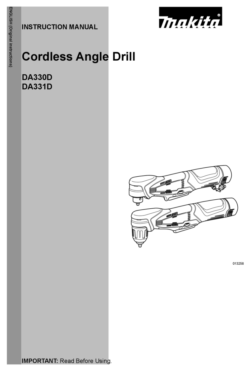
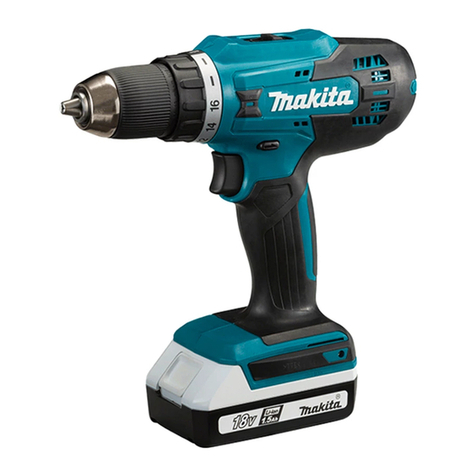
9.6V, 12V, 14.4V Cordless Driver Drills 10mm (3/8")
12V, 14.4V, 18V Cordless Driver Drills 13mm (1/2")
These six tools have been developed as upgraded successors
to the existing Makita tools of Model 6203D series, and features
increased power and enhanced mechanical parts.
One of the remarkable features is the repalceable armature for
reduced repair cost.
Dimensions: mm ( " )
Width ( W )
Height ( H )
Length ( L )
Model No.
233
(9-1/8)
243
(9-9/16)
77
(3)
233
(9-1/8)
243
(9-9/16)
94
(3-11/16)
233
(9-1/8)
247
(9-3/4)
94
(3-11/16)
6207D 6217D 6237D
10mm (3/8")
L
H
W
TECHNICAL INFORMATION
Width ( W )
Height ( H )
Length ( L )
Model No. 6337D 6347D
243
(9-9/16)
94
(3-11/16)
6317D
243
(9-9/16)
247
(9-3/4)
94
(3-11/16)
243
(9-9/16)
251
(9-7/8)
95
(3-3/4)
243
(9-9/16)
13mm (1/2")
Model No. Battery Charger
6207DWDE 9134 (9.6V, 2.6Ah) / 2pcs DC1413
6217DWDE 1234 (12V, 2.6Ah) / 2pcs
6237DWDE 1434 (14.4V, 2.6Ah) / 2pcs DC1413
DC1413
10mm (3/8")
6317DWAE 1222 (12V, 2.0Ah) / 2pcs DC1413
Model No. Battery Charger
6207D 9120, 9122, 9133, 9134, 9135, 9135A DC1413, DC1439, DC1803, DC1822, DC9711
6217D 1220, 1222, 1233, 1234, 1235, 1235A DC1413, DC1439, DC1803, DC1822
6237D 1420, 1422, 1433, 1434, 1435 DC1413, DC1439, DC1803, DC1822
6317D 1220, 1222, 1233, 1234, 1235, 1235A
6337D 1420, 1422, 1433, 1434, 1435 DC1413, DC1439, DC1803, DC1822
6347D 1822, 1833, 1834, 1835 DC1803, DC1822
DC1413, DC1439, DC1803, DC1822
6317DWDE 1234 (12V, 2.6Ah) / 2pcs DC1413
6317DWFE 1235 (12V, 3.0Ah) / 2pcs
6337DWAE 1422 (14.4V, 2.0Ah) / 2pcs DC1413
DC1413
6337DWDE 1434 (14.4V, 2.6Ah) / 2pcs
6337DWFE 1435 (14.4V, 3.0Ah) / 2pcs DC1413
6347DWAE 1822 (18V, 2.0Ah) / 2pcs DC1803
DC1413
6347DWDE 1834 (18V, 2.6Ah) / 2pcs DC1803
6347DWFE 1835 (18V, 3.0Ah) / 2pcs DC1803
Battery
Type
Ni-MH
Ni-MH
Ni-MH
Ni-Cd
Ni-MH
Ni-Cd
Ni-MH
Ni-MH
Ni-Cd
Ni-MH
Ni-MH
Ni-MH
13mm (1/2")
Listed below are variations of these new models.
See page 2.
P 2 / 13
Features and benefits
Change Lever for
Drill/ Screwdriver Mode
New Gear Assembly
Prevents gears from falling out of place.
Prevents clutch from actuating acciden-
tally in drilling mode.
Working mode can be changed
simply by one action.
More Powerful Output
Realized by stronger motor power plus
more efficient power transmission by new
gear assembly
High/ Low
Speed Change Lever
Externally Accessible Brushes
New Separable Type 31 Motor
Palm Fitting Soft Grip
Bit Holder *
For storing a driver bit
Metal Gears for
Enhanced Gear Assembly
For 16 stage torque settings
Adjusting Ring
Model No.
Specification
1 - 6 [10 - 60 / 0.7 - 4.4]
Specification
Voltage (V)
Declutching torque
(N.m [kgf.cm / ft.lbs])
50 [500/ 440]
20 [200/ 180]
60 [600/ 530]
25 [250/ 220]
65 [650/ 580]
30 [300/ 270]Soft joint
Hard joint
Max. fastening torque
(N.m [kgf.cm/ in.lbs])
Electric brake
Net weight with battery: Kg [lbs]
10 mm
6207D 6217D 6237D
9.6 14.412
Yes
Torque settings 16 stages
( + drill mode)
Variable speed control Yes
Mechanical 2-speed Yes
Reverse switch Yes
1.7 [3.7] 1.9 [4.2] 2.0 [4.4]
No load speed
(rpm = min -1)High
Low
0 - 1,300
0 - 400
1 - 10 [1/32 - 3/8]
Chuck capacity (mm [inch])
10 [3/8]
Drilling capacity
(mm [inch]) Wood 25.4 [1] 32 [1-1/4]
1 - 6 [10 - 60 / 0.7 - 4.4]
60 [600/ 530]
25 [250/ 220]
65 [650/ 580]
30 [300/ 270]
80 [800/ 710]
35 [350/ 310]
13 mm
6317D 6337D 6347D
12 1814.4
Yes
16 stages
( + drill mode)
Yes
Yes
Yes
2.0 [4.4] 2.1 [4.6] 2.4 [5.3]
0 - 1,300
0 - 400
1.5 - 13 [1/16 - 1/2]
13 [1/2]
32 [1-1/4]
25.4 [1] 38 [1-1/2]
Steel
1. Uses strong magnet for increased power.
2. Construction without motor case allows;
Light motor body.
Big diameter fan for increased cooling
efficiency
Independently replaceable armature
For controlled operation and
operator comfort
[Model 6207D]
Note: The feature with a mark* is as same as tools of
Model 6203D series.
All the gears in gear assembly are
made of metal.
P 3 / 13
Comparison of products
Model No.
Specification
Net weight (with battery):
kg [lbs]
No load speed
( rpm=min -1 )
High
Low
Dimensions
Length
(mm [inch])
Width
(mm [inch])
Height
(mm [inch])
233
[9-1/8]
77
[3]
243
[9-9/16]
1.7
[3.7]
Makita Competitor A
6207D 6347D
6217D/
6317D 6237D/
6337D 6203D 6343D
6213D/
6313D 6233D
6333D A-9.6 A-18
A-12 A-14.4-0
A-14.4-1
Voltage (V)
Externally accessible
brushes
Soft joint
Hard joint
Max. fastening
torque
(N.m [in.lbs])
Chuck capacity
(mm [inch])
9.6
Aluminum gear housing No
Side grip No
Soft grip handle Yes
0 - 1,300
0 - 400
Torque settings 16 stages +
drill mode
Yes
10 [3/8]
50 [440]
20 [180]
233
[9-1/8]
77
[3]
241
[9-1/2]
1.7
[3.7]
9.6
No
No
No
0 - 1,400
0 - 450
0 - 1,200
0 - 400
0 - 1,300
0 - 400
0 - 1,400
0 - 450
17 stages +
drill mode
Yes
Yes
Yes
No
16 stages +
drill mode
Yes
10 [3/8]
25 [220]
14 [120]
Evaluation on
old standard ----
233 [9-1/8]/
243 [9-9/16]
94
[3-11/16]
243
[9-9/16]
1.9 [4.2]/
2.0 [4.4]
12
10 [3/8]/
13 [1/2]
60 [530]
25 [220]
----
233 [9-1/8]/
243 [9-9/16]
94
[3-11/16]
247
[9-3/4]
2.0 [4.4]/
2.1 [4.6]
14.4
10 [3/8]/
13 [1/2]
65 [580]
30 [270]
----
243
[9-9/16]
95
[3-3/4]
251
[9-7/8]
2.4
[5.3]
18
13 [1/2]
80 [710]
35 [310]
---- 23 [200]
233 [9-1/8]/
243 [9-9/16]
94
[3-11/16]
241
[9-1/2]
1.9 [4.2]/
2.0 [4.4]
12
10 [3/8]/
13 [1/2]
31 [270]
17 [150]
26 [230]
233 [9-1/8]/
243 [9-9/16]
94
[3-11/16]
246
[9-11/16]
2.0 [4.4]/
2.1 [4.6]
14.4
10 [3/8]/
13 [1/2]
35 [310]
22 [200]
31 [275]
255
[10]
95
[3-3/4]
249
[9-3/4]
2.5
[5.5]
18
13 [1/2]
50 [440]
25 [220]
45 [400]
(Not available)
1.5
[3.4]
9.6
No
No
Yes
0 - 1,450
0 - 450
0 - 1,100
0 - 300
23 stages +
drill mode
No
No
No
No
17 stages +
drill mode
No
10 [3/8]
(Not available)
252
[9-7/8]
83
[3-1/4]
235
[9-1/4]
1.9
[4.2]
12
10 [3/8]
38 [340]
20 [180]
35 [310]23 [200]
252
[9-7/8]
83
[3-1/4]
235
[9-1/4]
2.2
[4.9]
14.4
10 [3/8]/
13 [1/2]
41 [360]
22 [200]
38 [334]
252
[9-7/8]
86
[3-3/8]
235
[9-1/4]
2.5
[5.5]
18
13 [1/2]
50 [440]
30 [270]
45 [400]
P 4 / 13
Comparison of products
Test 1: Drilled holes in 38mm (1-1/2") thick Spruce; with 7/8" Spade bit ; on High speed drill mode.
Time Required for Driving a Screw/
Drilling a Hole The Number of Screws Driven/
Holes Drilled on a Single Full-Charge
(Numbers on the bars below are relative values when the capacities of 6203D are indexed at 100.)
9.6V Models
6207D
6203D 100
110 5.9sec
FastSlow
FastSlow
6207D
6203D 2.6Ah 100
2.6Ah 115 50 holes
ManyFew
ManyFew
10050 10050
Test 2: Drove 1/4" x 3" Lag bolts ; into Spruce; on Low speed screwdriver mode.
6207D
6203D 100
95 7.3sec 6207D
6203D 2.6Ah 100
2.6Ah 120 68
screws
10050 10050
Test 2: Drove 1/4" x 3" Lag bolts ; into Spruce; on Low speed screwdriver mode.
Test 1: Drilled holes in 38mm (1-1/2") thick Spruce; with 7/8"Spade bit ; on High speed drill mode.
(Numbers on the bars below are relative values when the capacities of 6313D are indexed at 100.)
12V Models
6317D
6316D 105
6313D 100
120 3.8sec
FastSlow
6317D
6316D 2.6Ah 105
2.6Ah 120 72
holes
ManyFew
10050 10050
6313D 100
2.6Ah
A-12 115
B-1 95
Competitor A
Competitor B
1.7Ah 90
85
2.0Ah
C-1 105
Competitor C
A-12
B-1
Competitor A
Competitor B
C-1
Competitor C
A-12
B-1
Competitor A
Competitor B
C-1
Competitor C
A-12
B-1
Competitor A
Competitor B
C-1
Competitor C
1.7Ah 85
6317D
6316D 100
6313D 100
95 5.9sec
FastSlow
6317D
6316D 2.6Ah 100
2.6Ah 135
95 screws
ManyFew
10050 10050
6313D 100
2.6Ah
100
1.7Ah 85
105
2.0Ah
95 1.7Ah 95
100
P 5 / 13
Time Required for Driving a Screw/
Drilling a Hole The Number of Screws Driven/
Holes Drilled on a Single Full-Charge
Test 2: Drove 1/4" x 3" Lag bolts ; into Spruce; on Low speed screwdriver mode.
(Numbers on the bars below are relative values when the capacities of 6333D are indexed at 100.)
14.4V Models
6317D
6316D 105
6313D 100
105 5.9sec
FastSlow
6317D
6316D 2.6Ah 115
2.6Ah 125 64
holes
ManyFew
10050 10050
6313D 100
2.6Ah
A-12
Competitor B
Competitor B
Competitor A
Competitor A
1.7Ah 90
B-1 95
95
2.0Ah
C-1 105
105
105
Competitor C
C-2
Competitor C
D-1
Competitor D
A-12
Competitor B
Competitor A
B-1
C-1
Competitor C
Test 3: Drilled holes in 38mm (1-1/2") thick Spruce; with 1" Auger bit ; on Low speed drill mode.
1.7Ah
Test 1: Drilled holes in 38mm (1-1/2") thick Spruce; with 7/8" Spade bit ; on High speed drill mode.
6337D
6336D
110
110
6333D 100
100
3.2sec
FastSlow
110
91 screws
ManyFew
10050 10050
100
2.6Ah
A-14.4-0
B-2 Competitor B
Competitor A
C-2
Competitor C
D-1
Competitor D
A-14.4-0
B-2
Competitor B
Competitor A
C-2
Competitor C
D-1
Competitor D
A-14.4-0
B-2 Competitor B
Competitor A
C-2
Competitor C
D-1
Competitor D
A-14.4-0
B-2
115 105
2.4Ah
95
1.7Ah
1.7Ah 75
6337D
6336D
6333D
3.0Ah 110
2.6Ah 110
2.6Ah 110
120
6337D
6336D
110
110
110
6333D 100
90
5.9sec
FastSlow
2.6Ah screws
111
ManyFew
10050 10050
100
2.6Ah
115
2.4Ah
105
2.6Ah
1.7Ah 80
1.7Ah 85
6337D
6336D
6333D
3.0Ah 125
100
100
120
2.6Ah
120
P 6 / 13
Test 3: Drilled holes in 38mm (1-1/2") thick Spruce; with 1" Auger bit ; on Low speed drill mode.
Time Required for Driving a Screw/
Drilling a Hole The Number of Screws Driven/
Holes Drilled on a Single Full-Charge
Test 1: Drilled holes in 38mm (1-1/2") thick Spruce; with 7/8" Spade bit ; on High speed drill mode.
(Numbers on the bars below are relative values when the capacities of 6343D are indexed at 100.)
18V Models
6347D
6343D 100
100
100 2.5sec
FastSlow
2.6Ah 115
2.6Ah
152 holes
ManyFew
10050 10050
95
100
2.4Ah
A-18
85
Competitor A
B-3
Competitor B
A-18
Competitor A
B-3
Competitor B A-18
Competitor A
B-3
Competitor B
A-18
Competitor A
B-3
Competitor B A-18
Competitor A
B-3
Competitor B
A-18
Competitor A
B-3
Competitor B A-18
Competitor A
B-3
Competitor B
A-18
Competitor A
B-3
Competitor B 1.3Ah 40
6347D
6343D
6347D
6343D 100
95
110 4.8sec
FastSlow
2.6Ah 135
2.6Ah 148 screws
ManyFew
10050
10050
100
1.3Ah 45
6347D
6343D
6337D
6336D
110
110
6333D 100
100
5.9sec
FastSlow
2.6Ah holes
79
ManyFew
10050 10050
100
2.6Ah
A-14.4-0 115
Competitor A
B-2
Competitor B
C-2
Competitor C
D-1
Competitor D
A-14.4-0
Competitor A
B-2
Competitor B
C-2
Competitor C
D-1
Competitor D
105
2.4Ah
105
1.7Ah
1.7Ah 85
6337D
6336D
6333D
3.0Ah 115
Test 2: Drove 1/4" x 3" Lag bolts ; into Spruce; on High speed screwdriver mode.
6347D
6343D 100
100
120
120
FastSlow
2.6Ah
78
ManyFew
10050
10050
110
100
2.4Ah
1.3Ah 45
6347D
6343D
Test 3: Drove 3/8" x 3-1/2" Lag bolts ; into Spruce; on Low speed screwdriver mode.
105
105
120
115
2.6Ah
2.6Ah
100
120
95
2.4Ah
2.6Ah screws
6347D
6343D 100
110
110
4.8sec
FastSlow 10050
2.6Ah
138
ManyFew 10050
100
2.4Ah 100
1.3Ah 45
6347D
6343D
Test 4: Drilled holes in 38mm (1-1/2") thick Spruce; with 1" Auger bit ; on Low speed drill mode.
100
125
2.6Ah holes
2.2sec
P 7 / 13
Hint on setting torque
The graph below shows the relation between the torque-setting number on adjusting ring and fastening torque
(= declutching torque), and the chart below the graph shows what number on the adjusting ring is optimum for
the screw to drive. Please refer to them when selecting torque; they will help you choose an optimum
torque-setting number to suit the screw to drive.
(The graph and the chart are available to all tools of Model 6207D series.)
Note: Actual fastening torque is not on the theoretical line of the graph.
Selecting Optimum Torque
Optimum torque can be set for every size of machine screw from M4 to M6.
Wood screws can be driven with their heads flush with each other more precisely than ever even though the
screws vary in thickness or length, or the wood workpieces vary in hardness.
Advantages of 16 Torque Settings
[ft.lbs] (kgf.cm) N.m
[0] (0) 0
[0.7] (10) 1
[1.5] (20) 2
[2.2] (30) 3
[3.0] (40) 4
[3.6] (50) 5
[4.4] (60) 6
[5.1] (70) 7
1 2 4 6 8 10 12 14 16
The Torque-setting Number
on Adjusting Ring
Recommended
Size of Screw
Machine screw M4 M5
ø3.5 x 22
M6
Wood screw
Hard wood
(pine, etc.)
Soft wood
(lauan, etc.)
ø4.1 x 38
ø5.1 x 50
ø5.1 x 50
ø3.5 x 22
ø4.1 x 38
Fastening torque
(Declutching Torque)
Repair P 8 / 13
< 1 > Disassembling of drill chuck See Fig. 1.
For replacing gear assembly, drill chuck has to be disassembled.
Take the following steps.
1. Firmly hold No.1R139 "Drill chuck extractor" with vise.And lock spindle with the drill chuck extractor.
2. Open the jaws of drill chuck fully and take off flat head screw M6 x 22 by turning clockwise.
3. Disassemble drill chuck with hex wrench inserted into drill chuck by turning the hex wrench anti-clockwise.
1R139 Drill chuck extractor Fig. 1 Fig. 1A
If drill chuck is damaged, firmly hold the drill chuck with vise and turn spindle with wrench anti-clockwise
as illustrated in fig. 1A.
< Note >
For replacing other than gear assembly, it is not necessary to disassemble drill chuck.
< 2 > Disassembling housing See Fig. 2.
1. Take off brush holder caps and carbon brushes.
2. Slide mode change lever to the drill mode side.
3. Unscrew the following screws.
* Tapping screw PT 3 x 16 : 9 pcs.
* Pan head screw M 4 x 22 : 1 pc.
Mode change lever
Brush holder cap
Carbon brush
Brush holder cap
Pan head
screw M4 x 22 : 1 pc.
Tapping screw bind
PT 3x16 : 9 pcs.
Carbon brush
Slide mode change lever
to the drill mode side.
Fig. 2
Repair P 9 / 13
< 5 > Assembling change ring
When separating gear assembly from housing, change ring can easily slip off from gear assembly.
Re-assemble change ring to gear assembly as follows.
1. Align the widest bulge of spring holder to the bulge of gear assembly by turning spring holder.
2. Assemble change ring by aligning the bulge of change ring's edge to the portion of gear assembly
marked with circle by the bulge of gear assembly.
Change ring
Bulge of
change ring's edge
Bulge of
change ring's edge
Bulge of
gear assembly
Bulge of
gear assembly
The widest bulge of
spring holder
1
2
3
4
16
15
14
1
2
3
4
16
15
14
< 3 > Disassembling gear assembly and motor section See Fig. 3.
Lifting up mode change lever, separated change ring, gear assembly, yoke, armature and endbell from housing
as a set.
< 4 > Assembling leaf spring See Fig. 5.
Assemble leaf spring to housing L as illustrated in Fig. 4.
Mode change lever
Change ring
Yoke
Armature
Endbell
Gear assembly
Remove as a set without separating from each other.
< Note in disassembling >
Remove so careful that the following springs
do not spring out.
Lock lever
Compression spring 2
Compression spring 2: installed in mode change
lever.
Torsion spring 2: fixing mode change lever
on gear assembly
Mode change lever
Torsion spring 2
Gear assembly
Fig. 3
Fig. 4
Fig. 5
Leaf spring
Housing L
Housing L
Repair P 10 / 13
< 6 > Assembling speed change lever
1. Before assembling, make sure that 2 compression springs are installed in the speed change lever. See fig. 6.
2. Assemble speed change lever to the boss of gear assembly as illustrated in Fig. 6A.
3. After assembling, slide the speed change lever to the change ring side or yoke assembling side
and keep its slid position.
< 7 > Assembling mode change lever and housing
1. Hitch the hook of tension spring 2 to gear assembly and another hook to mode change lever as illustrated in Fig. 7.
2. Assemble mode change lever to gear assembly by inserting the boss of mode change lever into the groove
of gear assembly as illustrated in Fig. 7.
3. Assemble motor section (yoke, armature and endbell) to gear assembly. Assemble them to housing L as illustrated
in Fig. 7A.
Yoke assembling
side
Yoke assembling side
2 compression
springs
Speed change
lever
Boss of
gear assembly
Fig. 6
Fig. 6A
Change ring
side
Change ring
For assembling speed change lever,
approach from yoke assembling side.
And press speed change lever to the
boss of gear assembly.
Tension spring 2 Mode change lever
Fig. 7
Fig. 7A
Aligning the cut portion of
yoke with the boss of housing L,
assemble gear assembly and motor
section to housing L.
Housing L
Motor section
(yoke, armature and endbell)