P 2/ 12
Repair
[3] DISASSEMBLY/ASSEMBLY
[3] -1. Drill chuck
DISASSEMBLING
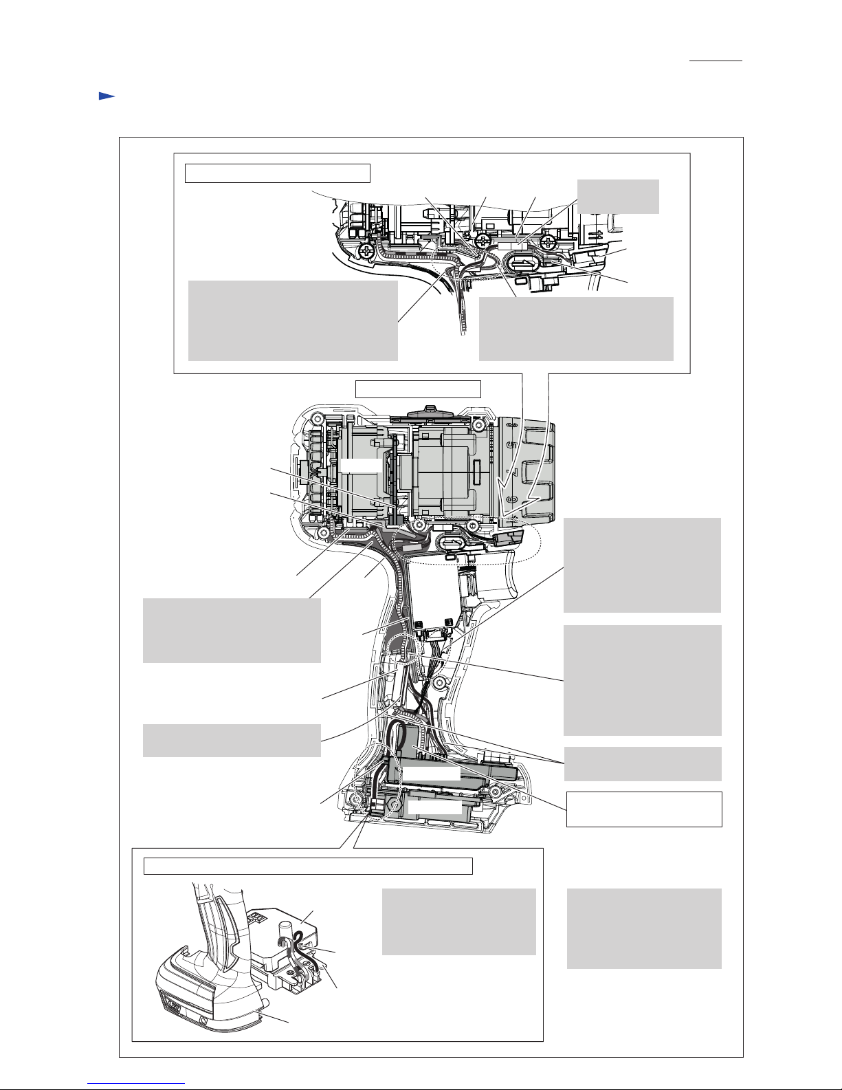
Fig. 1
Fig. 2
4. Set 1R298 to Keyless
drill chuck.
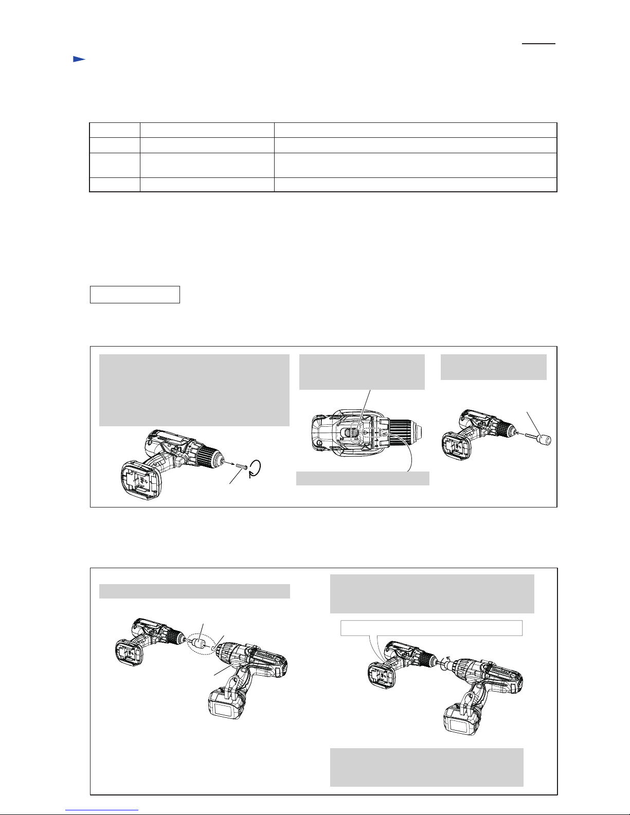
1. Fit Anvil of TW450D to the socket of 1R298.
2. Firmly holding the machine at its grip portion,
remove Keyless drill chuck by driving BTW450
in reverse mode.
Note: Use 1R359 to remove Keyless drill chuck
if it cannot be removed in this step.
See Figs. 6 and 7.
1. Open Drill chuck fully and remove M6x22
Flat head screw by turning it clockwise with
Slotted screwdriver.
Note: Use Impact driver to unscrew M6x22
(-) Flat head screw if it cannot be
removed manually.
M6x22 (-) Flat head screw
(Left handed thread)
(2) For removing Keyless drill chuck, it is necessary to use Impact wrench with strong fastening torque such as
Model BTW450 (440 N.m in max fastening torque).
Remove Drill chuck as drawn in Fig. 2.
(1) Remove M6x22 (-) Flat head screw. Then, preset the machine as drawn in Figs. 1-2 and 1-3. And then, set 1R298 to
the machine. (Fig. 2)
BTW450
Firmly hold the grip portion during the work.
2. Set Speed change lever to
Low speed mode designated
with 1.
1R298
Anvil
1R298
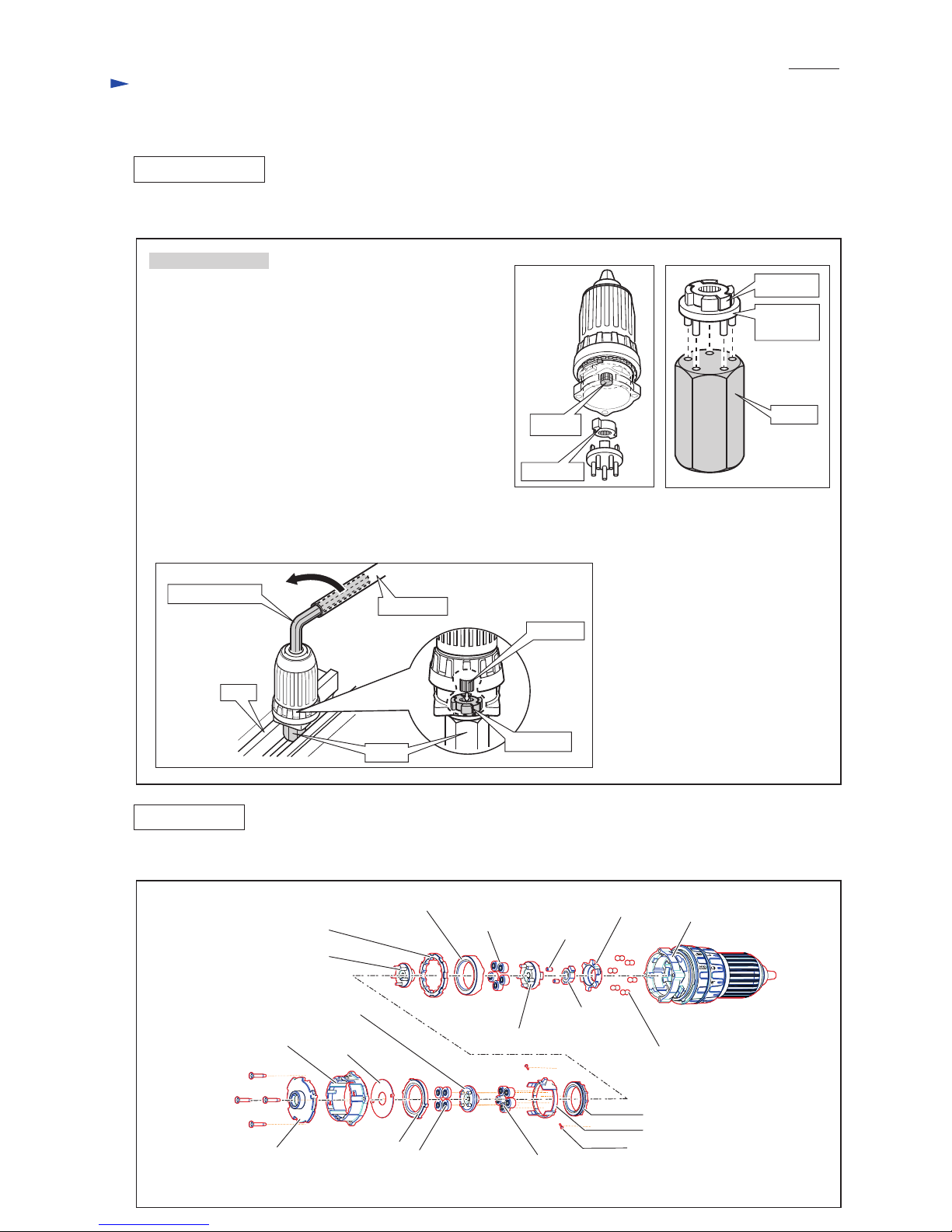
It is not required to lubricate, because this product has gear mechanism of factory assembled.
Code No. Description Use for
1R298 Hex bar 10 with square socket removing Drill chuck
1R359
---
Chuck removing tool removing Drill chuck
(If it is impossible to remove as per the illustration in Figs. 1 and 2.)
Hex wrench 10 removing Drill chuck
[2] LUBRICATION
[1] NECESSARY REPAIRING TOOLS
CAUTION: Repair the machine in accordance with “Instruction manual” or “Safety instructions”.
3. Set Change ring to Drill mode.