Makita DHP481 User manual

1
GB Cordless Hammer Driver Drill INSTRUCTION MANUAL
SI
Akumulatorski udarni vrtalni vijačnik
NAVODILO ZA UPORABO
AL
Trapan me bateri me goditje dhe punto
MANUALI I PËRDORIMIT
BG Акумулаторна ударна бормашина
РЪКОВОДСТВО ЗА ЕКСПЛОАТАЦИЯ
HR Baterijska udarna bušilica-odvijačPRIRUČNIK S UPUTAMA
MK Безжична дупчалка-чекан
У
ПАТСТВО ЗА УПОТРЕБА
RO
Maşinăde găurit şi înşurubat cu acumulatori
MANUAL DE INSTRUCŢIUNI
RS
Бежични ударни бушилица-одвртач
У
ПУТСТВО ЗА УПОТРЕБУ
RUS
Аккумуляторная ударная дрель-шуруповерт
РУКОВОДСТВО ПО ЭКСПЛУАТАЦИИ
UA
Бездротовий дриль зударним приводом
ІНСТРУКЦІЯ ЗЕКСПЛУАТАЦІЇ
DHP481

2
1
2
3
1 014707
1
2 012128
1
2
3 015676
1
4 014696
1
5 014708
1
6 014709
1
AB
7 014703
1
8 014706
1
2
9 014705
12
3
10 014704
1
2
3
4
5
11 014697
1
12 014698

3
1
2
13 014699
12
14 014821
1
23
15 014700
16 014702
1
17 002449

4
ENGLISH (Original instructions)
Explanation of general view
1-1. Red indicator
1-2. Button
1-3. Battery cartridge
2-1. Star marking
3-1. Indicator lamps
3-2. Check button
4-1. LED display
5-1. Switch trigger
6-1. Lamp
7-1. Reversing switch lever
8-1. Speed change lever
9-1. Action mode changing ring
9-2. Arrow
10-1. Adjusting ring
10-2. Graduation
10-3. Arrow
11-1. Protrusion
11-2. Arm
11-3. Groove
11-4. Grip pole
11-5. Side grip
12-1. Sleeve
13-1. Bit holder
13-2. Bit
14-1. Depth rod
14-2. Clamp screw
15-1. Groove
15-2. Hook
15-3. Screw
17-1. Blow-out bulb
SPECIFICATIONS
Model DHP481
Drilling into concrete 16 mm
Drilling into steel 13 mm
Drilling into wood 76 mm
Fastening wood screw 10 mm x 90 mm
Capacities
Fastening machine screw 6 mm
High (2) 0 - 2,100
No load speed (min-1) Low (1) 0 - 550
High (2) 0 - 31,500
Blows per minute Low (1) 0 - 8,250
Overall length 205 mm
Net weight 2.7 kg
Rated voltage D.C. 18 V
• Due to our continuing program of research and development, the specifications herein are subject to change without notice.
• Specifications and battery cartridge may differ from country to country.
• Weight, with battery cartridge, according to EPTA-Procedure 01/2003
ENE079-1
Intended use
The tool is intended for impact drilling in brick, concrete
and stone. It is also suitable for screw driving and
drilling without impact in wood, metal, ceramic and
plastic.
ENG905-1
Noise
The typical A-weighted noise level determined
according to EN60745:
Sound pressure level (LpA) : 85 dB (A)
Sound power level (LWA) : 96 dB (A)
Uncertainty (K) : 3 dB (A)
Wear ear protection
ENG900-1
Vibration
The vibration total value (tri-axial vector sum)
determined according to EN60745:
Work mode: impact drilling into concrete
Vibration emission (ah,ID) : 6.5 m/s2
Uncertainty (K) : 1.5 m/s2
Work mode: drilling into metal
Vibration emission (ah,D) : 2.5 m/s2or less
Uncertainty (K) : 1.5 m/s2
ENG901-1
• The declared vibration emission value has been
measured in accordance with the standard test
method and may be used for comparing one tool
with another.
• The declared vibration emission value may also be
used in a preliminary assessment of exposure.
WARNING:
• The vibration emission during actual use of the
power tool can differ from the declared emission
value depending on the ways in which the tool is
used.
• Be sure to identify safety measures to protect the
operator that are based on an estimation of
exposure in the actual conditions of use (taking
account of all parts of the operating cycle such as
the times when the tool is switched off and when it
is running idle in addition to the trigger time).

5
ENH101-18
For European countries only
EC Declaration of Conformity
Makita declares that the following Machine(s):
Designation of Machine:
Cordless Hammer Driver Drill
Model No./ Type: DHP481
Conforms to the following European Directives:
2006/42/EC
They are manufactured in accordance with the following
standard or standardized documents:
EN60745
The technical file in accordance with 2006/42/EC is
available from:
Makita, Jan-Baptist Vinkstraat 2, 3070, Belgium
22.8.2013
000331
Yasushi Fukaya
Director
Makita, Jan-Baptist Vinkstraat 2, 3070, Belgium
GEA010-1
General Power Tool Safety
Warnings
WARNING Read all safety warnings and all
instructions. Failure to follow the warnings and
instructions may result in electric shock, fire and/or
serious injury.
Save all warnings and instructions for
future reference.
GEB056-5
CORDLESS HAMMER DRIVER
DRILL SAFETY WARNINGS
1. Wear ear protectors when impact drilling.
Exposure to noise can cause hearing loss.
2. Use auxiliary handle(s), if supplied with the
tool. Loss of control can cause personal injury.
3. Hold power tool by insulated gripping
surfaces, when performing an operation
where the cutting accessory may contact
hidden wiring. Cutting accessory contacting a
"live" wire may make exposed metal parts of the
power tool "live" and could give the operator an
electric shock.
4. Hold power tool by insulated gripping
surfaces, when performing an operation
where the fastener may contact hidden wiring.
Fasteners contacting a "live" wire may make
exposed metal parts of the power tool "live" and
could give the operator an electric shock.
5. Always be sure you have a firm footing.
Be sure no one is below when using the tool
in high locations.
6. Hold the tool firmly.
7. Keep hands away from rotating parts.
8. Do not leave the tool running. Operate the tool
only when hand-held.
9. Do not touch the bit or the workpiece
immediately after operation; they may be
extremely hot and could burn your skin.
10. Some material contains chemicals which may
be toxic. Take caution to prevent dust
inhalation and skin contact. Follow material
supplier safety data.
SAVE THESE INSTRUCTIONS.
WARNING:
DO NOT let comfort or familiarity with product
(gained from repeated use) replace strict adherence
to safety rules for the subject product. MISUSE or
failure to follow the safety rules stated in this
instruction manual may cause serious personal
injury.
ENC007-9
IMPORTANT SAFETY
INSTRUCTIONS
FOR BATTERY CARTRIDGE
1. Before using battery cartridge, read all
instructions and cautionary markings on (1)
battery charger, (2) battery, and (3) product
using battery.
2. Do not disassemble battery cartridge.
3. If operating time has become excessively
shorter, stop operating immediately. It may
result in a risk of overheating, possible burns
and even an explosion.
4. If electrolyte gets into your eyes, rinse them
out with clear water and seek medical
attention right away. It may result in loss of
your eyesight.
5. Do not short the battery cartridge:
(1) Do not touch the terminals with any
conductive material.
(2) Avoid storing battery cartridge in a
container with other metal objects such
as nails, coins, etc.
(3) Do not expose battery cartridge to water
or rain.
A battery short can cause a large current flow,
overheating, possible burns and even a
breakdown.
6. Do not store the tool and battery cartridge in
locations where the temperature may reach or
exceed 50 ゚C (122 ゚F).

6
7. Do not incinerate the battery cartridge even if
it is severely damaged or is completely worn
out. The battery cartridge can explode in a fire.
8. Be careful not to drop or strike battery.
9. Do not use a damaged battery.
10. Follow your local regulations relating to
disposal of battery.
SAVE THESE INSTRUCTIONS.
Tips for maintaining maximum battery life
1. Charge the battery cartridge before
completely discharged.
Always stop tool operation and charge the
battery cartridge when you notice less tool
power.
2. Never recharge a fully charged battery
cartridge.
Overcharging shortens the battery service life.
3. Charge the battery cartridge with room
temperature at 10 ゚C - 40 ゚C (50 ゚F - 104 ゚F).
Let a hot battery cartridge cool down before
charging it.
4. Charge the battery cartridge if you do not use
it for a long period (more than six months).
FUNCTIONAL DESCRIPTION
CAUTION:
• Always be sure that the tool is switched off and the
battery cartridge is removed before adjusting or
checking function on the tool.
Installing or removing battery cartridge
Fig.1
CAUTION:
• Always switch off the tool before installing or
removing of the battery cartridge.
•
Hold the tool and the battery cartridge firmly when
installing or removing battery cartridge.
Failure to
hold the tool and the battery cartridge firmly may cause
them to slip off your hands and result in damage to the
tool and battery cartridge and a personal injury.
To remove the battery cartridge, slide it from the tool
while sliding the button on the front of the cartridge.
To install the battery cartridge, align the tongue on the
battery cartridge with the groove in the housing and slip
it into place. Insert it all the way until it locks in place
with a little click. If you can see the red indicator on the
upper side of the button, it is not locked completely.
CAUTION:
• Always install the battery cartridge fully until the
red indicator cannot be seen. If not, it may
accidentally fall out of the tool, causing injury to
you or someone around you.
• Do not install the battery cartridge forcibly. If the
cartridge does not slide in easily, it is not being
inserted correctly.
Battery protection system
(Lithium-ion battery with star marking)
Fig.2
Lithium-ion batteries with a star marking are equipped
with a protection system. This system automatically cuts
off power to the tool to extend battery life.
The tool will automatically stop during operation if the
tool and/or battery are placed under one of the following
conditions:
• Overloaded:
The tool is operated in a manner that causes
it to draw an abnormally high current.
In this situation, release the switch trigger on
the tool and stop the application that caused
the tool to become overloaded. Then pull the
switch trigger again to restart.
If the tool does not start, the battery is
overheated. In this situation, let the battery
cool before pulling the switch trigger again.
• Low battery voltage:
The remaining battery capacity is too low
and the tool will not operate. In this situation,
remove and recharge the battery.

7
Indicating the remaining battery capacity
(Only for battery cartridges with "B" at the end of the
model number.)
Fig.3
Press the check button on the battery cartridge to
indicate the remaining battery capacity. The indicator
lamps light up for few seconds.
Off BlinkingLighted
Indicator lamps
Charge the
battery.
0% to 25%
25% to 50%
50% to 75%
75% to 100%
Remaining
capacity
The battery
may have
malfunctioned.
015658
NOTE:
• Depending on the conditions of use and the
ambient temperature, the indication may differ
slightly from the actual capacity.
Indicating the remaining battery capacity
(Country specific)
Fig.4
When you pull the switch trigger, the LED display shows
the remaining battery capacity as the following table.
LED indicator status Remaining battery capacity
About 50% or more
About 20% - 50%
About less than 20%
013980
NOTE:
• The LED display goes off approximately one
minute after releasing the switch trigger to save
the battery power. To check the remaining battery
capacity, slightly pull the switch trigger.
• When the LED display lights up but the tool does
not work even with a recharged battery cartridge,
cool down the tool fully. If the condition does not
change, have the tool repaired by a Makita local
service center.
Switch action
CAUTION:
• Before installing the battery cartridge into the tool,
always check to see that the switch trigger
actuates properly and returns to the "OFF"
position when released.
Fig.5
To start the tool, simply pull the switch trigger. Tool
speed is increased by increasing pressure on the switch
trigger. Release the switch trigger to stop.
Lighting up the front lamp
Fig.6
CAUTION:
• Do not look in the light or see the source of light
directly.
Pull the switch trigger to light up the lamp. The lamp
keeps on lighting while the switch trigger is being pulled.
The lamp goes out 10 -15 seconds after releasing the
trigger.
NOTE:
• When the tool is overheated, the tool stops
automatically and the lamp starts flashing. In this
case, release the switch trigger. The lamp turns off
in one minute.
• Use a dry cloth to wipe the dirt off the lens of lamp.
Be careful not to scratch the lens of lamp, or it
may lower the illumination.
Reversing switch action
CAUTION:
• Always check the direction of rotation before
operation.
• Use the reversing switch only after the tool comes
to a complete stop. Changing the direction of
rotation before the tool stops may damage the tool.
• When not operating the tool, always set the
reversing switch lever to the neutral position.
Fig.7
This tool has a reversing switch to change the direction
of rotation. Depress the reversing switch lever from the
A side for clockwise rotation or from the B side for
counterclockwise rotation.
When the reversing switch lever is in the neutral
position, the switch trigger cannot be pulled.

8
Speed change
CAUTION:
• Always set the speed change lever fully to the
correct position. If you operate the tool with the
speed change lever positioned halfway between
the "1" side and, "2" side, the tool may be
damaged.
• Do not use the speed change lever while the tool
is running. The tool may be damaged.
Fig.8
To change the speed, first switch off the tool and then
slide the speed change lever to the "2" side for high
speed or, "1" side for low speed. Be sure that the speed
change lever is set to the correct position before
operation. Use the right speed for your job.
Selecting the action mode
CAUTION:
• Always set the ring correctly to your desired mode
mark. If you operate the tool with the ring
positioned halfway between the mode marks, the
tool may be damaged.
Fig.9
This tool employs an action mode changing ring. Select
one of the three modes suitable for your work needs by
using this ring.
For rotation only, turn the ring so that the arrow on the
tool body points toward the mark on the ring.
For rotation with hammering, turn the ring so that the
arrow points toward the mark on the ring.
For rotation with clutch, turn the ring so that the arrow
points toward the mark on the ring.
Adjusting the fastening torque
(screwdriver mode " ")
Fig.10
The fastening torque can be adjusted in 21 steps by
turning the adjusting ring so that its graduations are
aligned with the pointer on the tool body.
First, slide the action mode change lever to the position
of symbol.
The fastening torque is minimum when the number 1 is
aligned with the pointer, and maximum when the
marking is aligned with the pointer. The clutch will slip at
various torque levels when set at the number 1 to 21.
Before actual operation, drive a trial screw into your
material or a piece of duplicate material to determine
which torque level is required for a particular application.
NOTE:
• The adjusting ring does not lock when the pointer
is positioned only halfway between the
graduations.
ASSEMBLY
CAUTION:
• Always be sure that the tool is switched off and the
battery cartridge is removed before carrying out
any work on the tool.
Installing side grip (auxiliary handle)
Fig.11
Always use the side grip to ensure operating safety.
Insert the side grip so that the groove on the arm fit in
one of the counter parts on the tool. Then tighten the
grip by turning clockwise.
Depending the operations, you can install the side grip
either right or left side of the tool.
Installing or removing driver bit or drill bit
Fig.12
Turn the sleeve counterclockwise to open the chuck
jaws. Place the bit in the chuck as far as it will go. Turn
the sleeve clockwise to tighten the chuck. To remove
the bit, turn the sleeve counterclockwise.
Installing bit holder
Fig.13
Fit the bit holder into the protrusion at the tool foot on
either right or left side and secure it with a screw.
When not using the driver bit, keep it in the bit holders.
Bits 45 mm long can be kept there.
Adjustable depth rod
Fig.14
The adjustable depth rod is used to drill holes of uniform
depth. Loosen the clamp screw, set to desired position,
then tighten the clamp screw.
Hook
Fig.15
The hook is convenient for temporarily hanging the tool.
This can be installed on either side of the tool.
To install the hook, insert it into a groove in the tool
housing on either side and then secure it with a screw.
To remove, loosen the screw and then take it out.
OPERATION
Fig.16
Hammer drilling operation
CAUTION:
•
There is a tremendous and sudden twisting force
exerted on the tool/bit at the time of hole break-through,
when the hole becomes clogged with chips and particles,
or when striking reinforcing rods embedded in the
concrete. Always use the side grip (auxiliary handle) and
firmly hold the tool by both side grip and switch handle
during operations. Failure to do so may result in the loss
of control of the tool and potentially severe injury.

9
First, slide the action mode change lever so that it
points to the marking. The adjusting ring can be
aligned in any torque levels for this operation.
Be sure to use a tungsten-carbide tipped bit.
Position the bit at the desired location for the hole, then
pull the switch trigger. Do not force the tool. Light
pressure gives best results. Keep the tool in position
and prevent it from slipping away from the hole.
Do not apply more pressure when the hole becomes
clogged with chips or particles. Instead, run the tool at
an idle, then remove the bit partially from the hole. By
repeating this several times, the hole will be cleaned out
and normal drilling may be resumed.
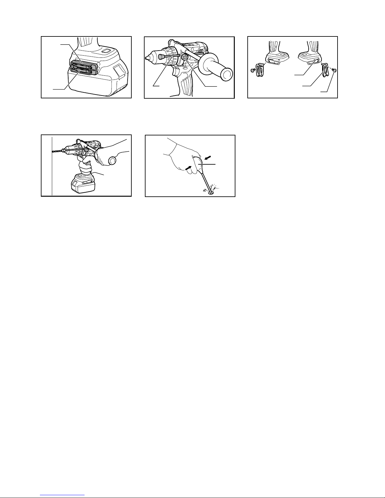
Blow-out bulb (optional accessory)
Fig.17
After drilling the hole, use the blow-out bulb to clean the
dust out of the hole.
Screwdriving operation
First, slide the action mode change lever so that it points
to the marking. Adjust the adjusting ring to the proper
torque level for your work. Then proceed as follows.
Place the point of the driver bit in the screw head and
apply pressure to the tool. Start the tool slowly and then
increase the speed gradually. Release the switch trigger
as soon as the clutch cuts in.
NOTE:
• Make sure that the driver bit is inserted straight in
the screw head, or the screw and/or bit may be
damaged.
• When driving wood screw, predrill a pilot hole 2/3
the diameter of the screw. It makes driving easier
and prevents splitting of the workpiece.
• If the tool is operated continuously until the battery
cartridge has discharged, allow the tool to rest for
15 minutes before proceeding with a fresh battery.
Drilling operation
CAUTION:
•
Pressing excessively on the tool will not speed up the
drilling. In fact, this excessive pressure will only serve
to damage the tip of your bit, decrease the tool
performance and shorten the service life of the tool.
• There is a tremendous force exerted on the tool/bit
at the time of hole break through. Hold the tool
firmly and exert care when the bit begins to break
through the workpiece.
• A stuck bit can be removed simply by setting the
reversing switch to reverse rotation in order to
back out. However, the tool may back out abruptly
if you do not hold it firmly.
• Always secure small workpieces in a vise or
similar hold-down device.
• If the tool is operated continuously until the battery
cartridge has discharged, allow the tool to rest for
15 minutes before proceeding with a fresh battery.
First, slide the action mode change lever so that it
points to the marking. The adjusting ring can be
aligned in any torque levels for this operation. Then
proceed as follows.
Drilling in wood
When drilling in wood, the best results are obtained with
wood drills equipped with a guide screw. The guide
screw makes drilling easier by pulling the bit into the
workpiece.
Drilling in metal
To prevent the bit from slipping when starting a hole,
make an indentation with a center-punch and hammer
at the point to be drilled. Place the point of the bit in the
indentation and start drilling.
Use a cutting lubricant when drilling metals. The
exceptions are iron and brass which should be drilled dry.
MAINTENANCE
CAUTION:
• Always be sure that the tool is switched off and the
battery cartridge is removed before attempting to
perform inspection or maintenance.
• Never use gasoline, benzine, thinner, alcohol or
the like. Discoloration, deformation or cracks may
result.
To maintain product SAFETY and RELIABILITY, repairs,
any other maintenance or adjustment should be
performed by Makita Authorized Service Centers,
always using Makita replacement parts.
OPTIONAL ACCESSORIES
CAUTION:
•
These accessories or attachments are recommended
for use with your Makita tool specified in this manual.
The use of any other accessories or attachments
might present a risk of injury to persons. Only use
accessory or attachment for its stated purpose.
If you need any assistance for more details regarding
these accessories, ask your local Makita Service Center.
• Drill bits
• Hammer drill bits
• Screw bits
• Blow-out bulb
• Makita genuine battery and charger
• Grip assembly
• Depth rod
• Hook
• Rubber pad assembly
• Wool bonnet
• Foam polishing pad
NOTE:
• Some items in the list may be included in the tool
package as standard accessories. They may differ
from country to country.

10
SLOVENŠČINA (izvirna navodila)
Razlaga splošnega pogleda
1-1. Rdeči indikator
1-2. Gumb
1-3. Baterijski vložek
2-1. Oznaka z zvezdico
3-1. Indikatorske lučke
3-2. Gumb CHECK
4-1. LED zaslon
5-1. Sprožilno stikalo
6-1. Svetilka
7-1. Preklopna ročica za obratno smer
8-1. Ročica za spremembo hitrosti
9-1. Obročza spremembo načina
delovanja
9-2. Puščica
10-1. Nastavljalni obroč
10-2. Lestvica
10-3. Puščica
11-1. Izbočenje
11-2. Roka
11-3. Utor
11-4. Držalna palica
11-5. Stranski ročaj
12-1. Vložek
13-1. Držalo nastavkov
13-2. Nastavek
14-1. Globinski drog
14-2. Vpenjalni vijak
15-1. Utor
15-2. Kljuka
15-3. Vijak
17-1. Ročka za izpihovanje
TEHNIČNI PODATKI
Model DHP481
Vrtanje v beton 16 mm
Vrtanje v jeklo 13 mm
Vrtanje v les 76 mm
Pritrdilni lesni vijak 10 mm x 90 mm
Zmogljivosti
Pritrdilni strojni vijak 6 mm
Visoko (2) 0 - 2.100
Hitrost brez obremenitve (min
-1
)
Nizko (1) 0 - 550
Visoko (2) 0 - 31.500
Udarci na minuto Nizko (1) 0 - 8.250
Skupna dolžina 205 mm
Neto teža 2,7 kg
Nazivna napetost D.C. 18 V
• Zaradi našega nenehnega programa raziskav in razvoja si pridržujemo pravico do spremembe tehničnih podatkov brez obvestila.
• Tehnični podatki in baterijski vložki se lahko razlikujejo od države do države.
• Teža z baterijskim vložkom je v skladu z EPTA-postopkom 01/2003
ENE079-1
Namen uporabe
Orodje je namenjeno za vrtanje v opeko, beton in
kamen. Prav tako je primerno za vijačenje in vrtanje
brez udarjanja v les, kovino, keramiko in plastiko.
ENG905-1
Hrup
Tipični, z A ocenjeni vrednosti hrupa glede na EN60745:
Raven zvočnega tlaka (LpA): 85 dB (A)
Raven zvočne moči (LWA): 96 dB (A)
Odstopanje (K): 3 dB (A)
Uporabljajte zaščito za sluh
ENG900-1
Vibracije
Skupne vrednosti vibracij (vektorska vsota treh osi) po
EN60745:
Delovni način: udarno vrtanje v beton
Oddajanje tresljajev (ah,ID): 6,5 m/s2
Odstopanje (K): 1,5 m/s2
Delovni način: vrtanje v kovino
Oddajanje tresljajev (ah,D): 2,5 m/s2ali manj
Odstopanje (K): 1,5 m/s2
ENG901-1
•
Navedena vrednost oddajanja vibracij je bila
izmerjena v skladu s standardnimi metodami
testiranja in se lahko uporablja za primerjavo orodij.
• Navedena vrednost oddajanja vibracij se lahko
uporablja tudi pri predhodni oceni izpostavljenosti.
OPOZORILO:
•
Oddajanje vibracij med dejansko uporabo električnega
orodja se lahko razlikuje od navedene vrednosti
oddajanja, odvisno od načina uporabe orodja.
• Upravljavec mora za lastno zaščito poznati
varnostne ukrepe, ki temeljijo na oceni
izpostavljenosti v dejanskih pogojih uporabe
(upoštevajočceloten delovni proces v trenutkih, ko
je orodje izključeno in ko deluje v prostem teku z
dodatkom časa sprožitve).

11
ENH101-18
Samo za evropske države
ES Izjava o skladnosti
Družba Makita izjavlja, da je/so naslednji stroj/-i:
Oznaka stroja:
Akumulatorski udarni vrtalni vijačnik
Model št./vrsta: DHP481
Je skladen z naslednjimi evropskimi direktivami:
2006/42/ES
Izdelan v skladu z naslednjim standardom ali
standardiziranimi dokumenti:
EN60745
Tehnična dokumentacija v skladu z direktivo
2006/42/ES je na voljo na:
Makita, Jan-Baptist Vinkstraat 2, 3070, Belgija
22.8.2013
000331
Yasushi Fukaya
Direktor
Makita, Jan-Baptist Vinkstraat 2, 3070, Belgija
GEA010-1
Splošna varnostna opozorila za
električno orodje
OPOZORILO Preberite vsa varnostna opozorila
in navodila. Neupoštevanje opozoril in navodil lahko
vodi do električnega udara, požara, in/ali hudih telesnih
poškodb.
Shranite vsa opozorila in navodila za
kasnejšo uporabo.
GEB056-5
VARNOSTNA OPOZORILA ZA
BREZŽIČNI UDARNI VIJAČNIK IN
VRTALNIK
1. Pri udarnem vrtanju nosite zaščito za sluh.
Izpostavljenost hrupu lahko povzroči izgubo sluha.
2. Uporabite pomožne ročaje, če so dobavljeni z
orodjem. Izguba nadzora lahko povzroči
poškodbe oseb.
3. Če obstaja nevarnost, da bi z rezilnim orodjem
prerezali skrito električno napeljavo, držite
električno orodje na izoliranih držalnih
površinah. Ob stiku z vodniki pod napetostjo
dobijo napetost vsi neizolirani kovinski deli
električnega orodja, zaradi česar lahko pride do
električnega udara.
4. Če obstaja nevarnost, da bi s pritrjevalnikom
prerezali skrito električno napeljavo, držite
električno orodje na izoliranih držalnih
površinah. Ob stiku z vodniki pod napetostjo
dobijo napetost vsi neizolirani kovinski deli
električnega orodja, zaradi česar lahko pride do
električnega udara.
5. Vedno zagotovite, da imate trden oprijem na
podlagi, kjer stojite.
Kadar uporabljate orodje na višini, se
prepričajte, da spodaj ni nikogar.
6. Trdno držite orodje.
7. Ne približujte rok vrtečim se delom.
8. Orodja ne pustite delovati brez nadzora.
Dovoljeno ga je uporabljati samo ročno.
9. Takoj po končani obdelavi se ne dotikajte
nastavka ali obdelovanca; lahko sta zelo
vroča in povzročita opekline kože.
10. Nekateri materiali vsebujejo kemikalije, ki so
lahko strupene. Bodite previdni in preprečite
vdihavanje prahu in stik s kožo. Upoštevajte
varnostne podatke dobavitelja materiala.
SHRANITE TA NAVODILA.
OPOZORILO:
NE dopustite si, da bi zaradi udobnejšega dela ali
poznavanja izdelka (pridobljenega z večkratno
uporabo) opustili striktno upoštevanje varnostnih
pravil pri uporabi stroja. ZLORABA ali
neupoštevanje varnostnih pravil v teh navodilih za
uporabo lahko povzroči hude telesne poškodbe.
ENC007-9
POMEMBNA VARNOSTNA
NAVODILA
ZA BATERIJSKE VLOŽKE
1. Pred uporabo baterijskega vložka preberite
vsa navodila in opozorilne oznake na (1)
polnilniku akumulatorja, (2) akumulatorju in
(3) izdelku, ki uporablja akumulator.
2. Ne razstavljajte baterijskega vložka.
3. Če se je čas delovanja občutno skrajšal, takoj
prekinite z uporabo. V nasprotnem primeru je
lahko rezultat pregretje, morebitne opekline in
celo eksplozija.
4. Če pride elektrolit v oči, jih sperite s čisto
vodo in takoj poiščite zdravniško pomoč.
Posledica je lahko izguba vida.
5. Ne povzročite kratkega stika baterijskega
vložka:
(1) Ne dotikajte se priključkov s kakršnim
koli prevodnim materialom.
(2) Izogibajte se shranjevanju baterijskega
vložka v posodo z drugimi kovinskimi
predmeti kot so žeblji, kovanci itn.
(3) Ne izpostavljajte baterijskega vložka vodi
ali dežju.

12
Kratek stik akumulatorja lahko povzroči velik
tok, pregretje, morebitne opekline in celo
eksplozijo.
6. Ne shranjujte orodja in baterijskega vložka na
lokacijah, kjer lahko temperatura doseže ali
preseže 50 ゚C (122 ゚F).
7. Ne sežigajte baterijskega vložka, tudi če je
hudo poškodovan ali v celoti izpraznjen.
Baterijski vložek lahko v ognju eksplodira.
8. Bodite previdni, da vam akumulator ne pade
in ga ne udarjajte.
9. Ne uporabljajte poškodovanih akumulatorjev.
10. Upoštevajte lokalne uredbe glede odlaganja
akumulatorja.
SHRANITE TA NAVODILA.
Nasveti za maksimalno življenjsko dobo
akumulatorja
1. Napolnite baterijski vložek preden se v celoti
izprazni.
Ko opazite, da ima orodje manjšo moč, vedno
ustavite delovanje orodja in napolnite
baterijski vložek.
2. Nikoli znova ne polnite popolnoma
napolnjenega baterijskega vložka.
Prenapolnjenje skrajša življenjsko dobo
akumulatorja.
3. Napolnite baterijski vložek pri sobni
temperaturi med 10 ゚C in 40 ゚C (50 ゚F - 104 ゚
F). Počakajte, da se vročbaterijski vložek
pred polnjenjem ohladi.
4. Akumulatorsko baterijo napolnite, če je ne
uporabljate dalj časa (dlje kot šest mesecev).
OPIS DELOVANJA
POZOR:
• Pred vsako nastavitvijo ali pregledom delovanja
orodja se prepričajte, da je le to izključeno in da je
akumulatorska baterija odstranjena.
Nameščanje ali odstranjevanje
akumulatorske baterije
Sl.1
POZOR:
• Vedno izklopite orodje, preden namestite ali
odstranite akumulatorsko baterijo.
•
Kadar nameščate ali odstranjujete akumulatorsko
baterijo, trdno držite orodje in akumulatorsko
baterijo.
Če orodja in akumulatorske baterije ne držite
trdno, se lahko zgodi, da vam zdrsneta iz rok,
posledica pa je poškodba orodja in akumulatorske
baterije ter telesna poškodba.
Za odstranitev akumulatorske baterije iz orodja jo
premaknite iz orodja, ob tem pa premaknite gumb na
sprednji strani akumulatorske baterije.
Pri vstavljanju akumulatorske baterije poravnajte jeziček
na akumulatorski bateriji z utorom na ohišju in ga
potisnite v ležišče. Akumulatorsko baterijo vstavite do
konca, da se razločno zaskoči. Če vidite rdeči indikator
na zgornji strani gumba, ta ni popolnoma zaklenjen.
POZOR:
• Vedno namestite akumulatorsko baterijo, tako da
rdeči indikator ni večviden. Če tega ne upoštevate,
lahko akumulator nepričakovano izpade iz orodja
in poškoduje vas ali osebe v neposredni bližini.
• Ne nameščajte akumulatorske baterije s silo. Če
se akumulatorska baterija ne zaskoči zlahka, ni
pravilno vstavljena.
Sistem za zaščito akumulatorja
(litij-ionske akumulatorji z zvezdico)
Sl.2
Litij-ionske akumulatorji so opremljene z zaščitnim sistemom.
Ta sistem samodejno izklopi dovajanje električne energije v
orodje, da bi podaljšal življenjsko dobo baterije.
Orodje se bo samodejno zaustavilo med delovanjem, če sta
orodje in/ali baterija zamenjana pod naslednjimi pogoji:
• Preobremenjeno:
Orodje deluje na način, ki povzroča, da
povleče nenormalno visok tok.
V takem primeru sprostite sprožilno stikalo
na orodju in ga prenehajte uporabljati na
način, zaradi katerega je prišlo do
preobremenitve. Nato znova povlecite
sprožilno stikalo, da ga zaženete.
Če se orodje ne zažene, je akumulator
pregret. V tem primeru pustite, da se
akumulator ohladi, preden znova pritisnete
sprožilno stikalo.

13
• Nizka napetost akumulatorja:
Preostala zmogljivost akumulatorja je
prenizka in orodje ne bo delovalo. V tem
primeru odstranite in napolnite akumulator.
Prikazuje preostalo zmogljivost akumulatorja
(Samo za akumulatorske baterije z oznako »B« na
koncu številke modela.)
Sl.3
Pritisnite gumb za preverjanje napolnjenosti na
akumulatorski bateriji, da preverite preostalo zmogljivost.
Indikatorske lučke zasvetijo za nekaj sekund.
Ne sveti UtripaSveti
Indikatorske lučke
Napolnite
akumulator.
od 0 % do 25 %
od 25 % do 50 %
od 50 % do 75 %
od 75 % do 100 %
Preostala
zmogljivost
Akumulator
je morda
okvarjen.
015658
OPOMBA:
• Odvisno od pogojev uporabe in okoljske
temperature se označba lahko nekoliko razlikuje
od dejanske napolnjenosti.
Prikazuje preostalo zmogljivost akumulatorja
(Odvisno od države)
Sl.4
Ko povlečete sprožilno stikalo, se na LED zaslonu
prikaže preostala zmogljivost akumulatorja v skladu z
naslednjo tabelo.
status LED indikatorja Preostala zmogljivost
akumulatorja
približno 50 % ali več
približno 20 - 50 %
približno manj kot 20 %
013980
OPOMBA:
• Približno eno minuto po tem, ko spustite sprožilno
stikalo, LED zaslon ugasne, da varčuje z
akumulatorjem. Če želite preveriti preostalo
zmogljivost akumulatorja, rahlo povlecite sprožilno
stikalo.
• Če se LED zaslon osvetli, vendar orodje ne deluje,
tudi če je akumulatorska baterija napolnjena,
najprej popolnoma ohladite orodje. Če se stanje
ne spremeni, naj orodje popravi lokalni servisni
center Makita.
Delovanje stikala
POZOR:
• Preden namestite akumulatorsko baterijo v orodje
se vedno prepričajte, da je stikalo brezhibno in da
se vrača v položaj za izklop (OFF), ko ga spustite.
Sl.5
Za zagon orodja povlecite sprožilno stikalo. Hitrost
orodja se poveča za povečani tlak na sprožilnem stikalu.
Za izklop orodja spustite sprožilno stikalo.
Vklop sprednje lučke
Sl.6
POZOR:
• Ne glejte neposredno v lučko ali vir svetlobe.
Povlecite sprožilno stikalo za vklop svetilke. Svetilka
sveti, dokler je pritisnjeno sprožilno stikalo. Svetilka
ugasne 10 - 15 sekund zatem, ko spustite sprožilno
stikalo.
OPOMBA:
• Če je orodje pregreto, se samodejno ustavi in
lučka začne utripati. V tem primeru izpustite
sprožilno stikalo. Lučka ugasne v eni minuti.
• Umazanijo na steklu lučke obrišite s suho krpo.
Pazite, da ne opraskate stekla lučke, ker praske
občutno zmanjšajo svetilnost.
Stikalo za preklop smeri vrtenja
POZOR:
• Pred obratovanjem vedno preverite smer vrtenja.
• Stikalo za spreminjanje smeri vrtenja uporabite
šele, ko se stroj popolnoma ustavi. Če smer
vrtenja spremenite, preden se stroj ustavi, se ta
lahko poškoduje.
• Ko orodja ne uporabljate, vedno potisnite
preklopno stikalo v nevtralen položaj.
Sl.7
To orodje je opremljeno s preklopnikom za spremembo
smeri vrtenja. Ročico preklopnika smeri vrtenja pritisnite
v smeri A za vrtenje v smeri urinega kazalca in v smeri
B za vrtenje v obratni smeri urinega kazalca.
Ko je preklopno stikalo v nevtralnem položaju, se
glavnega stikala ne da premakniti.

14
Spreminjanje hitrosti
POZOR:
• Ročico za spremembo hitrosti vedno potisnite do
konca v pravilen položaj. Če vklopite stroj,
medtem ko je ročica za spremembo hitrosti v
vmesnem položaju med oznakama „1“ in „2“, lahko
pride do okvare stroja.
• Stikala za spreminjanje hitrosti vrtenja ne
premikajte med delovanjem stroja. Stroj se lahko
poškoduje.
Sl.8
Za spremembo hitrosti najprej izklopite orodje, nato pa
premaknite ročico za spremembo hitrosti na stran „2“ za
visoko hitrost ali na stran „1“ za nizko hitrost. Pred
obratovanjem preverite, ali je ročica za spremembo
hitrosti vrtenja nastavljena v pravilen položaj. Hitrost
vrtenja prilagodite zahtevam dela.
Izbira načina delovanja
POZOR:
• Preklopni obročvedno pravilno nastavite v izbrani
položaj. Če bo preklopni obročmed delovanjem v
vmesnem položaju med oznakama, lahko pride do
okvare stroja.
Sl.9
Stroj je opremljen s preklopnim obročem za način
delovanja. Z njim lahko izberete način delovanja, ki
ustreza zahtevam vašega dela.
Za običajno delovanje (samo vrtenje) obrnite preklopni
obročtako, da bo puščica na ohišju stroja kazala proti
oznaki na obroču.
Za delovanje z udarjanjem obrnite preklopni obročtako,
da bo puščica kazala proti oznaki na obroču.
Za delovanje s sklopko obrnite preklopni obročtako, da
bo puščica kazala proti oznaki na obroču.
Prilagajanje zateznega momenta
(način izvijača „ “)
Sl.10
Zatezni moment lahko nastavite v 21 stopnjah, tako da
z vrtenjem nastavitvenega obroča poravnate ustrezno
stopnjo s kazalko na ohišju orodja.
Najprej premaknite preklopno ročico za način delovanja
v položaj simbola .
Zatezni moment je najmanjši, kadar je s kazalko
poravnana številka 1, in največji, kadar je s kazalko
poravnana oznaka. Sklopka bo zdrsnila pri različnih
stopnjah zateznega momenta, če jo nastavite od 1 do
21. Pred dejansko uporabo privijte poskusni vijak v
material ali v podoben kos, da ugotovite, kateri zatezni
moment je potreben za določeno uporabo.
OPOMBA:
• Nastavitveni obročse ne zaskoči, kadar je kazalec
v položaju med stopnjama.
MONTAŽA
POZOR:
• Pred vsako izvedbo dela na orodju se prepričajte,
da je le to izključeno in da je akumulatorska
baterija odstranjena.
Nameščanje stranskega ročaja
(pomožni ročaj)
Sl.11
Zaradi varnosti vedno uporabljajte stranski ročaj.
Vstavite stranski ročaj, tako da se utor na roki prilega v
enega izmed nasprotnih delov na orodju. Nato privijte
ročaj z vrtenjem v smeri urinega kazalca.
Glede na uporabo lahko namestite ročaj na desno ali
levo stran orodja.
Vstavljanje in odstranjevanje vijačnih
nastavkov in svedrov
Sl.12
Obrnite stročnico v nasprotni smeri urinega kazalca, da
odprete čeljusti vrtalne glave. Vstavite nastavek, kolikor je
mogoče v vpenjalno glavo. Obrnite stročnico v smeri urinega
kazalca, da zategnete vrtalno glavo. Za odstranitev nastavka
obrnite stročnico v nasprotni smeri urinega kazalca.
Nameščanje držala nastavkov
Sl.13
Namestite držalo nastavkov v zarezo na podstavku
orodja na desno ali levo stran in ga pritrdite z vijakom.
Kadar ne uporabljate vijačnega nastavka, ga hranite v
držalu nastavkov. Tukaj lahko shranite 45 mm dolge
nastavke.
Prilagodljivi globinski drog
Sl.14
Prilagodljivi globinski drog se uporablja za vrtanje lukenj
z enakomerno globino. Odvijte vpenjalni vijak, nastavite
v želeni položaj, nato pa vpenjalni vijak zategnite.
Kavelj
Sl.15
Kavelj je priročen pripomoček za začasno obešanje
stroja. Namestite ga lahko na katero koli stran stroja.
Kavelj vstavite v utor na levi ali desni strani ohišja stroja
in ga privijte z vijakom. Da ga odstranite, odvijte vijak in
ga izvlecite.
DELOVANJE
Sl.16
Udarno vrtanje
POZOR:
• Po prevrtanju izvrtine, zamašene z lesnimi odrezki
in odkruški ali ob stiku svedra z železnimi palicami
v armiranem betonu, delujejo na orodje oz. sveder
izjemno visoke in nenadne sile. Vedno uporabljajte

15
stranski ročaj (dodatni ročaj) in med uporabo trdno
držite orodje za stranski ročaj in preklopni ročaj. V
nasprotnem primeru lahko izgubite nadzor nad
orodjem, kar lahko privede do hudih telesnih
poškodb.
Najprej premaknite preklopno ročico za način delovanja
tako, da kaže proti oznaki . Pri udarnem vrtanju je
vseeno, v katerem položaju je nastavitveni obročza
vrtilni moment.
Uporabljajte samo svedre s karbidno trdino.
Sveder postavite na želeno mesto vrtanja in pritisnite
stikalo za vklop. Ne uporabljajte čezmerne sile. Z
zmerno silo boste dosegli najboljše rezultate. Držite
stroj na mestu, da sveder ne zdrsne iz vrtine.
Če se izvrtina zamaši z odkruški ali odrezki, ne
povečujte pritiska. V tem primeru raje pustite stroj
delovati brez obremenitve, nato pa sveder postopoma
odstranite iz vrtine. S ponavljanjem postopka lahko
očistite izvrtino in nadaljujete običajno vrtanje.
Izpihovalna pipeta (dodatni pribor)
Sl.17
Ko izvrtate vrtino, uporabite izpihovalno pipeto, da iz nje
očistite prah.
Vijačenje
Najprej premaknite preklopno ročico za način delovanja
tako, da kaže proti oznaki . Nastavitveni obroč
nastavite na ustrezen zatezni moment. Nato nadaljujte,
kot je opisano v nadaljevanju.
Postavite konico vijačnega nastavka v glavo vijaka in
pritisnite na stroj. Vijak začnite privijati počasi, nato
postopoma povečujte hitrost. Ko se vklopi zdrsna
sklopka, spustite stikalo za vklop.
OPOMBA:
• Pazite, da bo vijačni nastavek vstavljen naravnost
v glavo vijaka. V nasprotnem primeru se vijak in/ali
vijačni nastavek lahko poškodujeta.
• Kadar privijate lesni vijak, najprej izvrtajte vodilno
luknjo s premerom 2/3 vijaka. S tem boste olajšali
vijačenje in preprečili razcep obdelovanca.
• Če orodje neprekinjeno deluje, dokler se
akumulatorska baterija ne izprazni, pustite orodje
15 minut mirovati in šele nato nadaljujte z novo
baterijo.
Vrtanje
POZOR:
• Čezmerno pritiskanje na stroj ne bo pospešilo
napredovanja svedra med vrtanjem. Nasprotno, s
čezmernim pritiskanjem se poškoduje konica
svedra, kar zmanjša učinkovitost delovanja ter
skrajša življenjsko dobo stroja.
• Po prevrtanju materiala delujejo na stroj oz.
nastavek izjemno visoke sile. Stroj držite trdno in
bodite pozorni na trenutek, ko sveder prodre skozi
obdelovanec.
• Blokiran sveder preprosto sprostite tako, da s
stikalom za izbiro smeri vrtenja spremenite smer
vrtenja. Če stroja ne držite dovolj trdno, lahko
nepričakovano odskoči.
• Majhne obdelovance vedno vpnite v primež ali jih
pritrdite v vijačno spono.
• Če orodje neprekinjeno deluje, dokler se
akumulatorska baterija ne izprazni, pustite orodje
15 minut mirovati in šele nato nadaljujte z novo
baterijo.
Najprej premaknite preklopno ročico za način delovanja
tako, da kaže proti oznaki . Pri udarnem vrtanju je
vseeno, v katerem položaju je nastavitveni obročza
vrtilni moment. Nato nadaljujte, kot je opisano v
nadaljevanju.
Vrtanje v les
Pri vrtanju v les dosežete najboljše rezultate z lesnimi
svedri, ki so opremljeni s centrirno konico. Centrirna
konica olajša vrtanje, saj pospeši prodiranje svedra v
les.
Vrtanje v kovino
Pri vrtanju v kovine uporabite točkalo, s katerim si
označite točko vrtanja in tako preprečite zdrs svedra ob
začetku vrtanja. Na označeno točko postavite konico
svedra in začnite vrtati.
Pri vrtanju v kovine uporabite hladilno-rezilno tekočino.
Pri vrtanju v železo in medenino rezilna tekočina ni
potrebna.
VZDRŽEVANJE
POZOR:
• Preden se lotite pregledovanja ali vzdrževanja
orodja, se vedno prepričajte, da je orodje
izklopljeno in akumulatorska baterija odstranjena.
• Nikoli ne uporabljajte bencina, razredčila, alkohola
ali podobnega. V tem primeru se orodje lahko
razbarva, deformira, lahko pa tudi nastanejo
razpoke.
VARNO in ZANESLJIVO delovanje tega izdelka bo
zagotovljeno le, če boste popravila, vzdrževanje in
nastavitve prepustili pooblaščenemu servisu za orodja
Makita, ki vgrajuje izključno originalne nadomestne dele.
DODATNI PRIBOR
POZOR:
• Ta dodatni pribor ali pripomočki so predvideni za
uporabo z orodjem Makita, ki je opisano v teh
navodilih za uporabo. Pri uporabi drugega pribora
ali pripomočkov obstaja nevarnost telesnih
poškodb. Dodatni pribor ali pripomočke
uporabljajte samo za navedeni namen.
Za večinformacij o dodatnem priboru in opremi se
obrnite na najbližji pooblaščeni Makita servis.
• Svedri
• Svedri za udarno vrtanje

16
• Vijačni nastavki
• Izpihovalna pipeta
• Originalna akumulator in polnilnik Makita
• Sklop ročaja
• Globinski drog
• Kavelj
• Garnitura gumenih blazin
• Volnena prevleka
• Polirna blazina
OPOMBA:
• Nekateri predmeti na seznamu so lahko priloženi
orodju kot standardni pribor. Lahko se razlikuje od
države do države.

17
SHQIP (Udhëzimet origjinale)
Shpjegim i pamjes së përgjithshme
1-1. Treguesi i kuq
1-2. Butoni
1-3. Kutia e baterisë
2-1. Shënim me yll
3-1. Llambat treguese
3-2. Butoni CHECK
4-1. Ekrani LED
5-1. Këmbëza e çelësit
6-1. Llamba
7-1. Leva për ndryshimin e lëvizjes në
anën e kundërt
8-1. Leva për ndryshimin e shpejtësisë
9-1. Unaza e ndryshimit të regjimit të
veprimit
9-2. Shigjeta
10-1. Unaza rregulluese
10-2. Gradimi
10-3. Shigjeta
11-1. Pjesa e dalë
11-2. Doreza
11-3. Brazda
11-4. Shufra e kapjes
11-5. Mbajtësja anësore
12-1. Bokulla
13-1. Mbajtësja e puntove
13-2. Punto
14-1. Shufra e thellësisë
14-2. Vida e shtrëngimit
15-1. Brazda
15-2. Grepi
15-3. Vida
17-1. Fryrësja
SPECIFIKIMET
Modeli DHP481
Shpim në beton 16 mm
Shpim në çelik 13 mm
Shpim në dru 76 mm
Shtrëngim i vidës së drurit 10 mm x 90 mm
Kapacitetet
Shtrëngim i vidës metalike 6 mm
E lartë (2) 0 - 2100
Shpejtësia pa ngarkesë (min
-1
)
E ulët (1) 0 - 550
E lartë (2) 0 - 31 500
Goditje në minutë E ulët (1) 0 - 8250
Gjatësia e përgjithshme 205 mm
Pesha neto 2,7 kg
Tensioni nominal DC 18 V
• Për shkak të programit tonë të vazhdueshëm të kërkim-zhvillimit, specifikimet e përmendura këtu mund të ndryshojnë pa njoftim
paraprak.
• Specifikimet dhe kutia e baterisë mund të ndryshojnë nga njëri shtet në tjetrin.
• Pesha me kutinë e baterisë sipas procedurës EPTA 01.2003
ENE079-1
Përdorimi i synuar
Pajisja është synuar për shpime me goditje në tullë,
beton dhe gur. Ajo është gjithashtu e përshtatshme për
vidhosjen e vidave dhe shpimin pa goditje në dru, metal,
qeramikë dhe plastikë.
ENG905-1
Zhurma
Niveli tipik i zhurmës A, i matur sipas EN60745:
Niveli i presionit të zërit (LpA): 85 dB (A)
Niveli i fuqisë së zërit (LWA): 96 dB (A)
Pasiguria (K): 3 dB (A)
Mbani mbrojtëse për veshët
ENG900-1
Dridhjet
Vlera totale e dridhjeve (shuma e vektorit me tre akse)
përcaktohet sipas EN60745:
Regjimi i punës: shpimi me goditje në beton
Emetimi i dridhjeve (ah,ID): 6,5 m/s2
Pasiguria (K): 1,5 m/s2
Regjimi i punës: shpimi në metal
Emetimi i dridhjeve (ah,D): 2,5 m/s2ose më pak
Pasiguria (K): 1,5 m/s2
ENG901-1
• Vlera e deklaruar e emetimeve të dridhjeve është
matur sipas metodës standarde të testimit dhe
mund të përdoret për të krahasuar një vegël me
një tjetër.
• Vlera e deklaruar e emetimeve të dridhjeve mund
të përdoret për një vlerësim paraprak të
ekspozimit.
PARALAJMËRIM:
•
Emetimet e dridhjeve gjatë përdorimit aktual të veglës
elektrike mund të ndryshojnë nga vlerat e deklaruara të
emetimeve në varësi të mënyrave sesi përdoret vegla.

18
• Sigurohuni që të identifikoni masat e sigurisë për
mbrojtjen e përdoruesit, që bazohen në vlerësimin
e ekspozimit ndaj kushteve aktuale të përdorimit
(duke marrë parasysh të gjitha pjesët e ciklit të
funksionimit si ato kur vegla është e fikur dhe
punon pa prerë, ashtu edhe kohën e përdorimit).
ENH101-18
Vetëm për shtetet evropiane
Deklarata e konformitetit me KE-në
Makita deklaron që makineria(të) e mëposhtme:
Emërtimi i makinerisë:
Trapan me bateri me goditje dhe punto
Nr. i modelit/ Lloji: DHP481
Pajtohet me direktivën evropiane të mëposhtme:
2006/42/KE
Ato janë prodhuar konform standardit ose dokumenteve
të standardizuara si vijon:
EN60745
Skedari teknik konform direktivës 2006/42/KE
disponohet nga:
Makita, Jan-Baptist Vinkstraat 2, 3070, Belgjikë
22.8.2013
000331
Yasushi Fukaya
Drejtor
Makita, Jan-Baptist Vinkstraat 2, 3070, Belgjikë
GEA010-1
Paralajmërimet e përgjithshme
për sigurinë e veglës
PARALAJMËRIM Lexoni të gjitha paralajmërimet
dhe udhëzimet për sigurinë. Mosndjekja e
paralajmërimeve dhe udhëzimeve mund të rezultojë në
goditje elektrike, zjarr dhe/ose dëmtim serioz.
Ruajini të gjitha paralajmërimet dhe
udhëzimet për të ardhmen.
GEB056-5
PARALAJMËRIME SIGURIE PËR
TRAPANIN GODITËS ME BATERI
1. Mbani mbrojtëse për veshët gjatë shpimit me
goditje. Ekspozimi ndaj zhurmës mund të
shkaktojë humbjen e dëgjimit.
2. Përdorni dorezën(at) ndihmëse nëse jepen
bashkë me pajisjen. Humbja e kontrollit mund të
shkaktojë dëmtime personale.
3. Mbajeni pajisjen elektrike te sipërfaqet e
izoluara kur të jeni duke kryer një veprim në të
cilin aksesori prerës mund të kontaktojë me
tela të fshehur. Nëse aksesori prerës prek një tel
me rrymë atëherë pjesët metalike të pajisjes
elektrike elektrizohen dhe mund t’i japin punëtorit
goditje elektrike.
4. Mbajeni pajisjen elektrike te sipërfaqet e
izoluara kapëse kur të jeni duke kryer një
veprim në të cilin mbërthyesi mund të
kontaktojë me tela të fshehur. Nëse
mbërthyesit prekin një tel me rrymë atëherë
pjesët metalike të pajisjes elektrike elektrizohen
dhe mund t’i japin punëtorit goditje elektrike.
5. Gjithmonë sigurohuni që të keni mbështetje të
qëndrueshme të këmbëve.
Sigurohuni që të mos ketë njeri poshtë
ndërkohë që e përdorni pajisjen në vende të
larta.
6. Mbajeni pajisjen fort.
7. Mbajini duart larg pjesëve rrotulluese.
8. Mos e lini veglën të ndezur. Përdoreni veglën
vetëm duke e mbajtur në dorë.
9. Mos e prekni punton ose materialin e punës
menjëherë pas veprimit, ato mund të jenë
shumë të nxehta dhe mund t’ju djegin lëkurën.
10. Disa materiale përmbajnë kimikate që mund të
jenë toksike. Kini kujdes që të parandaloni
thithjen e pluhurave dhe kontaktin me lëkurën.
Ndiqni të dhënat e sigurisë nga furnizuesi i
materialit.
RUAJINI KËTO UDHËZIME.
PARALAJMËRIM:
MOS lejoni që njohja ose familjarizimi me produktin (të
fituara nga përdorimi i shpeshtë) të zëvendësojnë
zbatimin me përpikëri të rregullave të sigurisë për
produktin në fjalë. KEQPËRDORIMI ose mosndjekja e
rregullave të sigurisë të dhëna në këtë manual përdorimi
mund të shkaktojnë dëmtime personale serioze.
ENC007-9
UDHËZIME TË RËNDËSISHME
PËR SIGURINË
PËR KUTINË E BATERISË
1. Përpara se ta përdorni kutinë e baterisë,
lexoni të gjitha udhëzimet dhe shënimet e
masave parandaluese te (1) ngarkuesi i
baterisë, (2) bateria dhe (3) produkti që përdor
baterinë.
2. Mos e hiqni kutinë e baterisë.
3. Nëse koha e përdorimit është shkurtuar jashtë
mase, ndalojeni punën menjëherë. Kjo mund
të rezultojë në rrezik mbinxehjeje, djegie të
mundshme, madje edhe shpërthim.
4. Nëse ju futen elektrolite në sy, shpëlajini sytë
me ujë të pastër dhe kërkoni ndihmë
mjekësore menjëherë. Kjo gjë mund të
rezultojë në humbje të shikimit.

19
5. Mos bëni lidhje të shkurtër me kutinë e
baterisë:
(1) Mos i prekni polet me materiale të tjera
përcjellëse.
(2) Shmangni ruajtjen e kutisë së baterisë në
një kuti me objekte të tjera metalike, si
gozhdë, monedha etj.
(3) Mos e ekspozoni kutinë e baterisë në ujë
ose shi.
Qarku i shkurtër i baterisë mund të shkaktojë
qarkullim të madh të rrymës elektrike,
mbinxehje, djegie të mundshme dhe madje
prishje.
6. Mos e ruani pajisjen dhe kutinë e baterisë në
vende ku temperatura mund të arrijë ose
tejkalojë 50 ゚C (122 ゚F).
7. Mos e digjni kutinë e baterisë, edhe nëse
është shumë e dëmtuar ose është konsumuar
plotësisht. Kutia e baterisë mund të
shpërthejë në zjarr.
8. Bëni kujdes që të mos e rrëzoni ose ta godisni
baterinë.
9. Mos përdorni bateri të dëmtuar.
10. Zbatoni rregulloret lokale rreth asgjësimit të
baterisë.
RUAJINI KËTO UDHËZIME.
Këshilla për të ruajtur jetëgjatësinë
maksimale të baterisë
1. Ngarkojeni baterinë përpara se të shkarkohet
plotësisht.
Gjithmonë ndaloni punën me pajisjen dhe
ngarkoni baterinë kur vëreni ulje të fuqisë së
pajisjes.
2. Asnjëherë mos e ringarkoni baterinë e
ngarkuar plotësisht.
Mbingarkimi shkurton jetëgjatësinë e
shërbimit të baterisë.
3. Ngarkojeni baterinë në temperaturën e
dhomës në 10 ゚C - 40 ゚C (50 ゚F - 104 ゚F).
Lëreni kutinë e nxehtë të baterisë të ftohet
përpara se ta ngarkoni atë.
4. Ngarkojeni kutinë e baterisë, nëse nuk e
përdorni për një periudhë të gjatë (për më
shumë se gjashtë muaj).
PËRSHKRIMI I PUNËS
KUJDES:
• Sigurohuni gjithmonë që vegla të jetë e fikur dhe
kutia e baterisë të jetë hequr përpara se ta
rregulloni apo t'i kontrolloni funksionet e veglës.
Instalimi ose heqja e kutisë së baterisë
Fig.1
KUJDES:
• Fikeni gjithmonë veglën përpara se të instaloni
ose hiqni kutinë e baterisë.
• Mbajeni fort veglën dhe kutinë e baterisë kur
vendosni ose hiqni kutinë e baterisë.
Mosmbajtja fort e veglës dhe kutisë së baterisë
mund të bëjë që ato t'ju rrëshqasin nga duart dhe
të sjellë dëmtimin e veglës dhe të kutisë së
baterisë, si dhe lëndimin e personit.
Për të hequr kutinë e baterisë, rrëshqiteni atë nga vegla
ndërsa rrëshqisni butonin në pjesën e përparme të
kutisë së baterisë.
Për të vendosur kutinë e baterisë, bashkërenditni
gjuhëzën e kutisë së baterisë me kanalin e folesë dhe
rrëshqiteni për ta futur. Futeni deri në fund, derisa të
kërcasë dhe të bllokohet në vend. Nëse shikoni
treguesin e kuq në anën e sipërme të butonit, ajo nuk
është bllokuar plotësisht.
KUJDES:
• Vendoseni gjithnjë plotësisht kutinë e baterisë
derisa treguesi i kuq të mos duket. Nëse jo, ajo
mund të bjerë aksidentalisht nga vegla duke ju
lënduar ju ose personat pranë.
• Mos e vendosni me forcë kutinë e baterisë. Nëse
kutia nuk rrëshqet me lehtësi brenda, ajo nuk
është futur siç duhet.
Sistemi i mbrojtjes së baterisë
(bateri litiumi e shënuar me yll)
Fig.2
Bateritë e litiumit të shënuara me yll janë të pajisura me
një sistem mbrojtjeje. Ky sistem ndërpret automatikisht
energjinë në vegël për të zgjatur jetëgjatësinë e baterisë.
Vegla do të ndalojë automatikisht gjatë punës nëse
vegla dhe/ose bateria janë vendosur sipas një prej
kushteve të mëposhtme:
• I mbingarkuar:
Vegla përdoret në një mënyrë që e bën atë
të marrë rrymë të lartë anormale.
Nëse ndodh kjo, lëshoni këmbëzën e çelësit
në vegël dhe ndaloni përdorimin që shkaktoi
mbingarkesën e veglës. Pastaj tërhiqni
përsëri këmbëzën e çelësit për ta rindezur.
Nëse vegla nuk ndizet, bateria është
mbinxehur. Nëse ndodh kjo, lëreni baterinë
të ftohet përpara se ta tërhiqni sërish
këmbëzën e çelësit.

20
• Tension i ulët i baterisë:
Kapaciteti i mbetur i baterisë është shumë i
ulët dhe vegla nuk do të punojë. Në këtë
situatë, hiqni dhe ngarkoni baterinë.
Treguesi i kapacitetit të mbetur të baterive
(Vetëm për kutitë e baterive me "B" në fund të numrit të
modelit.)
Fig.3
Për të treguar kapacitetin e mbetur të baterisë, shtyni
butonin e kontrollit në kutinë e baterisë. Llamba e
treguesit ndizet për disa sekonda.
Fikur VezullonNdezur
Llambat treguese
Ngarkoni
baterinë.
0 % deri në 25 %
25 % deri në 50 %
50 % deri në 75 %
75 % deri në 100 %
Kapaciteti i
mbetur
Bateria mund
të ketë
keqfunksionuar.
015658
SHËNIM:
• Në varësi të kushteve të përdorimit dhe të
temperaturës së ambientit, treguesi mund të
ndryshojë paksa nga kapaciteti aktual.
Treguesi i kapacitetit të mbetur të baterive
(Për shtete specifike)
Fig.4
Kur tërhiqni çelësin, ekrani LED tregon kapacitetin e
mbetur të baterive si në tabelën e mëposhtme.
Statusi i treguesit LED Kapaciteti i mbetur i baterisë
Rreth 50% ose më shumë
Rreth 20% - 50%
Rreth më pak se 20%
013980
SHËNIM:
• Ekrani LED fiket afërsisht një minutë pas lëshimit
të çelësit për të ruajtur fuqinë e baterisë. Për të
kontrolluar kapacitetin e mbetur të baterisë,
tërhiqni pak çelësin.
• Kur ekrani LED ndizet por vegla nuk funksionon as
me një kuti baterie të ngarkuar, ftoheni plotësisht
veglën. Nëse kjo gjendje nuk ndryshon, dërgojeni
veglën për riparim në qendrën lokale të shërbimit
Makita.
Veprimi i ndërrimit
KUJDES:
• Përpara se të vendosni kutinë e baterisë në vegël,
kontrolloni gjithmonë për të parë nëse çelësi është
në pozicionin e duhur dhe nëse kthehet në
pozicionin “OFF” (fikur) kur lëshohet.
Fig.5
Për ta ndezur veglën, thjesht tërhiqni çelësin. Shpejtësia
e veglës rritet duke rritur presionin në çelës. Lëshoni
çelësin për ta ndaluar.
Ndezja e llambës së përparme
Fig.6
KUJDES:
• Mos e shikoni direkt dritën ose burimin e dritës.
Tërhiqni këmbëzën e çelësit për të ndezur llambën.
Llamba vazhdon të ndriçojë gjatë tërheqjes së
këmbëzës së çelësit. Llamba fiket 10-15 sekonda pasi e
lëshoni këmbëzën.
SHËNIM:
• Kur vegla është e mbinxehur, ajo ndalon
automatikisht dhe llamba nis të pulsojë. Në këtë
rast, lëshoni këmbëzën e çelësit. Llamba fiket për
një minutë.
• Përdorni një leckë të thatë për të fshirë
papastërtitë nga lentet e llambës. Bëni kujdes të
mos gërvishtni lentet e llambës, ose ajo do të ulë
ndriçimin.
Çelësi i ndryshimit të veprimit
KUJDES:
• Kontrolloni gjithmonë drejtimin e rrotullimit përpara
përdorimit.
• Përdorni çelësin e ndryshimit vetëm pasi vegla të
ndalojë plotësisht. Ndryshimi i drejtimit të rrotullimit
përpara se të ndalojë vegla mund të dëmtojë
veglën.
• Kur nuk e përdorni veglën, vendoseni gjithmonë
levën e çelësit të ndryshimit në pozicionin neutral.
Fig.7
Vegla ka një çelës ndryshimi për të ndryshuar drejtimin
e rrotullimit. Shtypni levën e çelësit të ndryshimit nga
ana A për rrotullimin në drejtimin orar ose nga ana B për
rrotullimin në drejtimin kundërorar.
Other manuals for DHP481
8
Table of contents
Languages:
Other Makita Drill manuals

Makita
Makita 6300LR User manual

Makita
Makita DA6300 User manual

Makita
Makita DS4000 User manual

Makita
Makita HB500 Operation instructions

Makita
Makita FS2300 User manual

Makita
Makita DHP484 User manual

Makita
Makita DF331D User manual

Makita
Makita DHP343 User manual

Makita
Makita XPH14 User manual

Makita
Makita HP331D User manual

Makita
Makita DHP484RFE User manual

Makita
Makita DP3002 User manual

Makita
Makita DDF459RFE User manual

Makita
Makita HP1500 User manual

Makita
Makita BHP446 User manual

Makita
Makita XFD15 User manual

Makita
Makita 6407 User manual

Makita
Makita DHP470 User manual

Makita
Makita DP4001 User manual

Makita
Makita DP2010 User manual