Makita HP2070 User manual

GB
2-Speed Hammer Drill Instruction Manual
F
Perceuse à percussion à 2 vitesses Manuel d’instructions
D
2-Gang-Schlagbohrmaschine Betriebsanleitung
I
Trapano a percussione a 2 velocità Istruzioni per l’uso
NL
2-snelheden hamerboor Gebruiksaanwijzing
E
2 velocidad taladro de percusión
Manual de instrucciones
P
Berbequim de percussão de 2 velocidades
Manual de instruções
DK
Borehammer med to hastigheder Brugsanvisning
S
2-hastighets slagborr Bruksanvisning
N
2-hastighets slagbormaskin Bruksanvisning
SF
2-nopeuksinen vasarapora Käyttöohje
GR 2 Κρουστικ τρυπάνι ταχύτητας Οδηγίες χρήσεως
HP2070
HP2070F
HP2071
HP2071F

2
1
2
3
45
6
7
B
A
10
9
8
11 13
12 14 15
12
34
56
78

3
910
11 12
13 14
15
25
22
2423
16
17
18
16
19 20
21
25

4
Symbols
The followings show the symbols used for the tool. Be sure that you understand their meaning before use.
Symboles
Nous donnons ci-dessous les symboles utilisés pour l’outil. Assurez-vous que vous en avez bien compris la significa-
tion avant d’utiliser l’outil.
Symbole
Die folgenden Symbole werden für die Maschine verwendet. Machen Sie sich vor der Benutzung unbedingt mit ihrer
Bedeutung vertraut.
Simboli
Per questo utensile vengono usati i simboli seguenti. Bisogna capire il loro significato prima di usare l’utensile.
Symbolen
Voor dit gereedschap worden de volgende symbolen gebruikt. Zorg ervoor dat u de betekenis van deze symbolen
begrijpt alvorens het gereedschap te gebruiken.
Símbolos
A continuación se muestran los símbolos utilizados con esta herramienta. Asegúrese de que entiende su significado
antes de usarla.
Símbolos
O seguinte mostra os símbolos utilizados para a ferramenta. Certifique-se de que compreende o seu significado antes
da utilização.
Symboler
Nedenstående symboler er anvendt i forbindelse med denne maskine. Vær sikker på, at De har forstået symbolernes
betydning, før maskinen anvendes.
Symboler
Det följande visar de symboler som används för den här maskinen. Se noga till att du förstår deras innebörd innan
maskinen används.
Symbolene
Følgende viser de symblene som brukes for maskinen. Det er viktig å forstå betydningen av disse før maskinen tas i
bruk.
Symbolit
Alla on esitetty koneessa käytetyt symbolit. Opettele näiden merkitys, ennen kuin käytät konetta.
Σύµβολα
Τα ακλουθα δείχνουν τα σύµβολα που χρησιµοποιούνται για το µηχάνηµα. Βεβαιωθείτε τι καταλαβαίνετε
τη σηµασία τους πριν απ τη χρήση.
❏Read instruction manual.
❏Lire le mode d’emploi.
❏Bitte Betriebsanleitung lesen.
❏Leggete il manuale di istruzioni.
❏Lees de gebruiksaanwijzing.
❏Lea el manual de instrucciones.
❏Leia o manual de instruções.
❏Læs brugsanvisningen.
❏Läs bruksanvisningen.
❏Les bruksanvisingen.
❏Katso käyttöohjeita.
❏∆ιαβάστε τις οδηγίες χρήσης.
❏DOUBLE INSULATION
❏DOUBLE ISOLATION
❏DOPPELT SCHUTZISOLIERT
❏DOPPIO ISOLAMENTO
❏DUBBELE ISOLATIE
❏DOBLE AISLAMIENTO
❏DUPLO ISOLAMENTO
❏DOBBELT ISOLERET
❏DUBBEL ISOLERING
❏DOBBEL ISOLERING
❏KAKSINKERTAINEN ERISTYS
❏∆ΙΠΛΗ ΜΟΝΩΣΗ

5
ENGLISH Explanation of general view
1 Lock button
2 Switch trigger
3 Speed adjusting dial
4 Higher
5 Lower
6Lamp
7 Reversing switch
8Arrow
9 Speed change knob
10 Action mode changing lever
11 Grip base
12 Side grip (auxiliary handle)
13 Teeth
14 Protrusions
15 Chuck key
16 Sleeve
17 Ring
18 Retaining ring
19 Hexagonal nut
20 Wrench 19
21 Depth gauge
22 Blow-out bulb
23 Power-ON indicator lamp
(green)
24 Service indicator lamp (red)
25 Vent holes
SPECIFICATIONS
• Due to our continuing program of research and devel-
opment, the specifications herein are subject to change
without notice.
• Note: Specifications may differ from country to country.
Intended use
The tool is intended for hammer drilling and drilling in
brick, concrete and stone.
It is also suitable for drilling without impact in wood,
metal, ceramic and plastic.
Power supply
The tool should be connected only to a power supply of
the same voltage as indicated on the nameplate, and can
only be operated on single-phase AC supply. They are
double-insulated in accordance with European Standard
and can, therefore, also be used from sockets without
earth wire.
Safety hints
For your own safety, please refer to the enclosed safety
instructions.
SPECIFIC SAFETY RULES GEB003-2
DO NOT let comfort or familiarity with product
(gained from repeated use) replace strict adherence
to hammer drill safety rules. If you use this power
tool unsafely or incorrectly, you can suffer serious
personal injury.
1. Wear ear protectors with impact drills. Exposure
to noise can cause hearing loss.
2. Use auxiliary handles supplied with the tool.
Loss of control can cause personal injury.
3. Hold power tools by insulated gripping surfaces
when performing an operation where the cutting
tool may contact hidden wiring or its own cord.
Contact with a “live” wire will make exposed metal
parts of the tool “live” and shock the operator.
4. Always be sure you have a firm footing.
Be sure no one is below when using the tool in
high locations.
5. Hold the tool firmly with both hands.
6. Keep hands away from rotating parts.
7. Do not leave the tool running. Operate the tool
only when hand-held.
8. Do not touch the bit or the workpiece immedi-
ately after operation; they may be extremely hot
and could burn your skin.
9. Some material contains chemicals which may be
toxic. Take caution to prevent dust inhalation
and skin contact. Follow material supplier safety
data.
SAVE THESE INSTRUCTIONS.
WARNING:
MISUSE or failure to follow the safety rules stated in
this instruction manual may cause serious personal
injury.
Model HP2070/HP2070F HP2071/HP2071F
Speed High Low High Low
Capacities
Concrete 20 mm ----- 20 mm -----
Steel 8 mm 16 mm 8 mm 16 mm
Wood 25 mm 40 mm 25 mm 40 mm
No load speed (min–1) 0–2,900 0–1,200 0–2,900 0–1,200
Blows per minute 0 – 58,000 0 – 24,000 0 – 58,000 0 – 24,000
Overall length 364 mm 362 mm
Net weight 2.4 kg 2.4 kg

6
FUNCTIONAL DESCRIPTION
CAUTION:
• Always be sure that the tool is switched off and
unplugged before adjusting or checking function on the
tool.
Switch action (Fig. 1 & 2)
CAUTION:
• Before plugging in the tool, always check to see that
the switch trigger actuates properly and returns to the
“OFF” position when released.
• Switch can be locked in “ON” position for ease of oper-
ator comfort during extended use. Apply caution when
locking tool in “ON” position and maintain firm grasp on
tool.
To start the tool, simply pull the switch trigger. Tool speed
is increased by increasing pressure on the switch trigger.
Release the switch trigger to stop.
For continuous operation, pull the switch trigger and then
push in the lock button.
To stop the tool from the locked position, pull the switch
trigger fully, then release it.
A speed adjusting dial is provided so that maximum tool
speed can be limited (variable). Turn the speed adjusting
dial clockwise for higher speed, and counterclockwise for
lower speed.
Lighting up the lamps (Fig. 3)
For Model HP2070F, HP2071F
CAUTION:
• Do not look in the light or see the source of light
directly.
To turn on the lamp, pull the trigger. Release the trigger
to turn it off.
NOTE:
• Use a dry cloth to wipe the dirt off the lens of lamp. Be
careful not to scratch the lens of lamp, or it may lower
the illumination.
Reversing switch action (Fig. 4)
This tool has a reversing switch to change the direction of
rotation. Move the reversing switch to the Dposition (A
side) for clockwise rotation or the Eposition (B side)
for counterclockwise rotation.
CAUTION:
• Always check the direction of rotation before operation.
• Use the reversing switch only after the tool comes to a
complete stop. Changing the direction of rotation
before the tool stops may damage the tool.
• If the switch trigger can not be depressed, check to see
that the reversing switch is fully set to position D(A
side) or E(B side).
Speed change (Fig. 5)
Two speed ranges can be preselected with the speed
change knob.
To change the speed, turn the speed change knob so
that the arrow on the tool body points toward the “ I”
position on the knob for low speed or “ II ” position for
high speed.
If it is hard to turn the knob, first turn the chuck slightly in
either direction and then turn the knob again.
CAUTION:
• Use the speed change knob only after the tool comes
to a complete stop. Changing the tool speed before the
tool stops may damage the tool.
• Always set the speed change knob to the correct posi-
tion. If you operate the tool with the speed change knob
positioned halfway between the “ I” and “ II ” position,
the tool may be damaged.
Selecting the action mode (Fig. 6)
This tool has an action mode change lever. For rotation
with hammering, slide the action mode change lever to
the right (gsymbol). For rotation only, slide the action
mode change lever to the left (msymbol).
CAUTION:
• Always slide the action mode change lever all the way
to your desired mode position. If you operate the tool
with the lever positioned halfway between the mode
symbols, the tool may be damaged.
ASSEMBLY
CAUTION:
• Always be sure that the tool is switched off and
unplugged before carrying out any work on the tool.
Installing side grip (auxiliary handle) (Fig. 7)
Always use the side grip to ensure operating safety.
Install the side grip so that the teeth on the grip fit in
between the protrusions on the tool barrel.
Then tighten the grip by turning clockwise at the desired
position. It may be swung 360° so as to be secured at
any position.
Installing or removing drill bit
For Model HP2070, HP2070F (Fig. 8)
To install the bit, place it in the chuck as far as it will go.
Tighten the chuck by hand. Place the chuck key in each
of the three holes and tighten clockwise. Be sure to
tighten all three chuck holes evenly.
To remove the bit, turn the chuck key counterclockwise in
just one hole, then loosen the chuck by hand.
After using the chuck key, be sure to return to the original
position.
For Model HP2071, HP2071F (Fig. 9)
Hold the ring and turn the sleeve counterclockwise to
open the chuck jaws. Place the bit in the chuck as far as
it will go. Hold the ring firmly and turn the sleeve clock-
wise to tighten the chuck.
To remove the bit, hold the ring and turn the sleeve coun-
terclockwise.
NOTE:
• If the keyless drill chuck cannot be loosened because
of a drill bit being caught inside the jaws of the chuck,
loosen the drill chuck as follows.
1. Hold the sleeve of the drill chuck firmly with water
pump pliers or the like (Note: Do not hold the retain-
ing ring portion.)
2. Place the wrench 19, adjustable wrench or one of
other appropriate wrenches on the hexagonal nut at
the front of the drill chuck. Turn the wrench clock-
wise as shown in the Fig. 10 to loosen the drill
chuck.

7
Depth gauge (Fig. 11)
The depth gauge is convenient for drilling holes of uni-
form depth. Loosen the side grip and insert the depth
gauge into the hole in the side grip. Adjust the depth
gauge to the desired depth and tighten the side grip.
NOTE:
• The depth gauge cannot be used at the position where
the depth gauge strikes against the tool body.
OPERATION
Hammer drilling operation
CAUTION:
• There is a tremendous and sudden twisting force
exerted on the tool/bit at the time of hole break-
through, when the hole becomes clogged with chips
and particles, or when striking reinforcing rods embed-
ded in the concrete. Always use the side grip (auxiliary
handle) and firmly hold the tool by both side grip and
switch handle during operations. Failure to do so may
result in the loss of control of the tool and potentially
severe injury.
When drilling in concrete, granite, tile, etc., move the
action mode changing lever to the position of gsymbol
to use “rotation with hammering” action.
Be sure to use a tungsten-carbide tipped bit.
Position the bit at the desired location for the hole, then
pull the switch trigger. Do not force the tool. Light pres-
sure gives best results. Keep the tool in position and pre-
vent it from slipping away from the hole.
Do not apply more pressure when the hole becomes
clogged with chips or particles. Instead, run the tool at an
idle, then remove the bit partially from the hole. By
repeating this several times, the hole will be cleaned out
and normal drilling may be resumed.
Blow-out bulb (optional accessory) (Fig. 12)
After drilling the hole, use the blow-out bulb to clean the
dust out of the hole.
Drilling operation
When drilling in wood, metal or plastic materials, move
the action mode changing lever to the position of msym-
bol to use “rotation only” action.
Drilling in wood
When drilling in wood, the best results are obtained with
wood drills equipped with a guide screw. The guide
screw makes drilling easier by pulling the bit into the
workpiece.
Drilling in metal
To prevent the bit from slipping when starting a hole,
make an indentation with a center-punch and hammer at
the point to be drilled. Place the point of the bit in the
indentation and start drilling.
Use a cutting lubricant when drilling metals. The excep-
tions are iron and brass which should be drilled dry.
CAUTION:
• Pressing excessively on the tool will not speed up the
drilling. In fact, this excessive pressure will only serve
to damage the tip of your bit, decrease the tool perfor-
mance and shorten the service life of the tool.
• There is a tremendous force exerted on the tool/bit at
the time of hole break through. Hold the tool firmly and
exert care when the bit begins to break through the
workpiece.
• A stuck bit can be removed simply by setting the
reversing switch to reverse rotation in order to back out.
However, the tool may back out abruptly if you do not
hold it firmly.
• Always secure small workpieces in a vise or similar
hold-down device.
When drilling in wood, metal or plastic materials, turn the
action mode changing lever to the position of msymbol to
use “rotation only” action.
MAINTENANCE
CAUTION:
• Always be sure that the tool is switched off and
unplugged before attempting to perform inspection or
maintenance.
Indicator lamp (Fig. 13)
The green power-ON indicator lamp lights up when the
tool is switched ON. If the indicator lamp is lit but the tool
does not start, the carbon brushes may be worn out, or
the electric circuit or the motor may be defective. If the
indicator lamp does not light up and the tool does not
start, the ON/OFF switch or the mains cord may be
defective.
The red service indicator lamp lights up when the tool is
excessively loaded. Continued operation under such a
condition will result in a failure or breakage of the tool.
At this time, cool down the tool by running the tool under
no load.
Cleaning vent holes (Fig. 14 & 15)
The tool and its air vents have to be kept clean. Regularly
clean the tool’s air vents or whenever the vents start to
become obstructed.
To maintain product SAFETY and RELIABILITY, repairs,
carbon brush inspection and replacement, any other
maintenance or adjustment should be performed by Mak-
ita Authorized Service Centers, always using Makita
replacement parts.
ACCESSORIES
CAUTION:
• These accessories or attachments are recommended
for use with your Makita tool specified in this manual.
The use of any other accessories or attachments might
present a risk of injury to persons. Only use accessory
or attachment for its stated purpose.
If you need any assistance for more details regarding
these accessories, ask your local Makita service center.
• Tungsten-carbide tipped hammer bit
•Holesaws
• Blow-out bulb
• Safety goggles
• Keyless drill chuck 13
• Chuck key
• Grip assembly
• Depth gauge
• Plastic carrying case

20
NEDERLANDS Verklaring van algemene gegevens
1 Vastzetknop
2 Trekschakelaar
3 Snelheidsregelknop
4 Hoger
5 Lager
6Lamp
7 Omkeerschakelaar
8 Pijltje
9 Toerental-instelknop
10 Werking-keuzeknop
11 Handgreepvoet
12 Zijhandgreep (hulphandgreep)
13 Tanden
14 Uitsteeksels
15 Boorkopsleutel
16 Bus
17 Ring
18 Borgring
19 Zeskante moer
20 Sleutel 19
21 Dieptemaat
22 Blaasbalgje
23 Spanning-AAN indicatielampje
(groen)
24 Overbelasting-indicatielampje
(rood)
25 Ventilatiegaten
TECHNISCHE GEGEVENS
• In verband met ononderbroken research en ontwikke-
ling behouden wij ons het recht voor bovenstaande
technische gegevens te wijzigen zonder voorafgaande
kennisgeving.
• Opmerking: De technische gegevens kunnen van land
tot land verschillen.
Doeleinden van gebruik
Het gereedschap is bedoeld voor hamerboren en boren
in baksteen, beton en steen.
Het is ook geschikt voor boren zonder slag in hout,
metaal, keramisch materiaal en kunststof.
Stroomvoorziening
Het gereedschap mag alleen worden aangesloten op
een stroombron van hetzelfde voltage als aangegeven op
de naamplaat, en kan alleen op enkel-fase wisselstroom
worden gebruikt. Het gereedschap is dubbel-geïsoleerd
volgens de Europese standaard en kan derhalve ook op
een niet-geaard stopcontact worden aangesloten.
Veiligheidswenken
Voor uw veiligheid dient u de bijgevoegde Veiligheids-
voorschriften nauwkeurig op te volgen.
AANVULLENDE
VEILIGHEIDSVOORSCHRIFTEN
Laat u NIET misleiden door een vals gevoel van com-
fort en bekendheid met het gereedschap (na veelvul-
dig gebruik) en neem alle veiligheidsvoorschriften
van de slagschroevendraaier/boorhamer altijd strikt
in acht. Bij onveilig of verkeerd gebruik van het elek-
trisch gereedschap, bestaat de kans op ernstig per-
soonlijk letsel.
1. Draag gehoorbescherming tijdens het gebruik
van een boorhamer. Blootstelling aan harde gelui-
den kan leiden tot gehoorbeschadiging.
2. Gebruik de hulphandgrepen die bij het gereed-
schap werden geleverd. Als u de controle over het
gereedschap verliest, kan dit leiden tot ernstig per-
soonlijk letsel.
3. Houd elektrisch gereedschap vast aan het geïso-
leerde oppervlak van de handgrepen wanneer u
werkt op plaatsen waar het zaaggereedschap
met verborgen bedrading of zijn eigen snoer in
aanraking kan komen. Door contact met onder
spanning staande draden, zullen de niet-geïso-
leerde metalen delen van het gereedschap onder
spanning komen te staan zodat de gebruiker een
elektrische schok kan krijgen.
4. Zorg ervoor dat u altijd stevige steun voor de
voeten hebt.
Controleer of er zich niemand beneden u bevindt
wanneer u het gereedschap op een hoge plaats
gaat gebruiken.
5. Houd het gereedschap stevig vast met beide
handen.
6. Houd uw handen uit de buurt van draaiende
onderdelen.
7. Laat het gereedschap niet achter terwijl het nog
in bedrijf is. Bedien het gereedschap alleen wan-
neer u het met beide handen vasthoudt.
8. Raak de boor of het werkstuk niet aan onmiddel-
lijk na het gebruik. Deze kunnen erg heet zijn en
brandwonden veroorzaken.
9. Sommige materialen bevatten chemische stoffen
die vergiftig kunnen zijn. Vermijd inademing van
stof en contact met de huid. Volg de veiligheids-
instructies van de leverancier van het materiaal.
BEWAAR DEZE VOORSCHRIFTEN.
Model HP2070/HP2070F HP2071/HP2071F
Snelheid Hoog Laag Hoog Laag
Capaciteiten
Beton 20 mm ----- 20 mm -----
Staal8mm16mm8mm16mm
Hout 25 mm 40 mm 25 mm 40 mm
Nullasttoerental (min–1 ) 0 – 2 900 0 – 1 200 0 – 2 900 0 – 1 200
Aantal slagen/minuut 0 – 58 000 0 – 24 000 0 – 58 000 0 – 24 000
Totale lengte 364 mm 362 mm
Netto gewicht 2,4 kg 2,4 kg

21
WAARSCHUWING:
VERKEERD GEBRUIK of het niet naleven van de vei-
ligheidsvoorschriften in deze gebruiksaanwijzing
kan leiden tot ernstige verwondingen.
BESCHRIJVING VAN DE FUNCTIES
LET OP:
• Zorg altijd dat het gereedschap is uitgeschakeld en de
stekker uit het stopcontact is verwijderd alvorens de
functies op het gereedschap af te stellen of te controle-
ren.
Werking van de trekschakelaar (Fig. 1 en 2)
LET OP:
• Voordat u de stekker van het gereedschap op een stop-
contact aansluit, moet u altijd controleren of de trek-
schakelaar juist werkt en bij het loslaten naar de “OFF”
positie terugkeert.
• Voor doorlopend werk kunt u de schakelaar in de “ON”
positie vastzetten. Pas echter op en houd het gereed-
schap stevig vast wanneer u de schakelaar in de “ON”
positie vastzet.
Om het gereedschap te starten, drukt u de trekschake-
laar gewoon in. Hoe harder u de trekschakelaar indrukt,
hoe sneller het gereedschap draait. Laat de trekschake-
laar los om het gereedschap te stoppen.
Voor doorlopend gebruik drukt u eerst de trekschakelaar
en vervolgens de vastzetknop in.
Om het gereedschap vanuit deze vergrendelde stand te
stoppen, moet u de trekschakelaar volledig indrukken en
hem dan loslaten.
Een snelheidsregelknop is voorzien om de maximale
snelheid van het gereedschap te beperken (variabel).
Draai de snelheidsregelknop naar rechts voor hogere
snelheid, of naar links voor lagere snelheid.
De lamp aanzetten (Fig. 3)
Voor Model HP2070F, HP2071F
LET OP:
• Kijk niet direct in het licht van de lamp.
Druk de trekschakelaar in om de lamp aan te zetten. Laat
de trekschakelaar los om de lamp uit te doen.
OPMERKING:
• Gebruik een droge doek om vuil op de lens van de
lamp eraf te vegen. Pas op dat u de lens van de lamp
niet krast, omdat de verlichtingssterkte daardoor zal
verminderen.
Werking van de omkeerschakelaar (Fig. 4)
Dit gereedschap heeft een omkeerschakelaar voor het
veranderen van de draairichting. Druk de omkeerschake-
laar naar de Dpositie (zijde A) voor rechtse draairich-
ting, of naar de Epositie (zijde B) voor linkse
draairichting.
LET OP:
• Controleer altijd de draairichting alvorens het gereed-
schap te gebruiken.
• Gebruik de omkeerschakelaar alleen nadat het gereed-
schap volledig tot stilstand is gekomen. Als u de draai-
richting verandert terwijl de boor nog draait, kan het
gereedschap beschadigd raken.
• Als de trekschakelaar niet kan worden ingedrukt, moet
u controleren of de omkeerschakelaar volledig in de
Dpositie (zijde A) of Epositie (zijde B) is gezet.
Kiezen van het toerental (Fig. 5)
Met de toerental-instelknop kunnen twee toerentalberei-
ken vooraf worden gekozen.
Draai de instelknop zodanig dat het pijltje op de knop
tegenover “ ” op het lichaam van het gereedschap komt
te staan voor laag toerental, of tegenover “ ” voor hoog
toerental.
Als de knop moeilijk draait, moet u de boorkop even in
beide richtingen draaien en daarna de knop opnieuw
draaien.
LET OP:
• Gebruik de toerental-instelknop alleen nadat het
gereedschap volledig tot stilstand is gekomen. Als u
het toerental verandert terwijl de boor nog draait, kan
het gereedschap beschadigd raken.
• Zet de toerental-instelknop altijd nauwkeurig in de
juiste positie. Als u het gereedschap gebruikt met de
toerental-instelknop halverwege tussen de posities “ ”
en “ ” geplaatst, kan het gereedschap beschadigd
raken.
Kiezen van de gewenste werking (Fig. 6)
Dit gereedschap heeft een werking-keuzeknop. Voor
roteren (boren) plus hameren schuift u de werking-keu-
zeknop naar rechts (gsymbool). Voor alleen roteren
(boren), schuift u hem naar links (msymbool).
LET OP:
• Schuif de keuzeknop altijd volledig naar de gewenste
positie. Als u het gereedschap gebruikt met de keuze-
knop halverwege tussen de twee symbolen geplaatst,
kan het gereedschap beschadigd raken.
INEENZETTEN
LET OP:
• Controleer altijd of het gereedschap is uitgeschakeld
en de stekker uit het stopcontact is verwijderd voordat
u enig werk aan het gereedschap uitvoert.
Installeren van de zijhandgreep (hulphandgreep)
(Fig. 7)
Gebruik altijd de zijhandgreep om een veilig gebruik te
verzekeren. Installeer de zijhandgreep zodanig dat de
tanden op de handgreep tussen de uitsteeksels op de
schacht van het gereedschap komen te zitten.
Zet vervolgens de handgreep vast door deze rechtsom
naar de gewenste positie te draaien. De handgreep kan
360° worden gedraaid zodat u deze in elke gewenste
positie kunt vastzetten.
Installeren of verwijderen van de boor
Voor Model HP2070, HP2070F (Fig. 8)
Om de boor te installeren, steekt u deze zo ver mogelijk
in de boorkop. Draai de boorkop met de hand vast. Steek
vervolgens de boorkopsleutel in elk van de drie gaten en
draai naar rechts vast. Zorg ervoor dat u de drie boorkop-
gaten gelijkmatig aandraait.
Om de boor te verwijderen, draait u de boorkopsleutel in
één van de gaten naar links, en daarna draait u de boor-
kop verder los met de hand.
Berg de boorkopsleutel na het gebruik weer op zijn oor-
spronkelijke plaats op.

22
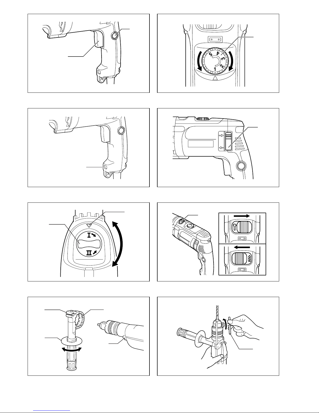
Voor Model HP2071, HP2071F (Fig. 9)
Houd de ring vast en draai de bus naar links om de klau-
wen van de boorkop te openen. Steek de boor zo ver
mogelijk in de boorkop. Houd de ring weer stevig vast en
draai de bus naar rechts om de boorkop vast te zetten.
Om de boor te verwijderen, houdt u de ring vast en draait
u de bus naar links.
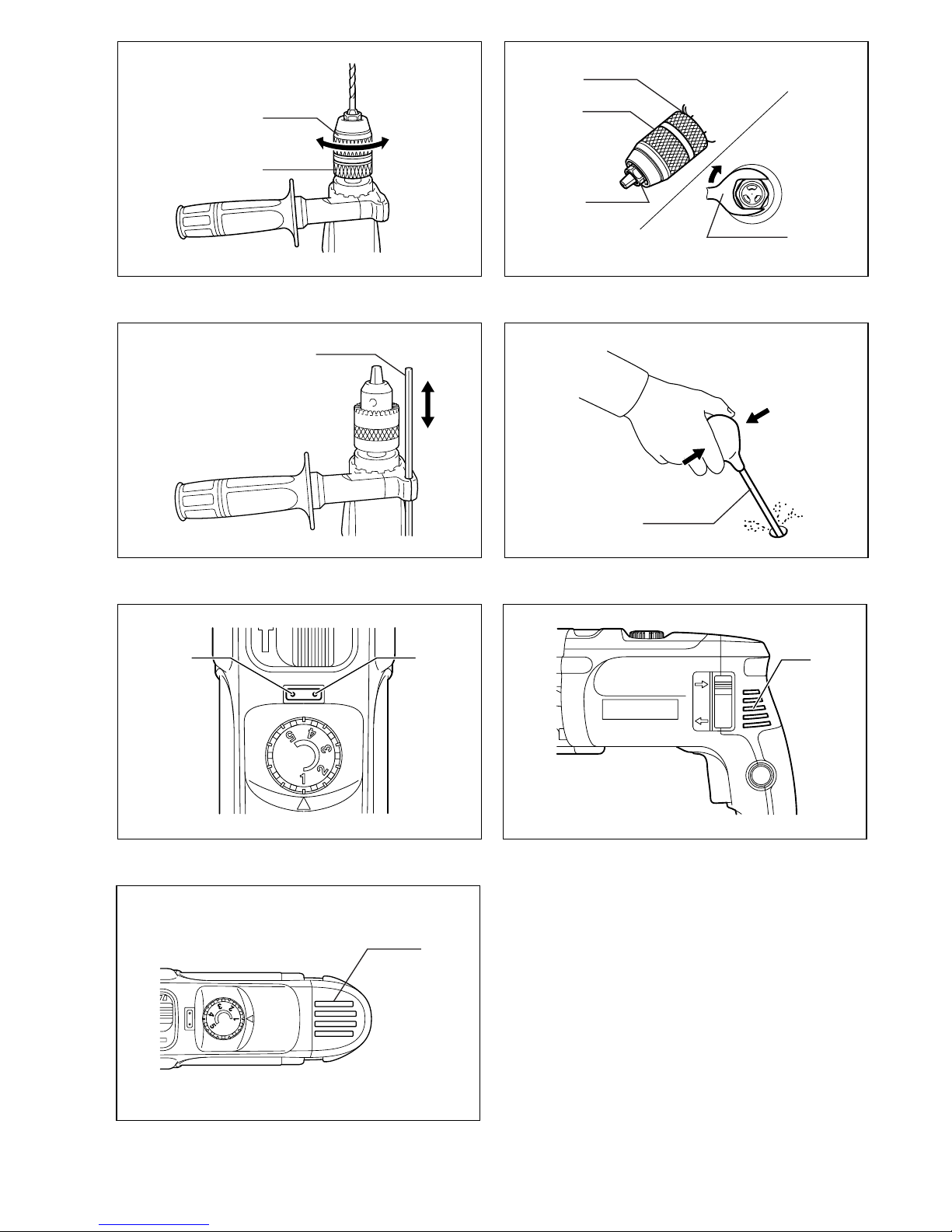
OPMERKING:
• Als de sleutelloze boorkop niet kan worden losgedraaid
omdat een boor in de klauwen van de boorkop vastge-
klemd zit, kunt u de boorkop als volgt losmaken.
1. Houd de bus stevig op haar plaats met een water-
pomptang of iets dergelijks. (Let op: Zet de tang niet
op de borgring.)
2. Zet de sleutel 19, een verstelbare sleutel of een
andere geschikte sleutel op de zeskante moer aan
de voorkant van de boorkop. Draai de sleutel
rechtsom om de boorkop los te draaien, zoals afge-
beeld in Fig. 10.
Dieptemaat (Fig. 11)
De dieptemaat is nuttig voor het boren van gaten van
gelijke diepte. Maak de zijhandgreep los en steek de
dieptemaat in het gat in de zijhandgreep. Stel de diepte-
maat in op de gewenste diepte en zet de zijhandgreep
vast.
OPMERKING:
• De dieptemaat kan niet worden gebruikt in de positie
waarbij deze tegen het lichaam van het gereedschap
zit.
BEDIENING
Hamerend boren
LET OP:
• Op het moment dat de boor door het gat heen dringt, of
wanneer het boorgat verstopt raakt met spanen en
metaaldeeltjes, of wanneer het gereedschap op ver-
sterkingsstaven in gewapend beton stoot, wordt er plot-
seling een enorme wringingskracht op het
gereedschap/boor uitgeoefend. Gebruik daarom altijd
de zijhandgreep (hulphandgreep) en houd het gereed-
schap tijdens het gebruik stevig vast bij zowel de zij-
handgreep als de hoofdhandgreep. Als u dit niet doet,
kunt u de controle over het gereedschap verliezen en
mogelijk zware verwondingen oplopen.
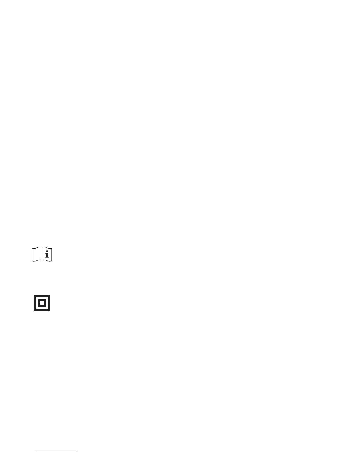
Wanneer u in beton, graniet, tegels e.d. gaat boren, dient
u de werking-keuzeknop in te stellen op de gpositie om
de “boren plus hameren” werking te kiezen.
Gebruik altijd een boor met een wolfraamcarbide boor-
punt.
Plaats de boorpunt op de plaats waar u wilt boren en
druk de trekschakelaar in. Forceer het gereedschap niet.
Een lichte druk geeft de beste resultaten. Houd het
gereedschap stevig vast en zorg dat de boor niet uit het
gat wegslipt.
Oefen geen grotere druk uit wanneer het boorgat ver-
stopt raakt met spanen of schilfertjes. Laat in plaats daar-
van het gereedschap onbelast draaien en verwijder de
boor gedeeltelijk uit het boorgat. Wanneer u dit een paar
keer herhaalt, zal het boorgat schoon worden en kunt u
normaal verder boren.
Blaasbalgje (los verkrijgbaar accessoire) (Fig. 12)
Gebruik het blaasbalgje nadat het gat is geboord, om stof
uit het gat weg te blazen.
Boren
Wanneer u in hout, metaal of plastic materialen gaat
boren, dient u de werking-keuzeknop in te stellen op de
mpositie om de “alleen boren” werking te kiezen.
Boren in hout
Bij boren in hout krijgt u de beste resultaten met houtbo-
ren die voorzien zijn van een geleideschroef. Het boren
wordt dan vergemakkelijkt aangezien de geleideschroef
de boor in het hout trekt.
Boren in metaal
Om te voorkomen dat de boor slipt wanneer u een gat
begint te boren, moet u met een drevel en een hamer
vooraf een deukje slaan op de plaats waar u wilt boren.
Plaats vervolgens de boorpunt in het deukje en begin te
boren.
Gebruik altijd boorolie wanneer u in metaal boort. De
enige uitzonderingen zijn ijzer en koper die droog
geboord dienen te worden.
LET OP:
• Door overmatige druk op het gereedschap uit te oefe-
nen verloopt het boren niet sneller. Integendeel, bij
overmatige druk op het gereedschap zal de boorpunt
beschadigd raken, zullen de prestaties van het gereed-
schap verslechteren, en zal het gereedschap minder
lang meegaan.
• Op het moment dat de boor door het gat heen dringt,
worden enorme spanningen uitgeoefend op het
gereedschap/boor. Houd daarom het gereedschap ste-
vig vast en wees op uw hoede wanneer de boor door
het werkstuk heen begint te dringen.
• Wanneer de boor klemraakt, keert u met de omkeer-
schakelaar gewoon de draairichting om, om de boor uit
het gat te krijgen. Houd het gereedschap echter goed
vast, omdat het anders plotseling uit het gat weg kan
schieten.
• Zet kleine werkstukken altijd goed vast in een span-
schroef of iets dergelijks.
Wanneer u in hout, metaal of plastic materialen gaat
boren, dient u de werking-keuzeknop in te stellen op de
mpositie om de “alleen boren” werking te kiezen.
ONDERHOUD
LET OP:
• Zorg altijd dat het gereedschap is uitgeschakeld en de
stekker uit het stopcontact is verwijderd alvorens inspec-
tie of onderhoud aan het gereedschap uit te voeren.
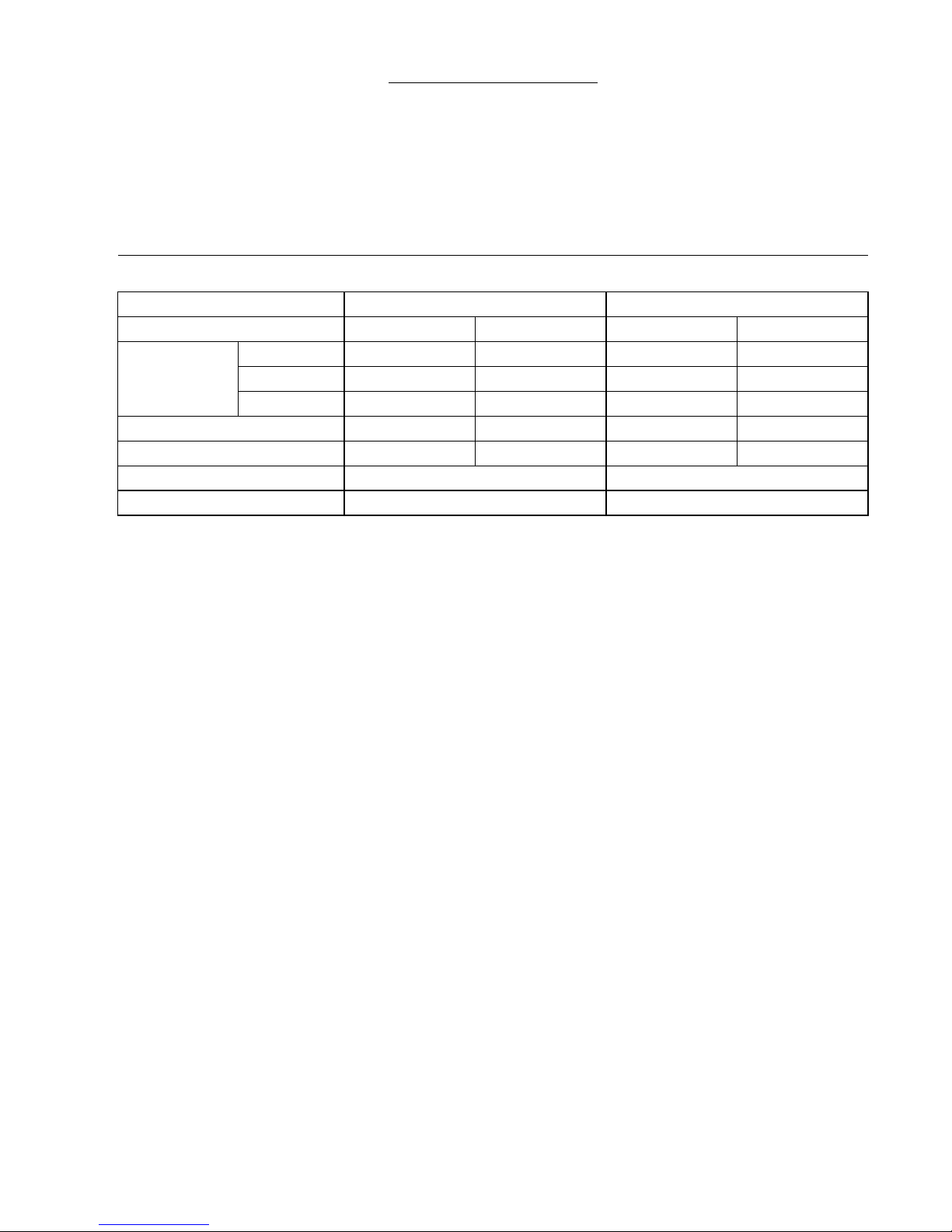
Indicatielampjes (Fig. 13)
Het groene spanning-AAN indicatielampje brandt wan-
neer het gereedschap is ingeschakeld. Als het indicatie-
lampje brandt maar het gereedschap niet start, zijn de
koolborstels mogelijk versleten, of is er een defect in het
elektrische circuit of de motor. Als het indicatielampje niet
brandt en het gereedschap niet start, is er mogelijk een
defect in de AAN/UIT trekschakelaar of de stroomkabel.
Het rode overbelasting-indicatielampje brandt wanneer
het gereedschap overbelast wordt. In zo’n geval zal het
voortgezet gebruik van het gereedschap resulteren in
storing of defect van het gereedschap.
Laat het gereedschap onbelast draaien om het te laten
afkoelen.

23
Schoonmaken van de ventilatiegaten
(Fig. 14 en 15)
Houd het gereedschap en zijn ventilatiegaten altijd
schoon. Reinig regelmatig de ventilatiegaten om te voor-
komen dat deze verstopt raken.
Om de VEILIGHEID en BETROUWBAARHEID van het
gereedschap te handhaven, dienen alle reparaties,
inspectie en vervanging van de koolborstels, en alle
andere onderhoudswerkzaamheden of afstellingen te
worden uitgevoerd bij een erkend Makita servicecentrum
of fabriekscentrum, en altijd met gebruik van originele
Makita vervangingsonderdelen.
ACCESSOIRES
LET OP:
• Deze accessoires of hulpstukken worden aanbevolen
voor gebruik met het Makita gereedschap dat in deze
gebruiksaanwijzing wordt beschreven. Het gebruik van
andere accessoires of hulpstukken kan gevaar voor
persoonlijke verwonding opleveren. Gebruik de acces-
soires of hulpstukken uitsluitend voor het gespecifi-
ceerde doel.
Wenst u meer informatie over deze accessoires, neem
dan contact op met het dichtstbijzijnde Makita service-
centrum.
• Boor met wolfraamcarbide boorpunt
• Gatzagen
• Blaasbalgje
• Veiligheidsbril
• Sleutelloze boorkop 13
• Boorkop
• Handgreepmontage
• Dieptemaat
• Plastic draagkoffer
Other manuals for HP2070
13
This manual suits for next models
3
Table of contents
Languages:
Other Makita Drill manuals

Makita
Makita XPH07 User manual

Makita
Makita DF333D User manual

Makita
Makita HP1631 User manual

Makita
Makita DDF484 User manual

Makita
Makita HP347D User manual

Makita
Makita 8271D User manual

Makita
Makita HR3541FC Manual

Makita
Makita 8406 User manual

Makita
Makita DF012D User manual

Makita
Makita 8271D User manual

Makita
Makita 6390D User manual

Makita
Makita M6200 User manual

Makita
Makita DDF446 User manual

Makita
Makita 8419B-2 User manual

Makita
Makita DHP448 User manual

Makita
Makita BDF343 User manual

Makita
Makita DHR263 User manual

Makita
Makita DDF484RF1J User manual

Makita
Makita BDA340 User manual

Makita
Makita df330d User manual