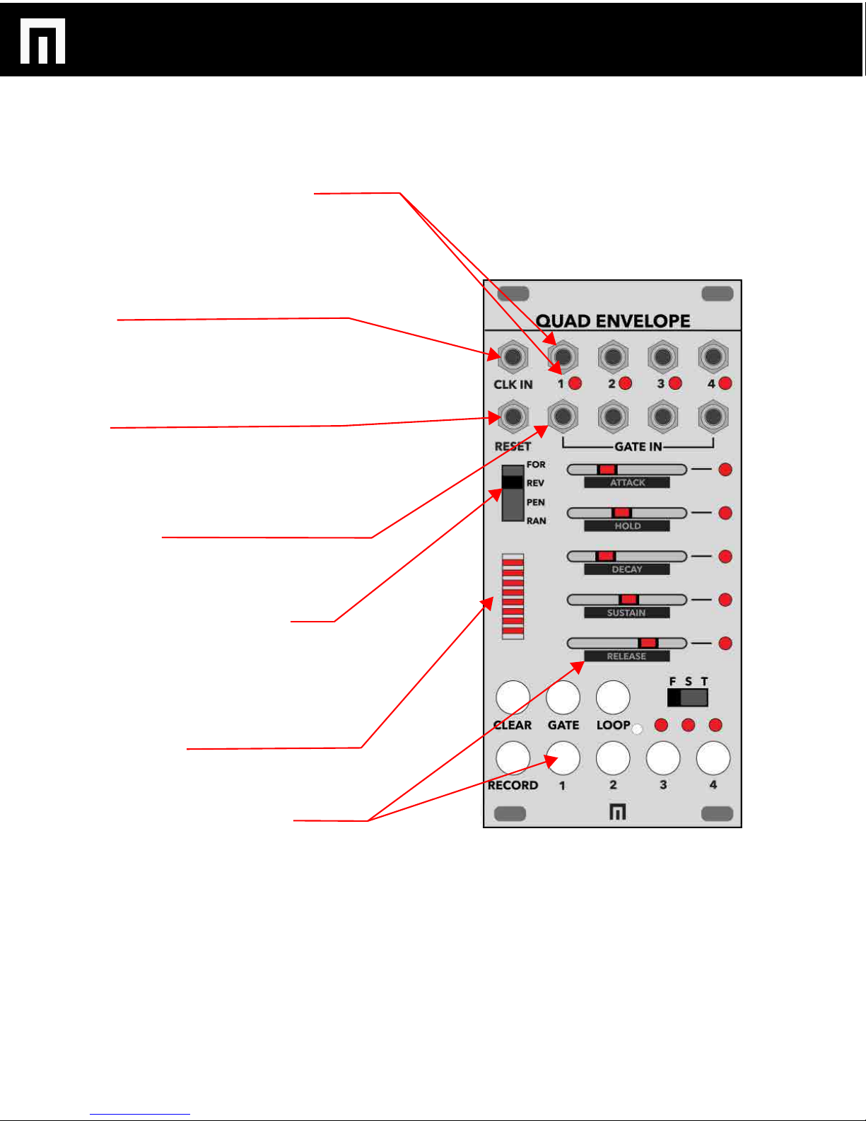
ENVELOPE 1-4 CHANNEL SELECT BUTTONS:
To select an envelope for parameter editing, press one of
these buttons. The active envelope LED will now be lit and you
can now start dialing various settings. To switch to another
envelope, push another one of the buttons and so forth.
RECORD:
To record parameter automation in a sequence for an
envelope, select the envelope channel button you want to
record sequenced automation so that it is lit, then hold the
RECORD button while you move the sliders. Make sure you
are already receiving incoming clock or this feature will not
work otherwise. Now you can change the direction of the
sequence as well by adjusting the sequence direction switch.
CLEAR:
To clear an automated sequenced recording for an envelope,
press the envelope channel select button so that it is lit, then
hold the CLEAR button while moving sliders.
FAST/SLOW/TEMPO SPEED SWITCH:
Set each envelope to either FAST, SLOW or TEMPO based.
See pg. 7 for more information and measurements for this
feature.
TRIGGER MODE:
TRIGGER MODE is the default mode (both GATE and LOOP
buttons are off). In this mode, an envelope will start when an
external input (gate or trigger), is patched and sending signal
to the envelope GATE inputs. It is simply looking for a rising
edge as the start point.
LOOP MODE:
To enter LOOP MODE, press an envelope channel select
button to enter editing mode and then press the LOOP
button. In this mode the envelope will loop back to attack as
soon as release reaches zero.
GATE MODE:
To enter GATE mode, press an envelope channel select button
to enter editing mode and then the GATE button. This mode
will play a standard AHDSR envelope when a trigger or gate
input is patched and said envelope will respond accordingly
to the pulsewidth of the incoming gate (shorter or longer
pulsewidths will affect the length of the HOLD setting).
GATE/LOOP MODE:
To enter GATE/LOOP mode, select an envelope
button to enter editing mode and then the GATE and the
LOOP button so that they are both lit.
In this mode, a loop will cycle within the pulsewidth of the
incoming gate. It will start looping at the rise of the gate and
stop looping when the gate pulsewidth ends at zero.
QUAD ENVELOPE MANUAL V.1
PG. 6
CONTROLS
LINK MODE:
Link Mode allows you to link envelope channels
2-4 to the same incoming trigger/gate input on
channel 1.
To link: Hold down channel button 1 while
selecting 2-4. You will now see that when you
press the channel 1 button, the buttons for the
other channels that are linked will also be lit.