Malekko VARIGATE 4+ User manual

VARIGATE 4+ MANUAL V.1
814 SE 14TH AVENUE
PORTLAND OR 97214
USA
www.malekkoheavyindustry.com

TABLE OF CONTENTS
VARIGATE 4+ MANUAL V.1
SPECIFICATIONS 1
INSTALLATION 2
DESCRIPTION 3
OVERVIEW 4-5
PROGRAMMING GATES PER STEP 6
PROGRAMMING CV/NOTES PER STEP 7
TRACK MODE 8
SAVING AND RECALLING PRESETS AND BANKS 9
RANDOMIZING 10
USING VARIGATE 4+ WITH VARIGATE 8+ AND VOLTAGE BLOCK 11
WARRANTY 12

SPECIFICATIONS
VARIGATE 4+ MANUAL V.1
FORMAT:
EURORACK
DIMENSIONS:
12HP, 26mm deep
INTERNAL AND EXTERNAL SIGNALS (3.5mm jacks):
0-5V Logic I/O
MAX CURRENT:
+12V: 90mA
-12V: 13mA
+5V: n/a
PG. 1

INSTALLATION
VARIGATE 4+ MANUAL V.1
RED STRIPE DOWN
Remove module from packaging.
Power down your modular synthesizer and disconnect the power cable from the
wall outlet.
Attach the included power cable to the module’s power connector and connect
the other end to the power distribution bus in your EuroRack synthesizer case.
Position the red stripe DOWN on your Varigate 4+.
Position the module on the mounting rails in your EuroRack case and screw
down mounting screws. Power up! If your case does not turn on properly then
you have installed the module incorrectly. Simply power down and make sure to
follow the diagram when reconnecting the module.
PG. 2

The Varigate 4+ is a 4-channel, 8-step sequencer that includes the features of the original Varigate 4, PLUS the
new option to output both CV (quantized or unquantized) and gates simultaneously. Other new features
include a Play/Stop function, Preset Banks (4×4), Glide Per Step, Scales and can also be configured as master
for the Malekko Voltage Block as well as a slave to the Varigate 8+ if you’re looking to expand your total
channels and presets (up to 14 channels and 100 presets with V8+).
Each Channel (or Track) correlates with it’s own sequencer (so 4 independent sequencers). The addition of the
Gate/CV Switch allows for switching between 4 channels of CV, 2/2 for 2 channels of CV and 2 channels of
gates, or all 4 channels to output only gates. Additionally, each step of a sequencer can be programmed with
Probability for gates, Repeats, Glide and Notes (when in a CV mode). There is a also a Randomization feature for
Repeats, Notes and Glide. Channel parameters for Scales, Sequence Direction (Forward, Reverse, Pendulum
and Random), Sequence Length, Division, Multiplication and Pulsewidth are all easily accessible using Track
Mode.
Easy Preset Recall makes the Varigate 4+ perfect for live performance. Pair it with the Malekko Voltage Block for
maximum control!
Features include:
-Switch between 4 channels of 5v gate outputs, 4 channels of CV outs or 2 gates and 2 CV outs
-8 steps per channel
-GLIDE per step
-PLAY/STOP function
-DIVIDE and MULTIPLY clock per channel
-Adjust sequence length per channel
-Adjust PULSEWIDTH per channel
-Program NOTES (for CV outs)
-Quantized SCALE adjustment
-TEMPO COURSE adjustment per bank of presets (This parameter adjusts the internal clock between 30 and
255 BPM
-TEMPO FINE adjustment (This parameter adjusts the clock +/- 25 BPM)
-Change SEQUENCE mode per channel (Forward, Reverse, Pendulum and Random)
-CLK IN: Clock input with LED indicator
-RESET: Gate input for resetting to step 1
-CLK OUT: Clock output with LED indicator
-PROBABILITY: Control the probability of a step outputting a gate.
-REPEAT: Control the amount of repeats per step
-RANDOMIZER functions for Repeat, Note, and Glide
-Saved PRESETS function
-Slave Voltage Block to Varigate 4+
-Slave Varigate 4+ to Varigate 8+ for use as an “expander” (for a total of 14 channels)
-LED BAR GRAPH: displays the step currently being adjusted as well as a final overview of all
adjusted steps.
-LEDs for A,B,C and D indicating gate outs, notes for each channel.
VARIGATE 4+ MANUAL V.1
DESCRIPTION
PG. 3

OVERVIEW
VARIGATE 4+ MANUAL V.1
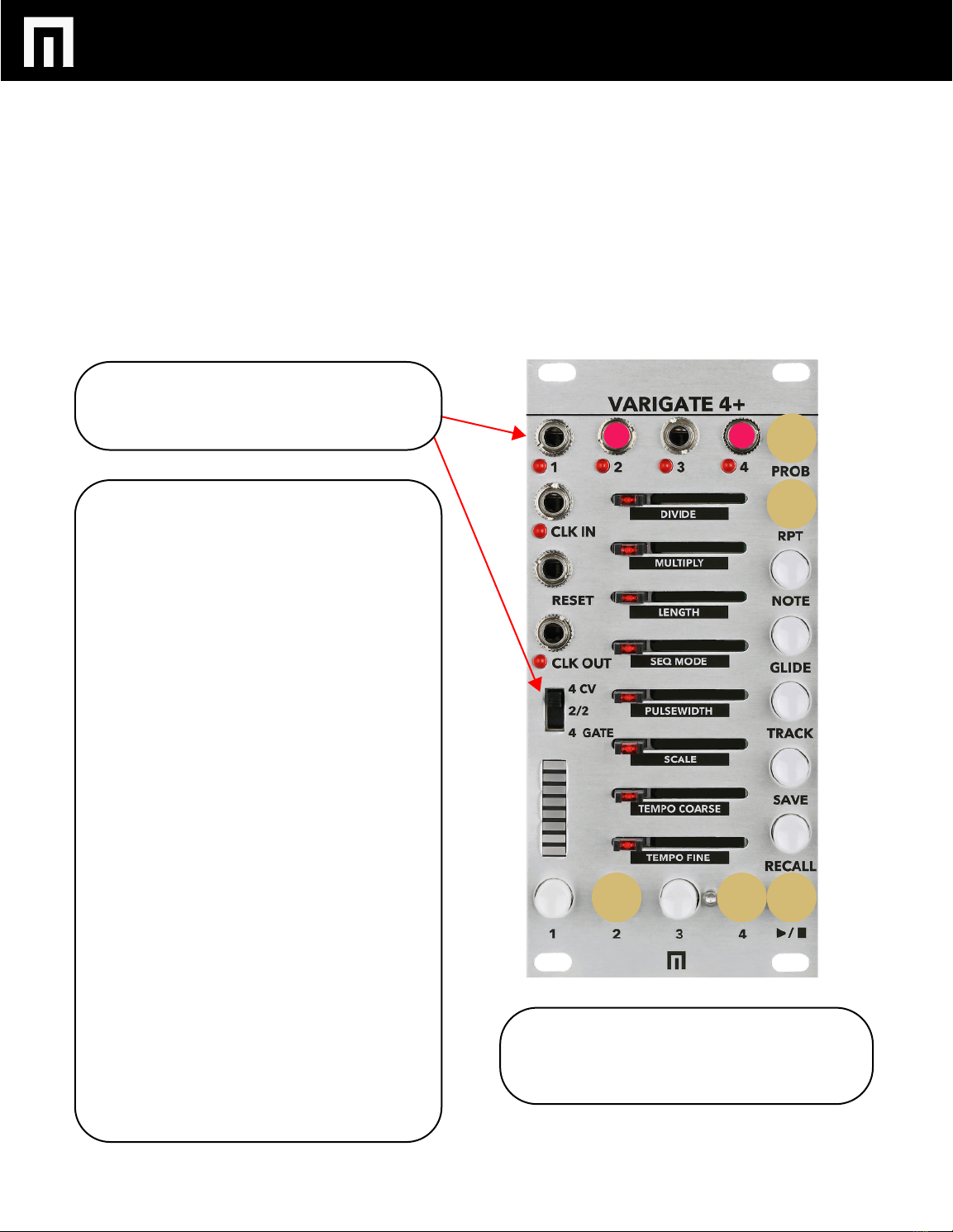
GATE and CV OUTPUT CHANNELS 1-4:
With LED indicators: Connect your patch cables
from these outputs to other module gate, trigger
or CV inputs depending on the mode you’re in
(see MODE switch for more info).
CLK IN:
External CLOCK INPUT with clock indictor.
RESET:
Gate input for resetting to step 1.
CLK OUT:
CLOCK OUTPUT with LED indicator.
MODE SWITCH:
4 CV MODE: Enables CV output on all 4 channels.
2/2 MODE: Enables CV output on Channels 1
and 3 and Gate outputs on channels 2 and 4.
4 GATE: All outputs are gate outputs.
STEP SLIDERS:
Move to adjust various per-step parameters
(PROBABILITY, REPEAT, NOTE, GLIDE per step) or
features listed underneath each slider when in
TRACK MODE (see TRACK for more info).
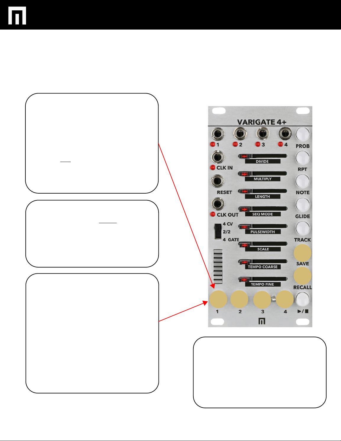
BUTTONS 1-4:
Press BUTTON 1 to access parameter adjust-
ments for CHANNEL 1 and so forth. NOTE: You
can also SAVE PRESETS to these buttons as well
as access BANKS of PRESETS. TO SAVE A
PRESET: Hold SAVE while pressing a button. TO
RECALL A PRESET: HOLD RECALL while pressing
a button. The PRESET that is active will pulse.
PG. 4
LED BAR GRAPH:
Displays various mode settings 1 through 8
(active steps, scales, sequence modes etc.).

VARIGATE 4+ MANUAL V.1
PG. 5
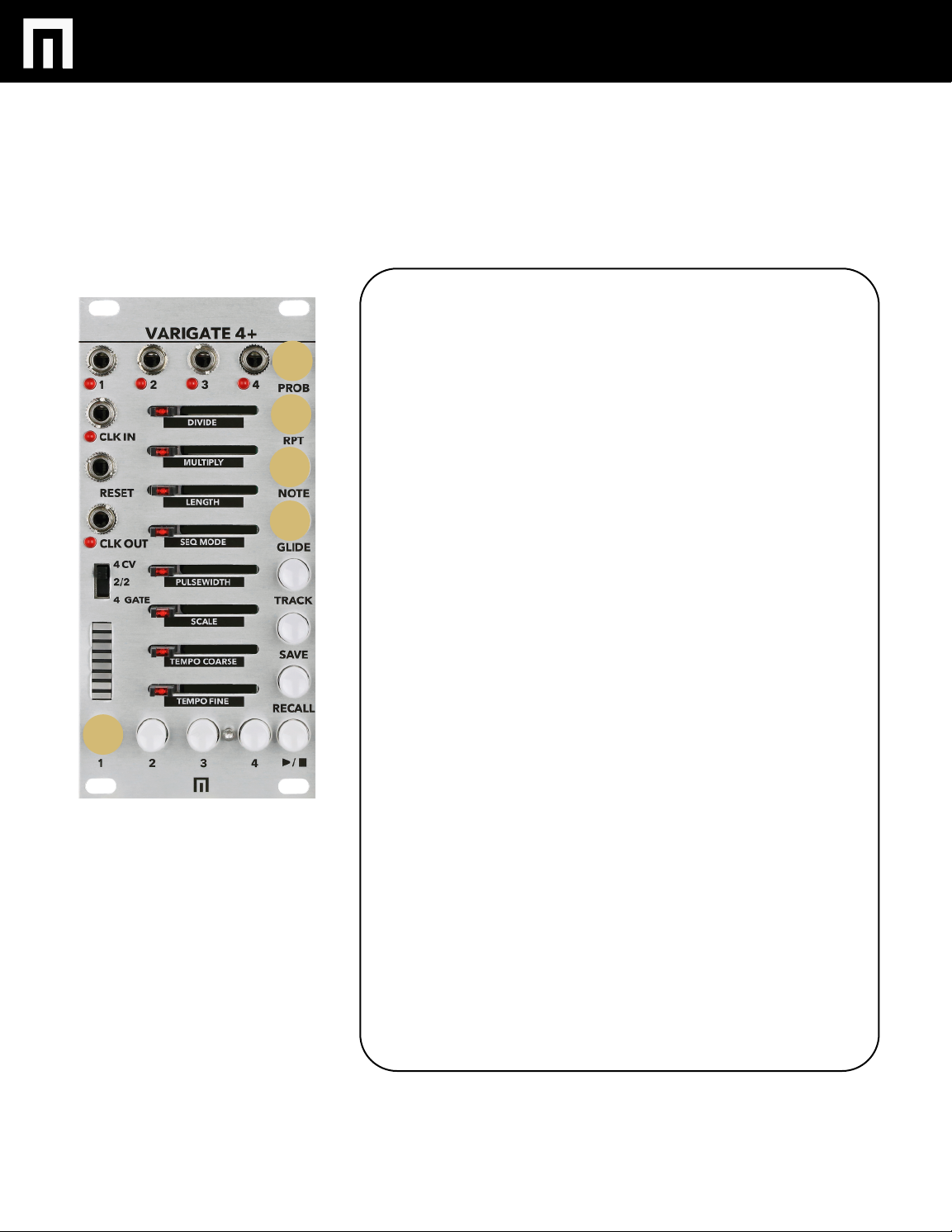
PROB:
Select and then adjust a step slider to control
the amount of probability per step. NOTE:
HOLDING PROB and then SELECTING RPT,
NOTE or GLIDE will engage the randomize
function for those features and for a selected
channel.
RPT:
Select and then adjust a step slider to control
the amount of repeats per step.
NOTE:
Select and then adjust a step slider to add
CV per step.
GLIDE:
Select and then adjust a step slider to add glide
per step.
TRACK:
Select to enter TRACK MODE for adjusting all
of the features listed in black underneath the
sliders (DIVIDE, MULTIPLY, SEQUENCE
LENGTH, SEQUENCE MODE, PULSEWIDTH,
SCALE, TEMPO COARSE AND TEMPO FINE
per channel).
SAVE:
Hold and then select Buttons 1-4 to save your
current settings to a preset.
RECALL:
Hold while selecting a saved preset to RECALL
saved presets.
HOLDING SAVE + RECALL and then selecting
buttons 1-4 will change BANKS.
PLAY / STOP: Press to start or stop the
Varigate 4+
VARIGATE 4+ MANUAL V.1
PROGRAMMING GATES PER STEP
ADJUST GATE/CV SWITCH to 2/2 to enable
CV output on Channels 1 and 3 and Gate
outputs on channels 2 and 4.
GATE PROGRAMMING:
PRESS THE PLAY BUTTON so the sequence is
playing. By default the sequence will play
forward (and the LED’s on the sliders will cycle
top to bottom for each of the 8 steps).
Select CHANNEL button #2 (button will be
illuminated).
The PROBABILITY button will be illuminated
indicating you’re ready to start programming
gates per step. Now adjust a slider to the right
to add a gate for a given step (you will also see
each active step light up on the LEDs under-
neath each channel jack). If you move a step
slider all the way to the right, the chance that
that gate will occur is 100%. Setting the slider to
the center and the gate will occur 50% of the
time and so forth.
If you want to change TEMPO, simply select the
TRACK button, then adjust the sliders for
TEMPO.
Now add some REPEATS on a step by pressing
the REPEAT button. Move one of the active
steps to the right to add multiple gates to that
step (great for adding hi-hat rolls for instance).
You can dial exact repeats per step (refer the
LED bargraph for 1-8 repeats per step).
Now repeat the above for CHANNEL #4.
If you want to just program GATES, switch to 4
GATE outs.
PG. 6
COPY/PASTE: To copy and paste newly
programmed step sequence data to another
channel, simply hold down one of the CHANNEL
buttons while selecting another channel button.

PROGRAMMING CV/NOTES PER STEP
VARIGATE 4+ MANUAL V.1
CV/NOTE PROGRAMMING:
Select CHANNEL button #1.
The NOTE button will be illuminated indicating
you’re ready to start programming unquantized or
quantized CV per step. Unquantized CV is useful for
animating other modules and quantized for notes
within a scale (patched to a module with a 1v/oct or
“pitch” input for instance). All CV that is
programmed within a sequence will be set to
unquantized by default and until you set the SCALE
for that channel.
Adjust sliders to the right to program CV per each
step. You can program up 5 volts per step. The LED
bar graph indicates relative value of CV per step.
One fully lit bar is approximately 1/8 of the 5V CV
range of that channel. A fully lit (slider all the way
right) bargraph represents the full 5V range of that
channel, an empty bargraph indicates 0V.
To quantize CV you’ve just programmed, select
TRACK and then move the slider for SCALE. You’ll
notice that the LED bargraph now indicates different
scale settings. See pg. 8 for the available scales. Now
each step will be quantized cv/notes within the scale
you’ve selected.
Once you have CV programmed, you can add
GLIDE to a step (a smooth transition between each
step). Simply move sliders to the right to add GLIDE
per step.
Now repeat the above for CHANNEL #3.
If you want to just program CV on all 4 channels,
switch to 4 CV outs.
OCTAVE RESTRICT MODE: Once quantized CV is
programmed on a step, you can fine tune it by using
OCTAVE RESTRICT MODE (you must already be in
quantized mode first). Now hold the NOTE button
while moving the slider to program that note within
the current octave (there are 5 octaves available).
PG. 7

VARIGATE 4+ MANUAL V.1
TRACK MODE
PG.8
DIVIDE:
To DIVIDE a sequence for a given channel, move
the DIVIDE slider to the right. The position of the
slider affects the amount of division down to 1/8
(refer to LED bargraph while programming).
MULTIPLY:
To MULTIPLY a sequence for a given channel, move
the MULTIPLY slider to the right. The position of the
slider affects the amount of multiplication up to 8x.
LENGTH:
To change the length of a sequence for a given
channel, move this slider to the right. Sequence
length goes up to 8 steps per sequence or down to
1 (the LED bar graph indicates length).
SEQUENCE MODE:
To change the direction of a sequence for a given
channel, move this slider to the right. The LED bar
graph indicates the 4 available sequence
directions: FORWARD, REVERSE, PENDULUM or
RANDOM in this order. Bar 1 on the bar graph is
FORWARD and so forth.
PULSEWIDTH:
Move this slider to the right to increase the width of
all gate pulses in a sequence. To decrease the width
of all pulses, move the slider to the left.
SCALE:
To change the SCALE of a particular sequence of
CV/NOTES specifically, move the slider to the right.
You’ll see the LED bargraph indicating the different
available scales. From top to bottom on the LED
bargraph: Unquantized, Major Pentatonic, Minor
Pentatonic, Blues, Dorian, Minor, Major,
Chromatic
TRACK:
DIVIDE, MULTIPLY, SEQUENCE LENGTH, SEQUENCE MODE, PULSEWIDTH, SCALE, TEMPO COARSE AND TEMPO FINE can
be adjusted per CHANNELS 1-4. To enter TRACK MODE, simply select TRACK and the CHANNEL button you want to edit.
TEMPO COARSE AND FINE: To change the tempo
move this slider to the right. Coarse adjusts the
internal clock between 30 and 255 BPM. TEMPO
FINE adjusts the clock +/- 25 BPM. You can save
different tempos to different banks of presets.
Note that TEMPO adjustment is only available while
in internal clock mode.
VARIGATE 4+ MANUAL V.1
SAVING & RECALLING PRESETS AND BANKS
The CHANNEL buttons also act as PRESET slots as
well as BANK slots. There are a total of 4 preset
slots per bank and 4 banks for a total of 16 preset
slots.
During playback, you will see the active preset
pulsing with tempo.
TO SAVE A PRESET:
Press and hold the SAVE button while you select
one of the CHANNEL buttons to save all sequence
settings programmed on channels 1-4 to one
preset (this includes TRACK mode settings per
channel as well).
BANKS:
Your first set of saved presets are saved to BANK
1 by default. On power up, BANK 1 will be active
by default as well.
To recall/save presets to BANK 2:
Hold the SAVE + RECALL button for about 1
second until both buttons are illuminated at the
same time. Now press BUTTON #2 to enter BANK
#2, BANK #3 and so forth. Now you can save the
active settings/preset to the available preset slots
in this new bank. Follow the same steps to recall
each available bank of presets.
NOTE: MAKE SURE THAT YOU SAVE ANY EXIST-
ING PRESETS BEFORE SWITCHING TO A NEW
BANK OR YOUR CHANGES WILL BE LOST.
CLEARING PRESETS and CHANNELS:
You can clear a preset by holding the TRACK
button until it is pulsing, then press each CHANNEL
button 1-4 you wish to clear. You can then save that
cleared preset or just start programming new
parameter changes etc.
To overwrite an existing/active preset, simply start
programming changes to parameters and save
again.
PG.9
TO RECALL A PRESET:
Once you’ve saved a few different presets, you
can now recall them by holding the RECALL
button while selecting a saved PRESET. The active
preset will pulse. Also note that the recalled
PRESET will play back once the active preset and
all sequences in this preset have completed their
cycles (this includes sequences that have been
divided).
RANDOMIZING
You can randomize the following features on each step for a given
CHANNEL.
REPEAT
NOTE
GLIDE
Once in RANDOMIZE MODE for these features, sliders positioned full
right equals full randomization for a given step. Sliders positioned to
full left equals zero randomization.
RANDOMIZE REPEATS PER STEP:
Hold PROBABILTY + REPEAT for a second until REPEAT is pulsing. Now
move step sliders to the right to program random repeats per step. If
you move a step slider to the right to 4 for instance (refer the LED bar
graph), the range will be set from 1 to 4 repeats for that step and will
randomize within this range on every cycle of the sequence. You can
also add randomization to already programmed repeats per step and
within a set range. If you already have 3 repeats programmed on a step
and you hold PROBABILITY + NOTE, then move that step slider to the
right to 5 for instance, your randomized repeat range will now be
between 3 and 5 for that step every time the sequence cycles.
RANDOMIZE CV/NOTES PER STEP:
Hold PROBABILITY + NOTE for a second until NOTE is pulsing. Now
move sliders to the right to start adding random cv/notes per step. If
you move a step slider to 4 for instance, the range will be set from 1 to
4 and will randomize within this range on every cycle of the sequence.
You can also add randomization to already programmed cv/notes per
step and within a set range. Hold PROBABILITY + NOTE and move one
these step sliders to 7 for instance. Now the range of randomization will
occur between what was already programmed +7 for that step every
time the sequence cycles.
RANDOMIZE GLIDE PER STEP:
Hold PROBABILITY + GLIDE for a second until GLIDE is pulsing. If you
move the slider to the right to 4 for instance, the range for glide per
step will be set from 1 to 4 and will be randomized within this range on
every cycle of the sequence. You can also add randomization to existing
glide per step and within a set range. If existing glide is programmed
on a step and set at 3, and you then hold PROBABILITY + GLIDE, you
can then move that step slider to the right to 7 and the randomization
range will be set between 3 and 7 every time the sequence cycles.
PG. 10
VARIGATE 4+ MANUAL V.1

USING VARIGATE 4+ WITH VOLTAGE BLOCK
& VARIGATE 8+
VARIGATE 4+ MANUAL V.1
PG. 12
The Varigate 4+ utilizes busboard clocks.
The Varigate 4+ ships in MASTER MODE. This means anything else connected to the busboard that includes busboard clocking
will slave to the Varigate 4+ clock.
To slave Voltage Block to the Varigate 4+, you’ll need to set the Voltage Block to SLAVE MODE. Also make sure your Varigate 4+
jumpers are set to MASTER MODE. Slaving Voltage Block to Varigate 4+ allows you to save programmed parameters on your
Voltage Block within Varigate 4+ presets.
If you want to slave the Varigate 4+ to the Varigate 8+ to share clock, expand available channels and utilize all 100 Varigate 8+
presets, you will need to set your jumpers in reverse.
MASTER MODE
JUMPER SETTINGS
SLAVE MODE
JUMPER SETTINGS

WARRANTY
VARIGATE 4+ MANUAL V.1
PG. 13
This product is covered by the Malekko Heavy Industry warranty, for one year following the
date of purchase. This warranty covers any defect in the manufacturing of this product. This
warranty does not cover any damage or malfunction caused by incorrect use – such as, but
not limited to, power cables connected backwards, excessive voltage levels, or exposure to
extreme temperature or moisture levels. The warranty covers replacement or repair, as
decided by Malekko Heavy Industry. Please visit our website malekkoheavyindustry.com to
obtain full warranty information and to register your product for coverage.
Table of contents
Other Malekko Recording Equipment manuals


