MALEKKOHEAVYINDUSTRY.COM
VARIGATE 4 MANUAL V.1
PER-STEP PARAMETERS
The following parameters are set on a
per-step level: PROBABILITY, REPEAT,
and DELAY.
PROBABILITY - This parameter controls
the chance of a step being active.
EXAMPLE: (make sure you have connect-
ed a cable from Channel A to a sound
source like a drum module, “trigger input”).
Select button for Channel A, then select
button PROBABILITY, then adjust the
fader for Step 1. You will now notice that
Step 1 rate of probability that the gate will
trigger has increased according the
amount that the fader is moved either left
or right. Now move the faders for Step
2-8.
Repeat the above example for Channel B,
C, and D with other modules/trigger inputs.
If you want the probability behavior to act
like a standard gate sequencer (always
sending a gate on step), simply move the
fader for the corresponding step all the
way to the left or to the right.
.
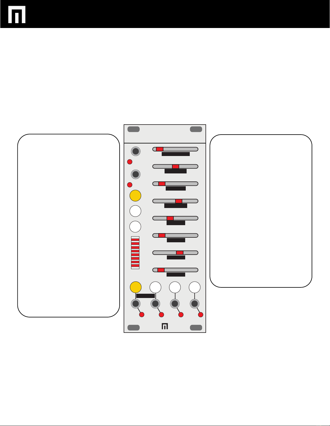
TEMPO COARSE
TEMPO FINE
CLK DIVIDE
PULSEWIDTH
A LENGTH
B LENGTH
C LENGTH
D LENGTH
A B C D
PROB
REPEAT
DELAY
VARIGATE 4
CLK IN
RESET
GLOBAL
REPEAT - This parameter controls the
amount of pulses per step. This can be
adjusted from 1-8 pulses.
EXAMPLE: Follow the same instructions-
for PROBABILITY, but select REPEAT
instead.
DELAY - This parameter introduces delay
on the selected step much like adding
shuffle. It will always fall within the step
being adjusted. The delay amount is
based on the clock rate so tempo
changes will not alter the pattern.
EXAMPLE: Follow the same instructions-
for PROBABILITY, or REPEAT but select
the DELAY instead.
To erase any of the above settings, simply
hold the buttons for PROB, REPEAT and
DELAY for 1 second.