Malta Dynamics R0007 Operator's manual

Visit www.MaltaDynamics.com for the latest user
instruction manual based upon date of manufacture.
FALL PROTECTION AND SAFETY EQUIPMENT
Malta Dynamics Conned
Space Rescue Tripod
User Instruction Manual
This instruction manual applies to the following models:
R0006

MegaPod User Instruction Manual
MaltaDynamics.com | 800-494-1840 2
Please read and understand the manufacturer’s instructions for each component
or part of the complete system. Manufacturer’s instructions must be followed for
proper use, care, and maintenance of this product. These instructions must be
retained and be kept available for the worker’s reference at all times. Alterations
or misuse of this product, or failure to follow instructions, may result in serious
injury or death.
NOTE: The user is advised to keep the user instructions documents for the life of
the product.
This manual must be read and understood in its entirety and used as part of
fall protection training program as required by OSHA or any stateregularity
agency. These instructions are intended to meet the manufacturer instructions
as required by ANSI Z 359.4-2013 The user mustfully understand the proper
equipment use and limitations.
1. GENERAL REQUIREMENTS, WARNINGS AND LIMITATIONS:
• The Equipment is designed for use as a part of a personal fall protection
system. Components must not be used for any other operation other than that
which it has been designed and approved. Fall Arrest system are designed
to comply with OSHA. Fall Restraint System must be designed by a Qualied
Person, and must be installed and used under the supervision of a competent
person.
• All authorized persons/users must refer the regulations governing occupational
safety, as well as applicable ANSI or CSA standards. Please refer to product
labeling for information on specic OSHA regulations, and ANSI and CSA
standards met by product.
• Consult a doctor if there is any reason to doubt a user’s ability to withstand
and safely absorb fall arrest forces. Age, tness, health conditions can seriously
affect the worker a fall occur. Pregnant Women and minors should not use this
equipment.
• Proper precautions should always be taken to remove any obstructions, debris,
material, or other recognized hazards from the work area that could cause
injuries or interfere with the operation of the system. All equipment must be
inspected before each use according to the manufacturer’s instructions. All
equipment should be inspected by a qualied person on a regular basis.
• To minimize the potential for accidental disengagement, a competent person
must ensure system compatibility.
• Equipment must not be altered in any way. Repairs must be performed
only by the Manufacturer, or persons or entities authorized in writing by the
manufacturer.

3MegaPod User Instruction Manual
MaltaDynamics.com | 800-494-1840
Visit www.MaltaDynamics.com for the latest user
instruction manual based upon date of manufacture.
• Any product exhibiting deformities, unusual wear, or deterioration must be
immediately discarded. Any equipment subject to a fall must be removed from
service. The authorized person/user shall have a rescue plan and the means at
hand to implement it when using this equipment.
• Never use fall protection equipment for purposes other than those for which
it was designed. Fall protection equipment should never be used for towing or
hoisting.
• All synthetic material must be protected from slag, hot sparks, open flames, or
other heat sources. The use of heat resistant materials is recommended in these
applications.
• Never use natural materials (manila, cotton,etc.) as part of a fall protection
system.
• Do not expose this equipment to chemicals which may have a harmful effect on
the materials used to construct it. Be especially aware of caustic environment,
or those that contain high levels of organic acids or bases. If you are uncertain
about the safe operation of this equipment in any environment, contact Malta
Dynamics for further instructions.
• Do not use the equipment near sharp edges, abrasive surfaces and looping
around small diameter structural members.
• Do not use the equipment around moving machinery or electrical hazards.
Malta Dynamics Tripod should be used only with the combinations of
components, sub-systems or both which may affect or interfere with the safe
function of one another. Be certain that connecting devices are compatible
and that other elements of the personal fall arrest systems are safe to use and
compatible before use.

MegaPod User Instruction Manual
MaltaDynamics.com | 800-494-1840 4
Brackets used with megapod variants-
Megapod
Dead Weight
Retrieval
block
Retrieval Mounting
bracket(SA17(26)
Product Over View
Shoes
Mini Hook(MH01
Locking
pin
Eye bolt
Pulley
Aluminum
cast head
Telescopic
legs
Direction of
Load Application
No No
YesY es
Supplied with Megapod
Can be purchased separately
Yes
Ref. No.
Part of
standard Part of
standard
Winch
Product
sY
Tripod
R0006 R0007 R0006 Bracket
Tripod
Tripod

5MegaPod User Instruction Manual
MaltaDynamics.com | 800-494-1840
Visit www.MaltaDynamics.com for the latest user
instruction manual based upon date of manufacture.
2. SYSTEM LIMITATIONS & REQUIREMENTS:
Consider the following limitations/requirements prior to installing or using this
equipment:
• Capacity: Malta Dynamics Tripod is designed for use by ONE person with a
combined weight (clothing, tools, etc.) of no more than 310 lbs. (140 kg) Make
sure all of the components in your system are rated to a capacity appropriate to
your application. Malta Dynamics Tripod is rated 5000lbs.
• Free Fall: Personal fall arrest systems used with this equipment must be set up
to limit the free fall to 6 feet (1.8 M) per ANSI Z359.1. Restraint systems must
be set up so that no vertical free fall is possible. Work positioning systems must
be set up so that free fall is limited to 2 feet (.6 m) or less. Personnel riding
systems must be rigged so that no vertical free fall is possible. Climbing systems
must be rigged so that free fall is limited to 18 inch. (.46 cm) or less. Rescue
systems must be rigged so that no vertical free fall is possible. See subsystem
manufacturer’s instructions for more information. Below gure illustrates fall
clearance requirements. There must be sufcient clearance below the user
to allow the system to arrest a fall before the user strikes the ground or other
obstruction. Clearance required is dependent on the following factors:
• Elevation of Anchorage
• Connecting Subsystem Length
• Deceleration Distance
• Free Fall Distance
• Worker Height
Movement of Harness Attachment Element
• Swing Falls: Swing falls occur when the anchorage point is not directly
above the point where a fall occurs. The force of striking an object in a
swing fall may cause serious injury or death. Minimize swing falls by
working as close to the anchorage point as possible. Do not permit a swing fall
if injury could occur. Swing falls will signicantly increase the clearance required
when a self-retracting lifeline or other variable length connecting subsystem is
used.
• Environmental Hazards: Use of this equipment in areas with environmental
hazards may require additional precautions to prevent injury to the user or
damage to the equipment. Hazards may include, but
are not limited to; heat, chemicals, corrosive environments, high voltage power
lines, gases, moving machinery, and sharp edges.
D
F
E
C
B
A
A
B
C
D
E
F
Connecting Subsystem (Energy
Absorbing Lanyard Shown)
Working Level
Lower Level or Obstruction
Free Fall -6ft. (1.8m) Max. (per ANSI Z3559.1)
Total Fall Distance Free Fall (D) + Deceleration (E)
Deceleration Distance

MegaPod User Instruction Manual
MaltaDynamics.com | 800-494-1840 6
CONNECTOR COMPATIBILITY LIMITATIONS
Malta Dynamics’ equipment must be coupled only to compatible connectors that
are suitable to your application. Ensure all connections are compatible in size,
shape, and strength. Ensure all connectors are fully closed and locked. OSHA
29 CFR 1926.502 prohibits the use of snap hooks to engage objects unless the
following requirements are met:
• Snap hook must be a locking model.
• Snap hook must be explicitly designed for such a connection.
Use of a non-locking snap hook can result in rollout (a process by which a snap
hook or carabiner unintentionally disengages from another connector or the
object to which it is coupled (ANSI Z359.0-2007). Malta Dynamics connectors
(snap hooks and carabiners) are designed to be used only as specied in each
product’s user’s instructions.
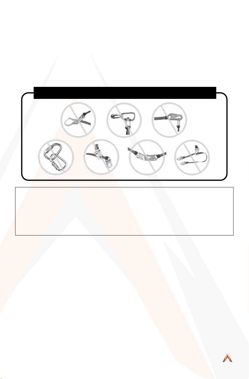
Avoid the following types of connections:
• Two or more snap hooks or carabiners attached to one D-Ring.
• A snap hook connected to its integral lanyard.
• A snap hook connected to a horizontal lifeline.
• Connection in a manner that results in a load on the gate. NOTE: Large
throat opening snap hooks should not be connected to standard size
D-Rings or similar objects, as such use will result in a load on the gate
if the hook or D-Ring twists or rotates. Large throat snap hooks are
designed for use on structural elements such as rebar or cross members
that are not shaped in such a way that they may capture the gate of the
hook.
• False engagement connections, where protruding features of the snap
hook or carabiner may catch on the anchor and seem fully engaged to
the anchor point. Always conrm engagement.
• Connection to snap hooks or carabiners.
• Direct connection to webbing lanyard, webbing loop, rope lanyard or
tie-back (unless the manufacturer’s instructions for both the lanyard
and connector specically allow such a connection).
• Malta Dynamics’ Full Body Harnesses shall be used as part of a
personal fall arrest system that limits the maximum free-fall distance to
six feet (1.8 m). If used with appropriate connecting systems, the Full
Body Harnesses may be used with free falls exceeding six feet (1.8m)
• Full Body Harnesses shall only be used as part of a work positioning
system that limits the maximum free-fall distance to two feet (0.6 m).
• Personal Energy Absorbers and Energy Absorbing Lanyards marked
with, “ANSI Z359.13,” and “Six-Foot Free Fall” are designed for up to
six feet. Free-fall applications have a maximum capacity of 310 pounds.
(141 kg) including clothing, tools, etc.
•

7MegaPod User Instruction Manual
MaltaDynamics.com | 800-494-1840
Visit www.MaltaDynamics.com for the latest user
instruction manual based upon date of manufacture.
• Not all fall protection components are rated for the same user weight
capacity. ONLY use components rated for the same weight capacity.
• This equipment is designed to be used in temperatures ranging from
-40ºF to +130ºF (-40°C to +54°C).
• Connection of a snap hook to a D-Ring, rebar, or other connection point
of improper dimensions in relation to the snap hook dimensions or
congurations that could cause the snap hook keeper to be depressed
by a turning motion of the snap hook, or such that snap hook or
carabiner will not fully close and lock, or that roll-out could occur.
• Illustration 3 depicts examples of inappropriate connections:
Illustration 3: Inappropriate Connections
NOTE: Other than 3,600 lb. (16 kN) gated hooks, large throat opening snap hooks
should not be connected to standard size D-rings or similar objects which will
result in a load on the gate if the hook or D-ring twists or rotates. Large throat
snap hooks are designed for use on xed structural elements such as rebar or
cross members that are not shaped in a way that can capture the gate of the
hook.
4. CONNECTING SUB-SYSTEMS:
Personal fall arrest systems used with this equipment must meet applicable
state, OSHA and ANSI requirements. A full body harness must be worn when
this equipment is used as a component of a personal fall arrest system. As
required by OSHA, the personal fall arrest system must be capable of arresting
the user’s fall with a maximum arresting force of 1,800 lbs. (8 kN), and limit the
free fall to 6 ft. (1.8 m) or less.
• Rescue Plan: Rescue operation must be performed by the trained and competent
personal. The rescue operation must be performed under the supervision of the
rescue expert team or personal. It is advised that while working on site work in
pairs. Before going for the work the user must have the rescue plan according to
the work.

MegaPod User Instruction Manual
MaltaDynamics.com | 800-494-1840 8
• If Equipment Is Subjected To A Fall: Remove the equipment from service
immediately if it has been subjected to the forces of a fall arrest. Contact your
distributor or Malta Dynamics about policies regarding replacement of Malta
Dynamics components involved in a fall.
5. SPECIFIC INSTRUCTIONS:
Malta Dynamics Anchors are designed to provide complete attachment system
to user in the event of a fall. These attachment systems must be connected to
the proper body support and connecting facility. These Anchors are meant to
hold the victim of fall till the rescue operation is performed, so this is important
that the whole system must have the all the essential components before going
for the use. The whole fall arrest system must be used by the trained/competent
person. It is advisable to make a checklist of the essential components according
to one’s use before going for work.
6. USE OF FALL ARREST SYSTEM:
The fall arrest system MUST ONLY be connected to the back attaching element
on the harness provided for the purpose (”D” ring or webbing attachment
extension) or to the chest anchorage points (“webbing link” or “D” link). The chest
anchorage points must imperatively be used together. The D-rings on the belt
and the ventral anchorage point must only be used for the attachment of a work
positioning or retaining system and never with a fall arrest system.
During use, check regularly the adjustment and/or attachment points.
7. ANCHORAGE STRENGTH: The anchorage strength required is dependent on
the application type. The following are the requirements of ANSI Z359.1 for these
application types:
• Fall Arrest: Anchorages selected for fall arrest systems shall have a strength
capable of sustaining static loads applied in the directions permitted by the
system of atleast- (1) 5,000 lbs.(23kN) for non-certied anchorages, or (2) Two
times the maximum arresting force for certied anchorages. When more than
one fall arrest system is attached to an anchorage, the strengths set forth in
(1) and (2) above shall be multiplied by the number of systems attached to the
anchorage.
As Per OSHA: Anchorages used for attachment of personal fall arrest systems
shall be independent of any anchorage being used to support or suspend
platforms and capable of supporting at least 5,000 lbs.(23kN) per user attached,
or be designed, installed and used as part of a complete personal fall arrest
systems which maintains a safety factor of at least two, and is under the
supervision of a qualied person.

9MegaPod User Instruction Manual
MaltaDynamics.com | 800-494-1840
Visit www.MaltaDynamics.com for the latest user
instruction manual based upon date of manufacture.
• Work Positioning: The structure to which the work positioning system is attached
must sustain static loads applied in the directions permitted by the work
positioning system of at least 3,000 lbs. (13.3 kN) or twice the potential impact
load, whichever is greater. See OSHA. When more than one work positioning
system is attached to an anchorage, the strengths stated above must be
multiplied by the number of work positioning systems attached to the anchorage.
• Restraint: Anchorages selected for restraint and travel restraint systems shall
have a strength capable of sustaining static loads applied in the directions
permitted by the system of at least: (1)1,000 lbs. (4.5 kN) for non-certied
anchorages, or (2)Two times the foreseeable force for certied anchorages.
When more than one restraint and travel restraint system is attached to an
anchorage, the strengths set forth in (1) and (2) above shall be multiplied by the
number of systems attached to the anchorage.
• Rescue: Anchorages selected for restraint and travel restraint systems shall have
a strength capable of sustaining static loads applied in the directions permitted
by the system of at least: (1) 3,000 lbs. (13.3 kN) for non-certied anchorages,
or (2) Five times the foreseeable force for certied anchorages. When more
than one restraint and travel restraint system is attached to an anchorage, the
strengths set forth in (1) and (2) above shall be multiplied by the number of
systems attached to the anchorage.
ANCHORAGE & ANCHORAGE STRENGTH: Anchorage and anchorage strength requirements are
dependent on the Full Body Harness. In accordance with ANSI Z3559.1, anchorages selected for fall
Arrest Systems must meet the anchorage strength requirements dened in below:
Anchorage Strength Requirements
Fall Arrest1
Restraint1
Work
Positioning1
Rescue1
Climbing
Certied Acnchorage2:
Non-Certied Acnchorage:
Certied Acnchorage2:
Non-Certied Acnchorage:
Certied Acnchorage2:
Non-Certied Acnchorage:
Certied Acnchorage2:
Non-Certied Acnchorage:
5,000 lbs. (23kN)
2 Times the Maximum Arresting Force for Certied Anchorage
1,000 lbs. (4.5kN)
2 Times the Foreseeable Force for Certied Anchorage
3,000 lbs. (13.3kN)
2 Times the Foreseeable Force for Certied Anchorage
3,000 lbs. (13.3kN)
5 Times the Foreseeable Force for Certied Anchorage
The structure which a climbing system is attached must sustain the loads required by that particular
system. See the instructions for the climbing system for requirements.
1 Multiple Systems: When more than one of the dened system is attached to an anchorage, the strength dened for Non- Certied
or certied anchorage shall be multiplied by the number of systems attached to the anchorage.
2 Certied Anchorage: An anchorage for fall arrest, positioning, restraint, or rescue systems that a qualied person certies to be
capable of supporting the potential fall force that meet the criteria for a certied anchorage prescribed in this standard.

MegaPod User Instruction Manual
MaltaDynamics.com | 800-494-1840 10
8. INSPECTION:
Before each use, proceed with a thorough visual examination to ensure
that the PPE is intact (the same applies to the equipment used with the
harness (connectors, lanyard) and take all necessary steps concerning the
implementation of rescue in total safety. In the event of your product gets
contaminated, consult the manufacturer or authorized agent. If you have any
doubts regarding the safe state of the product or if the product has been used to
arrest a fall, it is essential to immediately withdraw the PPE from use and send it
to the manufacturer or a qualied repair center for checking or destruction.
Following the inspection, the center will provide written authorization or refusal
for the use of the PPE. Never attempt to modify or repair PPE.
• Before each use of this equipment inspect it according to the following
guidelines: A formal inspection of fall protection products/components must be
performed at least every six months by a competent person other than the user.
The frequency of formal inspections should be based on conditions of use or
exposure. Record the inspection results in the inspection and maintenance log
at the end of this manual. The component should be checked for Cut, Frayed,
Heavily Soiled, welding burns etc. Metal parts like D-rings should be duly check
for the crack, bent, deformities, corrosions etc.
9. LIMITATIONS:
• Tripod should be a personal property of its user.
• It should not be used in highly acidic or basic environments.
10. FITTING & SIZING:
The Tripod comes in two variants i.e. 7ft.(2.10) and 10ft (3.05). Depending on the
condition of usage one can choose best option as per
requirement.
STEP 1: Place the Tripod on the floor with the feet on the
ground. Remove the locking Pins from the head and
the legs.
STEP 2: Fully spread the legs and then replace the locking pins
on head to secure the legs in the open positions.
STEP 3: Resecure the locking pins into legs, after adjustment
of the required height or in fully extended position.
STEP 4: Place the Tripod over the entry point. Adjust the
Tripod as necessary by removing pins in one leg
at a time. Adjust each leg so the Tripod sits level
above user’s entry point. Ensure that all pins are re-installed.
STEP 5: Place the Retrieval Block on the opposite leg of the Tripod, where the
winch is installed.
SA 17W(7ft.) & (10ft.)
SA 17 (7ft.) & (10ft.)
R0006
R0006

11 MegaPod User Instruction Manual
MaltaDynamics.com | 800-494-1840
Visit www.MaltaDynamics.com for the latest user
instruction manual based upon date of manufacture.
11. FALL CLEARANCE:
If there is a risk of fall or if the only anchorage is below the attachment points
on the harness, it is essential to use a lanyard provided with an energy absorber.
Before using a shock-absorbing lanyard, check that there is sufcient fall
clearance below the user to prevent any collision with the structure or the ground.
12. MATERIAL & CONSTRUCTION:
• Materials: High Strength Aluminium
• System Requirements:
• Compatibility of Components: Malta Dynamcis Fall Protection
equipment is designed to be used with Malta Dynamcis approved
components. Please contact Malta Dynamcis if you have a question
regarding compatibility. Making substitutions without approval from
Malta Dynamcis Fall Protection may lead to injuries and or death. A
Qualied person can make a determination on compatibility of
equipment from different manufacturers.
• Compatibility of Connectors:
Connectors (D-rings, hooks, carabiners) must be capable of supporting
at least 5,000 lbs. (23kN). Do not use equipment that is not compatible.
Non-compatible connectors may unintentionally disengage. Self-locking
snap hooks and carabiners are required by CSA, ANSI and OSHA. Connectors
must be compatible in size, shape, and strength.
• Making Connections: Only use self-locking
snap hooks and carabiners with any
Malta Dynamics Fall Protection equipment.
Do not use equipment that is not
compatible.

MegaPod User Instruction Manual
MaltaDynamics.com | 800-494-1840 12
Installation of retrieval block on megapod:
STEP 1 Locate the Tripod leg that has pre-installed mounting bracket for installing the
retrieval block.
STEP 2 Place the retrieval mounting bracket on the lower mounting bracket pre-installed
on the Tripod leg and insert the guiding pin into the slot. (refer g. 2 and 3)
STEP 3 Use solid pin for locking the Retrieval Mounting bracket on pre-installed mounting
bracket of Tripod leg. (refer g. 4)
STEP 4 Lock the solid pin on mounting brackets using cotter pin. (refer Fig. 4)
STEP 5 Insert retrieval block in bracket guided by aluminum guide provided on both side
of retrieval. (refer Fig. 5)
STEP 6 Lock the anchorage eye with bracket followed by solid pin and lock solid pin from
other end by inserting cotter pin. (refer g. 6&7). Now the retrieval block is ready to be
used on Tripod (refer g. 8)
13. OTHERS:
• Maintenance & Cleaning: Repairs to equipment can be made only by a Malta
Dynamics representative or person or entity authorized by Malta Dynamics.
Contact Malta Dynamics for maintenance and repair. Cleaning after use is
important for maintaining the safety and life of the equipment. Cleanse the
equipment of all dirt, corrosives, and contaminants. If the equipment cannot
simply be wiped clean use a mild soap and water. Rinse, wipe, and hang to dry in
shade.
• Storage: Store the anchorage connector component harness in a cool, dry and
clean place out of direct sunlight. Avoid areas where heat, moisture, light, oil,
and chemicals or their vapors or other degrading elements may be present.
Equipment which is damaged or in need of maintenance should not be stored
in the same area as usable equipment. Heavily soiled, wet, or otherwise
contaminated equipment should be properly maintained (e.g. dried and cleaned)
prior to storage.
Prior to using equipment which has been stored for long periods of time, a
Formal Inspection should be performed by a competent person. For harnesses
with Dielectric buckles, pass-thru buckles or Quick Connect Buckles, store the
harness with the buckles connected.
• Training: It is the responsibility of the users to assure that they read, understand,
and follow all instructions and are trained in the care and use of this device.
Training should be repeated periodically and any time there is a change of
components within the system. Training must be conducted without exposing the
trainee to a fall hazard
Installation of on megapod:retrieval block
fig.1 fig.2 fig.3 fig.4
fig.5 fig.6 fig.7 fig.8
Pre-installed
mounting
bracket
Retrieval
Mounting
bracket
(SA17(26)
Solid Pin
Cotter Pin
Retrieval block
Aluminium
guide Solid Pin Lock solid pin
by inserting
cotter pin.

13 MegaPod User Instruction Manual
MaltaDynamics.com | 800-494-1840
Visit www.MaltaDynamics.com for the latest user
instruction manual based upon date of manufacture.
14. PRODUCT MARKINGS:
• Capacity: 1 user, 310 lbs.
(140 kgs) maximum weight.
• Strength: 5000 lbs (23 kN)
MARKING EXPLANATION:
The Product is marked with-
(i) Identication of
manufacturer’s
(ii) Type or product code
(iii) Certifying Norm & Year
(iv) Load Capacity
(v)Warning
(vi) Adjustable Height
(vii) Lot No.
(viii) Minimum Breaking Strength
(ix) Inspection Chart
(x) Year of manufacturing
(xi) Read Instructions
before use
15. PERIODIC EXAMINATION:
Keep these instructions with the product and ll in the identication sheet,
entering the information taken from the markings.
• The periodic examination is essential to test the resistance and condition of
the equipment and to guarantee the safety of the user.
• A qualied person must examine this equipment at least once each year in
strict compliance with the instructions of the manufacturer and the previous
check must be recorded on the attached sheet.
• The frequency of inspection should be increased in accordance with the
regulations, if the equipment is in heavy usage or if the equipment is used in
harsh environments. Check also that the markings are legible.
(ii)
(iii)
(vi)
(iv)
(ix)
(viii)
(x)
(xi)
(vii)
LABEL
(iii)
(vi)

MegaPod User Instruction Manual
MaltaDynamics.com | 800-494-1840 14
INSPECTION LOG
Date of Manufacture: _____________________________
Model Name/#: __________________________________
Serial #: _______________________________________
Date of First Use: _________________________________
Inspection Date Items Noted Corrective
Action Approved By

15 MegaPod User Instruction Manual
MaltaDynamics.com | 800-494-1840
Visit www.MaltaDynamics.com for the latest user
instruction manual based upon date of manufacture.
WARRANTY
The following warranty is made in lieu of all warranties or conditions,
whether expressed or implied. This includes the implied warranties or
conditions of merchantability or tness for a particular purpose.
Equipment offered by Malta Dynamics is warranted against factory
defects in workmanship and materials for a period of one year from date
of installation or rst use by the original owner.
LIMITED REMEDY: Upon notice in writing, Malta Dynamics will repair
or replace all defective items at Malta Dynamics’s sole discretion. Malta
Dynamics reserves the right to require that the defective item to be
returned to its plant for inspection before determining the appropriate
course of action.
This warranty does not cover equipment damage resulting from wear,
abuse, damage in transit, failure to maintain the product or other damage
beyond the control of Malta Dynamics. Malta Dynamics shall be the sole
judge of product condition and warranty options. This warranty applies
only to the original purchaser and is the only warranty applicable to this
product. Please contact Malta Dynamics customer service department
at 800-494-1840 for assistance.
LIMITATION OF LIABILITY: IN NO EVENT WILL MALTA DYNAMICS
BE LIABLE FOR ANY INDIRECT, INCIDENTAL, SPECIAL OR
CONSEQUENTIAL DAMAGES— INCLUDING, BUT NOT LIMITED
TO—LOSS OF PROFITS IN ANY WAY RELATED TO THE PRODUCTS,
REGARDLESS OF ANY LEGAL THEORY ASSERTED.

MegaPod User Instruction Manual
MaltaDynamics.com | 800-494-1840 16
800-494-1840
MaltaDynamics.com
210 13th Street
Malta, OH 43758 USA
This manual suits for next models
1
Table of contents