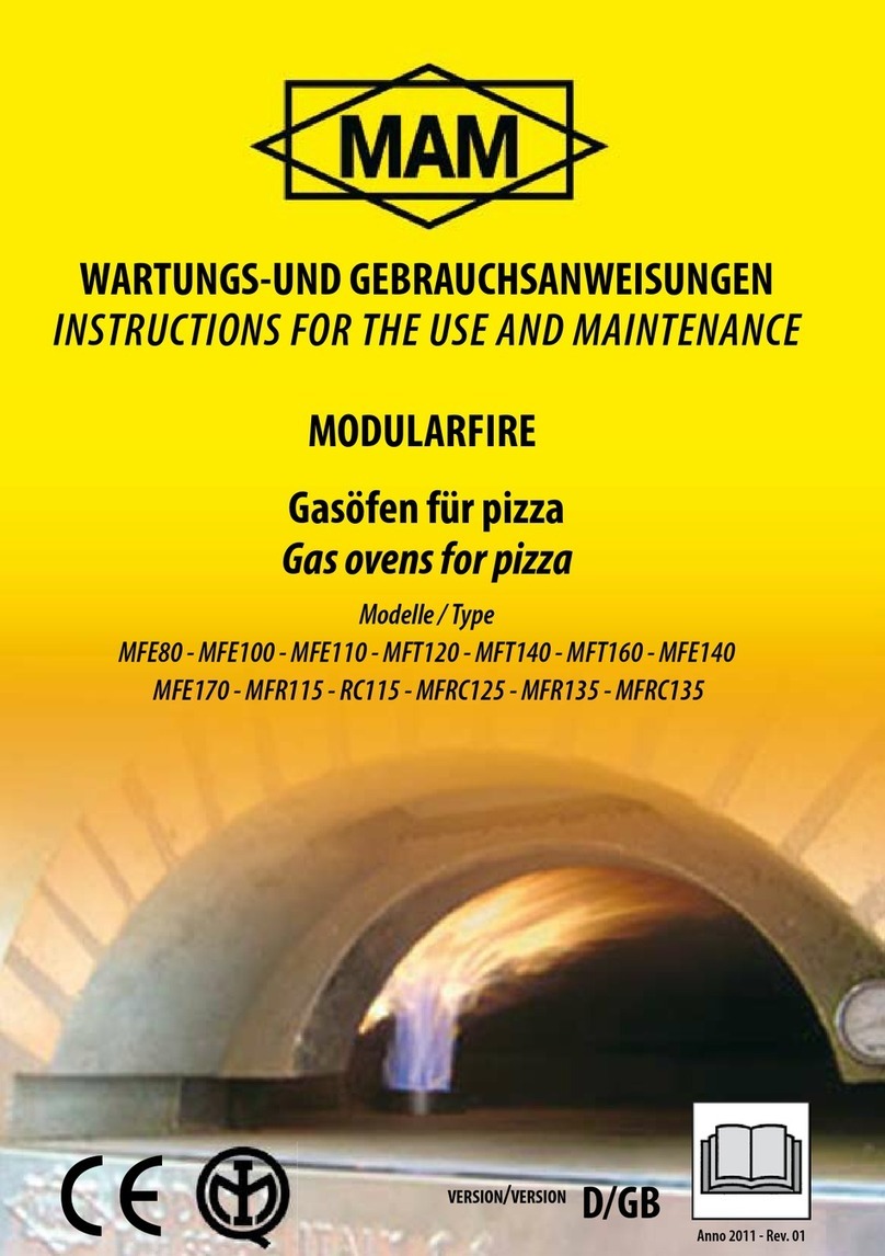
MAM MF3.1RG/C 120 Specification sheet

Forni a gas per pizza
Gas ovens for pizza
Modello / Type
MF3.1RG/C 120 -140 -160 - 170 - 180
MF2.1RG/C 80 - 100 - 110 - 120 - 140 - 160 - 170 - 180
MF3G/C 110 - 120 - 140 - 160 - 170 - 180
MF3EG/C 110 - 120 - 140 - 160 - 170 - 180
MF3RG/C 110 - 120 - 140 - 160 - 170 - 180
MF2G/C 110 - 120 - 140 - 160 - 170 - 180
MF2EG/C 110 - 120 - 140 - 160 - 170 - 180
MF2RG/C 110 - 120 - 140 - 160 - 170 - 180
MF1G/C 80 - MF1EG/C 80 - MF1RG/C 80
ISTRUZIONI PER L’USO E LA MANUTENZIONE
INSTRUCTIONS FOR THE USE AND MAINTENANCE
MODULARFIRE
Anno 2019 - Rev. 00

MANUALE D’USO
OPERATION MANUAL
Bruciatore a Gas • Gas Burner

3
INDICE INDEX
1 USO
1.1 Messa in funzione
1.2 Descrizione comandi consolle
1.3 Allarmi
1.4 Accensione e utilizzo del bruciatore
In modalità automatico
1.5 Accensione e utilizzo del bruciatore
In modalità manuale
1.6 Utilizzo del boost
1.7 Anomalia accensione del bruciatore
in modalità automatico / manuale
1.8 Spegnimento bruciatore
1.9 Partenza aut. programmata
1.10 Utilizzo cottura
2 MANUTENZIONE
2.1 Condizioni di sicurezza
durante la manutenzione
2.2 Pulizia e manutenzione
2.3 Pulizia ugelli gas
2.4 Sostituzione sonda temperatura
2.5 Risoluzione problemi
3 DISINSTALLAZIONE SMALTIMENTO
3.1 Disinstallazione
3.2 Smaltimento
1 OPERATION
1.1 Start-up
1.2 Control console description
1.3 Allarms
1.4 Burner ignition and use
in automatic mode
1.5 Burner ignition and use
in manual mode
1.6 Using the boost function
1.7 Faults with burner ignition
in automatic / manual mode
1.8 Turning o the burner
1.9 Programmed auto start
1.10 Cooking
2 MAINTENANCE
2.1 Safety conditions
during maintenance
2.2 Cleaning and maintenance
2.3 Gas nozzle cleaning
2.4 Temperature sensor replacement
2.5 Troubleshooting
3 DISASSEMBLY AND DISPOSAL
3.1 Disassembly
3.2 Disposal

4
Sezione 1
USO
Section 1
OPERATION
1.1
MESSA IN FUNZIONE
Prima di avviare il bruciatore controllare
che nulla ostruisca l’alusso dell’aria al
bruciatore e che la bocca del bruciatore
non sia in alcun modo tappata
1. Controllare che tutti i rubinetti del gas
siano aperti,sfiatare la tubazione del gas
se necessario.
2. Inserire un manometro sulla presa di
pressione del bruciatore e controllare sia
eventuali perdite di combustibile
(chiudendo l’immissione del gas) che la
corretta pressione del gas stesso, sia a
bruciatore spento che in funzione.
3. Accendere la centralina di comando
con il pulsante on /o in manuale.
1.1
START-UP
Before starting up the burner, ensure that
there are no obstructions on the air flow
to the burner and that the burner outlet is
not clogged.
1. Check that all gas valves
are open and bleed the gas pipelines
if necessary.
2. Insert a gauge on the burner pressure
outlet and check for any leaks of fuel
(shutting of gas delivery),
and that gas pressure is correct
both with the burner operating
and when switched o.
3. Turn on the control unit with
the on/o button in manual mode.
1) ATTENZIONE
Prima di avviare
il bruciatore
controllare
che nulla ostruisca
l’alusso dell’aria
alla bocca del forno.
2) ATTENZIONE
Prima di avviare
il bruciatore
controllare
che nulla ostruisca
l’alusso dell’aria
al bruciatore.
1) CAUTION
Before starting up
the burner, ensure
that there are no
obstructions
to the air flow
to the oven outlet.
2) CAUTION
Before starting
up the burner,
ensure that there
are no obstructions
to the air flow
to the burner.
1
2

5
1.2
DESCRIZIONE COMANDI
Sul pannello frontale del bruciatore sono
disposti i comandi per attivare le funzioni
principali.
1.2
DESCRIPTION OF CONTROLS
The front panel of the burner is fitted with
controls for the main functions.
BURNER IGNITION
Button to ignite or turn o the burner
• ON /OFF function
ACCENSIONE BRUCIATORE
Pulsante per L’accensione e lo spegnimento
del bruciatore • Funzione ON /OFF
ON
OFF

6
USING THE BURNER
IN AUTO MODE WITH T°
THRESHOLD CONTROL
Button to activate automatic temperature
control mode when the set temperature
is reached, programmable by means of
buttons (+ / -). In AUTO mode, the message
“AUTO ” appears on the multifunction
display. The buttons (+ / -) scan be used to
increase or decrease the burner operation
temperature value in °C.
This value is always shown on at the top
le of the display.
If the temperature exceeds the setting
by 10 degrees, the burner switches
o automatically to enable the
temperature to lower.
MANUAL FLAME
CONTROL FUNCTION
This button activates the MANUAL mode,
and the “hand” symbol appears
at the top le of the display.
In this mode the buttons (+ / -) always
enabled can be used to adjust the flame
power, with respective signal on the flame
power display, by means lit bars
indicating intensity.
TIMED MAXIMUM
BOOST POWER
This activates maximum burner power
with relative signal “Boost” on the
multifunction display (at top le) for the
time interval set by means of the buttons
(+ / -) from a minimum of 1 min. to a
maximum of 9 min., displayed alongside
the message “boost”. During this function,
the buttons (+ / -) can be used to increase
or decrease the time at any moment.
Egg timer symbol alongside active cursor.
Once the time interval has elapsed,
the previous conditions are restored
automatically. The time set in the previous
cycle is restored on the subsequent cycle.
This timed function can be activated both
in auto and manual mode.
UTILIZZO DEL BRUCIATORE
IN MODALITÀAUTO
CON CONTROLLO SOGLIA T°
Pulsante per l’inserimento modalità
automatica termoregolazione al
raggiungimento della temperatura
impostata programmabile per mezzo dei
pulsanti (+ / -). In modalità AUTO compare
la scritta “AUTO ” sul display multifunzione.
Agendo sui pulsanti (+ / -) si incrementa o
decrementa il valore della temperatura
di utilizzo del bruciatore °C. Valore sempre
visibile sul display in alto a sinistra.
Al superamento di 10 gradi dalla
temperatura impostata il bruciatore
si spegne automaticamente per
permettere l’abbassamento della
temperatura.
FUNZIONE CONTROLLO
FIAMMA MANUALE
Premendo il pulsante si attiva la funzione
mod. MANUALE comparirà il simbolo
“mano” in alto a sinistra del display.
In questa modalità si regola manualmente
tramite i pulsanti (+ / -) sempre attivi,
l’intensità della fiamma con rispettiva
segnalazione su display intensità
fiamma mediante cursore d’intensità
a barre illuminate.
BOOST MASSIMA POTENZA
TEMPORIZZATA
Premendo si attiva la massima potenza
del bruciatore con relativa accensione
della scritta “ Boost” sul display multif.
(in alto a sinistra) per il tempo impostabile
tramite i pulsanti (+ / -) da un minimo di
1 min. ad un max di 9 min., visualizzabile
a fianco della scritta boost. Durante
questa funzione i tasti (+ / -) potranno
incrementare o diminuire il tempo
costantemente. Simbolo clessidra a fianco
del cursore attivo. Una volta terminato il
tempo si ripristinano le condizioni presenti
prima dell’attivazione della medesima.
Il tempo impostato nel ciclo precedente
viene riproposto al ciclo successivo.
Questa funzione di tipo temporaneo può
essere attivata sia dalla condizione di aut.
che di man.
AUTO
MAN
BOOST

7
BURNER BLOCK RESET
Button used to unblock the burner in the
event of failure of flame ignition
KEEP BUTTON PRESSED FOR
AT LEAST 1 sec.
PROGRAMMED
AUTO START ACTIVATION
This button displays (centre display) the
flame symbol alongside the clock symbol,
while the countdown time for delayed
start-up is shown at the top right of the
display (expressed in hours/min).
The buttons (+ / -) can be used to increase
or decrease the time in intervals of 0.5h to
a maximum of 48h and minimum of 0.5h.
10 sec. before start-up, the buzzer
is sounded each second for 3 seconds,
aer which it sounds continuously
through to start-up. The time set in
the previous cycle is restored on the
subsequent automatic cycle.
INCREASE DISPLAY VALUE
This button increases the value shown
on display according to the previously
enabled function. This button gradually
increases the value and when pressed
for a few seconds increases the value
exponentially. On release of the button,
the value is stored in the memory
without the need for confirmation.
When the unit is turned o but still
powered, the button increases the current
time (at top right of display).
DECREASE DISPLAY VALUE
This button decreases the value shown
on display according to the previously
enabled function. This button gradually
decreases the value and when pressed
for a few seconds increases the value
exponentially. On release of the button,
the value is stored in the memory without
the need for confirmation. When the unit
is turned o but still powered, the button
decreases the current time (at top right
of display).
RESET BLOCCO BRUCIATORE
Pulsante per lo sblocco del bruciatore
in caso di mancata accensione fiamma
TENERE PREMUTO IL PULSANTE
PER ALMENO 1 sec.
INSERIMENTO PARTENZA
AUT. PROGRAMMATA
Premendo il pulsante si visualizza
(al centro del display) il simbolo della
fiamma a fianco del simbolo orologio
mentre in alto a destra del display il
tempo mancante (espresso in ore/min)
per la partenza ritardata. Agendo sui
pulsanti (+ / -) si incrementa o decrementa
di 0,5h sino ad un massimo di 48h ed
un minimo do 0.5h. 10 sec. prima della
partenza il cicalino avviserà con un beep
ad ogni secondo sino a 3 secondi dopo
di che diventerà un suono continuo sino
all’avviamento. Il tempo impostato
nel ciclo precedente viene riproposto
al ciclo successivo automatico.
INCREMENTA VALORE DISPLAY
Premendo il pulsante si incrementa
il valore visualizzato nel display
determinato dalla funzione
precedentemente attivata. Il tasto
incrementa lentamente e dopo alcuni
secondi aumenta di valore in maniera
esponenziale. Una volta rilasciato
il pulsante il dato rimane in memoria
senza la necessità di conferma.
A terminale spento ma alimentato
il tasto incrementa l’ora corrente
(in alto a destra del display).
DECREMENTA VALORE DISPLAY
Premendo il pulsante si decrementa
il valore visualizzato nel display
determinato dalla funzione
precedentemente attivata. Il tasto
decrementa lentamente e dopo alcuni
secondi aumenta di valore in maniera
esponenziale. Una volta rilasciato
il pulsante il dato rimane in memoria
senza la necessità di conferma. A
terminale spento ma alimentato il tasto
decrementa l’ora corrente (in alto
a destra del display).
R
+
_

8
CURRENT ITEMS SHOWN ON
MULTIFUNCTION DISPLAY
• Current time
• Burner temperature
• Set temperature
• Burner block symbol
• Manual mode
• Automatic mode
• Burner lit symbol ( flame )
• Flame power via cursor
• Boost function and relative set time
and egg timer symbol indicating
current function
• Clock symbol and flame symbol
indicating start-up delay activated
with time countdown display.
• Sensor disconnected symbol
SETTING DISPLAY
When the burner is o, the buttons
(+ / -) can be used to set the time
1.3 ALARMS
The burner has been blocked:
press button R to release and
KEEP PRESSED FOR AT LEAST 3sec.
Temperature sensor short circuit:
REPLACE SENSOR
Sensor disconnected:
CHECK THAT the connector
plug has not been detached.
CAUTION
on activation of alarm 1 and 2
the burner switches automatically
to MANUAL mode.
VISUALIZZAZIONI CORRENTI
SU DISPLAY MULTIFUNZIONE
• Ora corrente
• Temperatura bruciatore
• Temperatura impostata
• Simbolo blocco bruciatore
• Modalità manuale
• Modalità automatico
• Simbolo bruciatore acceso ( fiamma )
• Intensità fiamma mediante cursore
• Funzione boost e relativo tempo
impostato e simbolo clessidra
funzione in corso
• Simbolo orologio e fiamma funzione
partenza anticipata attivata con
visualizzazione tempo rimanente.
• Simbolo sonda interrotta
IMPOSTAZIONE OROLOGIO
Con il bruciatore spento tramite
i pulsanti (+ / -) si imposta l’orario
1.3 ALLARMI
Il bruciatore è in blocco:
spingere il tasto Rper sbloccarlo e
TENERLO PREMUTO PER ALMENO 3 sec.
Sonda temperatura in corto:
SOSTITUIRE LA SONDA
Sonda interrotta:
CONTROLLARE che la spina
di connessione non sia staccata.
ATTENZIONE
con il verificarsi dell’allarme 1 e 2
il bruciatore passa automaticamente
in modalità MANUALE.
DISPL AY
X
X
1
X
2

9
ICONA FIAMMA - FLAME ICON
TEMPERATURA IMPOSTATA FORNO
SET OVEN TEMPERATURE
TEMPERATURA FORNO
OVEN TEMPERATURE
Premere il pulsante ON/OFF
per accendere il bruciatore.
Premere il pulsante AUTO e
attendere l’innesco della fiamma.
Regolare la temperatura di lavoro
del forno con i pulsanti (+/-).
La temperatura del forno sarà
quella visualizzata nel monitor.
Press the ON/OFF button
to ignite the burner.
Press the AUTO button and
wait for the flame to ignite.
Adjust the oven operating
temperature using the buttons (+/-).
The oven temperature
is that set on screen.
1.4
ACCENSIONE E UTILIZZO DEL
BRUCIATORE IN MODALITÀ
AUTOMATICO
1.4
BURNER IGNITION AND USE
IN AUTOMATIC MODE
ON
OFF
AUTO

10
ICONA FIAMMA - FLAME ICON
INTENSITÀ FIAMMA - FLAME POWER
TEMPERATURA FORNO
OVEN TEMPERATURE
Premere il pulsante ON/OFF
per accendere il bruciatore.
Premere il pulsante MAN e
attendere l’innesco della fiamma.
Regolare la temperatura di lavoro
del forno con i pulsanti (+/-).
La temperatura del forno sarà
quella visualizzata nel monitor.
Press the ON/OFF button
to ignite the burner.
Press the MAN button and
wait for the flame to ignite.
Adjust the oven operating
temperature using the buttons (+/-).
The oven temperature
is that set on screen.
1.5
ACCENSIONE E UTILIZZO
DEL BRUCIATORE IN
MODALITÀ MANUALE
1.5
BURNER IGNITION AND USE
IN MANUAL MODE
ON
OFF
MAN

11
1.6
UTILIZZO DEL BOOST
1.7
ANOMALIA ACCENSIONE DEL
BRUCIATORE IN MODALITÀ
AUTOMATICO / MANUALE
Premere il pulsante di RESET
mantenendolo premuto per 10 secondi
e attendere che la scala graduata
vada a esaurirsi.
1.6
USING THE BOOST FUNCTION
1.7
FAULTS WITH BURNER
IGNITION IN AUTOMATIC /
MANUAL MODE
Press the RESET button for 10 seconds
and wait for the
graduated scale to run out.
R
BOOST
TEMPO DI DURATA BOOST
BOOST DURATION
ANOMALIA ACCENSIONE
IGNITION FAULT
SCALA GRADUATA
GRADUATED SCALE
BOOST
Premere i pulsanti (+/-)
per impostare il tempo di durata
del BOOST.
Premendo il pulsante BOOST si
attiva la massima potenza del
bruciatore con relativa accensione
della scritta “Boost” sul display.
Press buttons (+/-)
to set the duration of the
BOOST function.
The BOOST button activates
maximum burner power
with relative signal “Boost”
on the display.
Se non avviene l’accensione del bruciatore
sul display appare l’immagine
della fiamma contrassegnata da una X.
If burner ignition fails, the
flame symbol appears on the display
with the symbol X.

12
1.8
SPEGNIMENTO BRUCIATORE
1.9
PARTENZA AUTOMATICA
PROGRAMMATA
Agendo sui pulsanti (+/-) si imposta il tempo
di attesa prima che parta il bruciatore.
1.8
TURNING OFF THE BURNER
1.9
PROGRAMMED
AUTO START
The buttons (+/-) can be used to set the
wait time before starting up the burner.
ON
OFF
+
_
Premere il pulsante ON/OFF,
attendere lo spegnimento e verificare
sul display l’icona.
Con il bruciatore spento, impostare
l’ora corrente premendo i pulsanti (+/-)
verificando sul display.
Press the ON/OFF button and wait
for the burner to turn o, confirmed
by the relative icon on display.
With the burner o, set the current time
using the buttons (+/-) checking the
correct setting on display.
ICONA SPEGNIMENTO
BURNER OFF ICON
ORA - TIME
TEMPO - TIME
ICONA - ICON
Premendo il pulsante con il simbolo
dell’orologio si visualizza l’icona.
When the button with the clock symbol
is pressed, the relative icon is displayed.

13
1.10
UTILIZZO COTTURA
1. IN MODALITÀ MANUALE
•Accendere il bruciatore premendo
il tasto ON / OFF
•Premere il tasto MAN
•Alzare la fiamma al massimo della
potenza per fare riscaldare il forno
fino alla temperatura desiderata
•Una volta che è stata raggiunta
la temperatura desiderata abbassare
tramite il tasto “–“ la potenza della
fiamma per stabilizzare la temperatura,
poi manualmente alzare ed abbassare
la potenza della fiamma tramite
il tasto “+“ e “-” per mantenere
la temperatura desiderata.
2. IN MODALITÀ AUTOMATICA
•Accendere il bruciatore premendo
il tasto ON / OFF
•Premere il tasto AUT
•Impostare i gradi desiderati
tramite i tasti + e –
•Attendere che il bruciatore porti
a temperatura il forno, a questo punto
la fiamma si abbasserà gradatamente
fino ad arrivare al minimo
•A questo punto si possono infornare le pizze
•Con questa funzione automatica si vedrà
la fiamma del bruciatore che in modo
modulare alzerà ed abbasserà la fiamma
per mantenere la temperatura prescelta
NOTA BENE
Per una cottura omogenea e sconsigliabile
infornare le pizze prima che il forno sia arrivato
in temperatura.
1.10
COOKING
1. IN MANUAL MODE
•Ignite the burner using the
ON / OFF button
•Press the MAN button
•Increase the flame to maximum
power to heat the oven
to the required temperature
•Once the required temperature is reached,
lower the flame setting using the “–“
button to stabilise the temperature,
then manually increase and decrease
the flame power using the buttons
“+“ and “-” to maintain
the required temperature.
2. IN AUTOMATIC MODE
•Ignite the burner using the ON / OFF button
•Press the AUT button
•Set the required degrees using
the buttons + and –
•Wait for the burner to bring the oven
to the correct temperature; at this point
the burner gradually decreases
to minimum level
•The pizzas can now be placed in the oven
•In automatic mode, the burner modulates
the flame power (up or down) to maintain
the selected temperature
N.B.
To ensure uniform cooking, avoid placing
the pizzas in the oven before the correct
temperature has been reached.

14
Sezione 2
MANUTENZIONE
Section 2
MAINTENANCE
MANUTENZIONE
Contattare la ditta, il rappresentante della
ditta oppure una società di servizi locale per
eettuare la manutenzione e le riparazioni.
2.1
CONDIZIONI DI SICUREZZA
DURANTE LA MANUTENZIONE
Per garantire una condizione suiciente
di sicurezza sul lavoro, è necessario che
l’operatore osservi i seguenti punti:
• QUALSIASI operazione di manutenzione
dell’apparecchiatura deve essere eseguita da
personale QUALIFICATO ed AUTORIZZATO.
• OGNI tipo di intervento di manutenzione
all’apparecchiatura deve essere eseguita
senza tensione , verificando che sia stata
preventivamente disalimentata dalla corrente
elettrica (se prevista).
• NON ESEGUIRE interventi di manutenzione
in presenza di acqua.
• ACCERTARSI che la zona in cui si svolgano
le operazioni di manutenzione, sia PULITA ed
ASCIUTTA.
• INDOSSARE esclusivamente capi approvati
ai fini ANTINFORTUNISTICI.
2.2
MANUTENZIONE EPULIZIA
CONTROLLI DA ESEGUIRE OGNI 6 MESI:
da parte di tecnico qualificato e autorizzato.
1 Fissaggio del bruciatore al forno
Controllare il serraggio dei bulloni di
fissaggio della flangia di supporto al forno.
2 Fissaggio della flangia regolabile
Controllare il serraggio della fascietta
metallica stringitubo.
MAINTENANCE
Contact the manufacturer, an appointed
representative or a local services company
to perform maintenance and repairs.
2.1
SAFETY CONDITIONS
DURING MAINTENANCE
To ensure adequate safety conditions
at work, the operator must observe the
following points:
• ALL maintenance operations on the
equipment must be performed by QUALIFIED
and AUTHORISED personnel.
• ALL maintenance operations must be
performed without live components,
ensuring that the mains electricity has been
disconnected beforehand (if envisaged).
• NEVER PERFORM maintenance in the
presence of water.
• ENSURE that the maintenance work
area is CLEAN and DRY.
• WEAR exclusively clothing approved and
compliant with SAFETY STANDARDS.
2.2
CLEANING AND
MAINTENANCE
CHECK EVERY 6 MONTHS:
by qualified and authorised technician.
1 Fixture of burner on oven
Check tightening of fixing bolts on the
support flange connected to the oven.
2 Fixture of adjustable flange
Check tightening of the
metal pipe clamping clip.

15
3 Controlli attacchi gas
Verificare il serraggio del raccordo gas
alla valvola.
Verificare il serraggio del raccordo gas al
collettore del bruciatore.
Verificare che la presa di pressione su
collettore gas sia serrata correttamente.
4 Verifica eventuali perdite di gas
Spruzzare lo spry ( rilevatore fughe di gas)
sui raccordi gas e prese di pressione,
vedere se si formano delle bolle, segnale di
perdita di gas. Se Si ricontrollare il serraggio
dei raccordi ed eventualmente sostituirli.
L’apparecchiatura deve essere pulita per
garantire una funzionalità corretta e duratura
nel tempo oltre una perfetta igiene.
Pulizia dell’impianto:
eseguire e rispettare le seguenti operazioni
ed avvertenze:
• assicurarsi che il rubinetto gas a monte sia
chiuso e che tutti i bruciatori siano spenti;
• fare rareddare l’apparecchiatura;
• Soiare il tubo-venturi del bruciatore con
aria compressa o aspirare con aspirapolvere;
solo con valvola staccata. IMPORTANTE
• non lavare mai l’apparecchiatura con getti di
acqua diretti ad alta pressione.
3 Gas fitting checks
Check tightening of gas fitting to valve.
Check tightening of gas fitting
to burner manifold.
Check that the pressure socket on the gas
manifold is tightened correctly.
4 Check for possible gas leaks
Spray the gas leak detector fluid on the gas
fittings and pressure sockets, and check
whether bubbles form, indicating a gas leak.
If bubbles are detected, re-check tightening
of fittings and replace if necessary.
The equipment must be cleaned regularly to
ensure optimal eiciency and prolonged lifetime,
as well as to guarantee perfect hygiene.
System cleaning:
For system cleaning, take care to follow and
observe the following operations and warnings:
• ensure that the gas valve upline is closed
and that all burners are turned o;
• let the equipment cool;
• Clean the Venturi pipe of the burner with
compressed air or vacuum clean;
perform only with valve DETACHED.
IMPORTANT:
• never wash the equipment with direct high
pressure water jets;
2.3
PULIZIA UGELLI GAS
Pulire periodicamente il bruciatore nella
zona H da eventuale polvere usando aria
compressa (vedi fig. 9.3 soiare zona H).
2.3
GAS NOZZLE CLEANING
Periodically clean the burner in zone H to
remove any dust, using compressed air (see
fig. 9.3 zone H cleaning with compressedir).
fig. 9.3
H

16
2.4
SOSTITUZIONE SONDA
TEMPERATURA
Prestare particolare attenzione durante le
operazionidisostituzionedellasonda,accertarsi
che il bruciatore sia spento e che la temperatura
del forno non sia superiore a 40°C.
Eseguire le seguenti operazioni:
• Togliere l’eventuale isolamento
in prossimità della sonda
• Sfilare il bulbo termostatico
nella cupola del forno
• Smontare il bulbo dalla valvola
• Infilare il nuovo bulbo nella cupola
del forno
• Montare in nuovo bulbo nel pannello
operatore
• Ripristinare l’eventuale isolamento
Se i dispositivi di accensione e controllo
dovessero presentare diicoltà nella
manovrabilità, contattate immediatamente
il produttore che provvederà alla manutenzione.
Occorre fare controllare l’apparecchiatura
almeno una volta l’anno e per questo motivo
si consiglia di sottoscrivere un contratto di
assistenza. È necessario far controllare che gli
orifizi delle fiamme siano sempre puliti.
Tutte le operazioni di manutenzione e di
riparazione devono essere eettuate da
personale autorizzato e qualificato.
2.4
TEMPERATURE SENSOR
REPLACEMENT
Pay specialattention duringsensorreplacement,
ensuring that the burner is turned o and that
the oven temperature is below 40°C.
Proceed as follows:
• Remove any insulation
close to the sensor
• Extract the thermostat bulb
in the oven dome
• Disassemble the bulb from the valve
• Insert the new bulb
in the oven dome
• Fit the new bulb in the operator panel
• Restore any removed insulation
If the ignition and control devices
are diicult to handle,
contact the manufacturer immediately
for appropriate maintenance.
Check the equipment at least once a
year. For this procedure the manufacturer
recommends stipulating a services contract.
Check that all flame orifices are clean at all
times.
All maintenance and repair operations
must be performed by authorised and
qualified personnel.

17
2.5
RISOLUZIONE PROBLEMI
Se il quadro di comando non si
accende:
1. Controllare che il fusibile sull’interruttore
del filtro non sia interrotto.*
2. Controllare che il fusibile all’interno del
pannello operatore non sia interrotto.*
*(vedi Allegato 8 - manuale Installazione)
Se il bruciatore va in blocco:
1. Controllare che la bocca del bruciatore
non sia ostruita
2. Controllare che il gas arrivi correttamente.
3. Controllare che non ci siano delle correnti
d’aria che possano disturbare il corretto
funzionamento del bruciatore.
4. Controllare che le boccole di regolazione
dell’aria non siano completamente chiuse.
5. Controllare che la valvola sia in posizione
verticale.
6. Verificare il funzionamento del tiraggio del
camino.
Se non si accende il bruciatore:
1. Verificare che non sia intervenuto il sensore
fumi, dovuto al mal funzionamento della canna
fumaria.
2. Potrebbe essere caduto dello sporco (fuliggine,
farina, pasta della pizza ecc.) in prossimità dei
dispositivi di accensione e di rilevazione fiamma
per pulirlo proseguire come segue:
A. Chiudere il rubinetto del gas.
B. Da sotto al bruciatore svitare i bulloni che
fissano il bruciatore alla base del bruciatore.
C. Sfilare il bruciatore verso il basso
( facendo attenzione a non piegare o
rompere i dispositivi di accensione e di
rilevazione fiamma) ed estrarlo dal foro.
2.5
TROUBLESHOOTING
If the control panel
does not turn on:
1. Check that the fuse on the filter switch,
has not blown.*
2. Check that the fuse inside the operator
panel has not blown.*
*(see Annex 8 - Installation manual)
If the burner blocks:
1. Check that the burner outlet
is not blocked
2. Check that gas is delivered correctly.
3. Check that there are
no air draughts that
could impair burner eiciency
4. Check that the air flow adjuster nuts are
not completely closed.
5. Check that the valve is in the vertical
position.
6. Check eiciency of the flue draught.
If the burner does not ignite:
1. Check that the flue gas sensor
has not tripped, due to malfunction
of the flue.
2. Some dirt (soot, flour, pizza dough, etc.)
may have fallen around
the ignition or flame detection devices.
To clean, proceed as follows:
A. Close the gas valve.
B. Loosen the bolts under the burner
securing the burner to the base.
C. Gently pull the burner downwards
( taking care not to bend or break
the ignition and flame detection devices)
and remove from the hole.

18
D. Rimuovere l’eventuale sporco
dal bruciatore (consigliamo di soiarlo
con aria compressa)
E. Controllare che la distanza degli elettrodi
rispetto i collettori dei bruciatori sia corretta
(vedi Allegato 5 – - MAN. ISTALLAZIONE)
F. Reinserire il bruciatore nella posizione
precedente e fissarlo correttamente.
Se i problemi persistono contattare
il centro assistenza.
Se la fiamma è troppo bassa:
1. Verificare che il bruciatore sia configurato con
il tipo di alimentazione corretta.
Alimentazione a metano – ugelli e regolazione
aria primaria per il metano.
Alimentazione a GPL – ugelli e regolazione aria
primaria per il gpl.
Se la fiamma è troppo gialla:
1. Verificare che la regolazione
dell’aria primaria sia corretta
(vedi Tab. 7.8 - MAN. ISTALLAZIONE)
in relazione al tipo di alimentazione e
configurazione del bruciatore.
2. Eventualmente incrementare
leggermente la distanza H
(vedi Tab. 7.8 - MAN. ISTALLAZIONE)
sino ad ottenere una fiamma Ideale in cui
solo la parte superiore della fiamma è gialla.
Se la fiamma è troppo blu:
1. Verificare che la regolazione
dell’aria primaria sia corretta
(vedi Tab. 7.8 - MAN. ISTALLAZIONE)
in relazione al tipo di alimentazione e
configurazione del bruciatore
2. Eventualmente abbassare
leggermente la distanza H
(vedi Tab. 7.8 - MAN. ISTALLAZIONE)
sino ad ottenere una fiamma Ideale.
D. Remove any dirt from the burner
(the use of compressed air
is recommended)
E. Check that the distance of the electrodes
from the burner manifolds is correct
(see Annex. 5 - INSTALLATION MAN.)
F. Refit the burner in its position
and secure in place. If problems persist,
contact the assistance centre.
If the flame is too low:
1. Ensure that the burner is configured for
the correct type of fuel supply.
Natural gas supply - nozzles and primary
air for natural gas.
LPG supply - nozzles and primary
air for LPG.
If the flame is too yellow:
1. Check that the primary air setting is correct
(see Tab. 7.8 - INSTALLATION MAN.)
according to the type of fuel
and configuration of the burner.
2. If necessary, slightly increase distance H
(see Tab. 7.8 - INSTALLATION MAN.)
to obtain the ideal flame, i.e. where only
the tip of the flame is yellow.
If the flame is too blue:
1. Check that the primary air setting is correct
(see Tab. 7.8 - INSTALLATION MAN.)
according to the type of fuel and
configuration of the burner.
2. If necessary, slightly decrease distance H
see (see Tab. 7.8 - INSTALLATION MAN.)
to obtain the ideal flame.

19
3.1
DISINSTALLAZIONE
Conclusa la vita lavorativa del bruciatore è
necessario procedere alla disinstallazione
e allo smontaggio;
TUTTE LE OPERAZIONI DI SMONTAGGIO
DELLA MACCHINA DEVONO ESSERE
EFETTUATE DA PERSONALE QUAL IFICATO
E NELL ’OSSERVANZA DELLE NORME DI
SICUREZZA.
Pertanto È OBBLIGATORIO che durante la fase
di smontaggio vengano indossati i seguenti
dispositivi di protezione individuale: Pertanto,
nelle operazioni di smontaggio, bisogna valutare
i RISCHI RESIDUI successivamente descritti:
• SCHIACCIAMENTO
• CADUTE MATERIALI
• TAGLI
• ABRASIONI
3.2
SMALTIMENTO
Dopo lo smontaggio, è necessario che avvenga
una suddivisione della componentistica
del bruciatore in funzione dei materiali di
composizione; successivamente provvedere allo
smaltimento presso gli ENTI AUTORIZZATI, nel
pieno rispetto delle norme vigenti in materia di
rifiuti.
3.1
DISASSEMBLY
At the end of the burner lifetime, it should be
disassembled and disposed of;
ALL MACHINE DISASSEMBLY OPERATIONS
MUST BE PERFORMED BY QUALIFIED
PERSONNEL IN OBSERVANCE OF CURRENT
SAFETY STANDARDS.
It is therefore COMPULSORY during disassembly
procedures, to use the following personal
protective equipment: During disassembly,
the following RESIDUAL RISKS must also be
taken into account:
• CRUSHING
• FALLING MATERIALS
• CUTS
• ABRASIONS
3.2
DISPOSAL
Aer disassembly, the burner components
need to be divided according to materials
for subsequent disposal and AUTHORISED
DISPOSAL FIRMS, in full compliance with
current waste disposal regulations.
Sezione 3
DISINSTALLAZIONE
SMALTIMENTO
Section 3
DISASSEMBLY
AND DISPOSAL

20
ALLEGATI AL MANUALE ANNEXES TO THE MANUAL
ALLEGATO 10
DIMENSIONI IMBALLO E PACKING LIST
ALLEGATO 11
TARGHETTA IMBALLO
ALLEGATO 12
DICHIARAZIONE DI CONFORMITÀ
ALLEGATO 13
GARANZIA
ALLEGATO 14
CERTIFICAZIONI DI CONFORMITÀ
ANNEX 10
PACKAGING DIMENSIONS AND PACKING LIST
ANNEX 11
PACKAGING DATA PLATE
ANNEX 12
DECLARATION OF CONFORMITY
ANNEX 13
WARRANTY
ANNEX 14
CERTIFICATIONS OF COMPLIANCE
This manual suits for next models
45
Table of contents
Other MAM Oven manuals
Popular Oven manuals by other brands

Brandt
Brandt FC 222 user manual
aumate
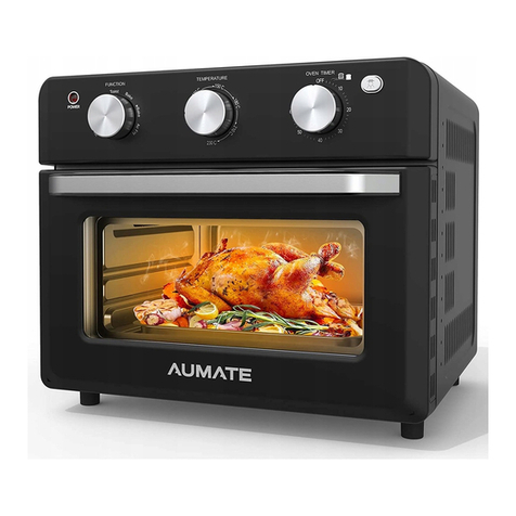
aumate TOA20M04N-1E instruction manual
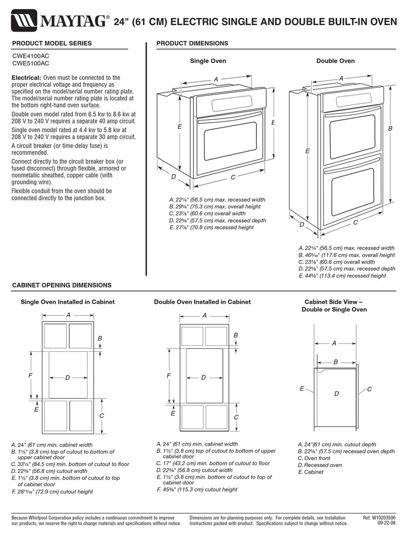
Maytag
Maytag CWE4100AC - 24" Single Electric Wall Oven Dimension Guide
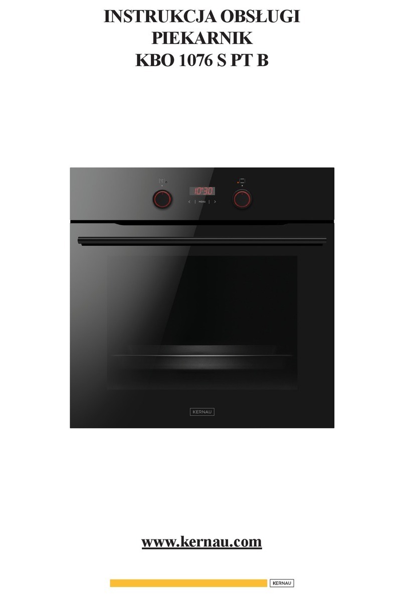
Kernau
Kernau KBO 1076 S PT B instruction manual

Bosch
Bosch HB 37 N Series User manual and installation instructions

Electrolux
Electrolux EOD5420AA user manual
