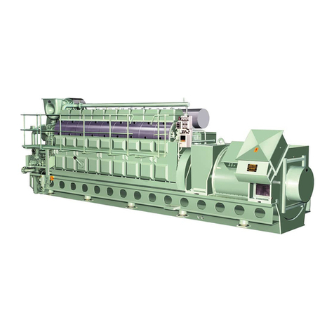
MAN B&W S65ME-C8.2-GI-TII User manual

MAN B&W S65ME-C8.2-GI 199 02 43-1.0
This Project Guide is intended to provide the information necessary for the layout of a marine propulsion
plant.
The information is to be considered as preliminary. It is intended for the project stage only and subject to
modification in the interest of technical progress. The Project Guide provides the general technical data
available at the date of issue.
It should be noted that all figures, values, measurements or information about performance stated in this
project guide are for guidance only and should not be used for detailed design purposes or as a substi-
tute for specific drawings and instructions prepared for such purposes.
Data updates
Data not finally calculated at the time of issue is marked ‘Available on request’. Such data may be made
available at a later date, however, for a specific project the data can be requested. Pages and table entries
marked ‘Not applicable’ represent an option, function or selection which is not valid.
The latest, most current version of the individual Project Guide sections are available on the Internet at:
www.marine.man.eu → ’Two-Stroke’.
Extent of Delivery
The final and binding design and outlines are to be supplied by our licensee, the engine maker, see Chap-
ter 20 of this Project Guide.
In order to facilitate negotiations between the yard, the engine maker and the customer, a set of ‘Extent of
Delivery’ forms is available in which the basic and the optional executions are specified.
Electronic versions
This Project Guide book and the ‘Extent of Delivery’ forms are available on the Internet at:
www.marine.man.eu → ’Two-Stroke’, where they can be downloaded.
Edition 0.5
May 2014
MAN B&W S65ME-C8.2-GI-TII
Project Guide
Electronically Controlled
Dual Fuel Two-stroke Engines

MAN B&W S65ME-C8.2-GI 199 02 43-1.0
MAN Diesel & Turbo
Teglholmsgade 41
DK2450 Copenhagen SV
Denmark
Telephone +45 33 85 11 00
Telefax +45 33 85 10 30
mandiesel-cph@mandiesel.com
www.mandieselturbo.com
Copyright 2014 © MAN Diesel & Turbo, branch of MAN Diesel & Turbo SE, Germany, registered with the Danish
Commerce and Companies Agency under CVR Nr.: 31611792, (herein referred to as “MAN Diesel & Turbo”).
This document is the product and property of MAN Diesel & Turbo and is protected by applicable copyright laws.
Subject to modification in the interest of technical progress. Reproduction permitted provided source is given.
7020-0207-00ppr May 2014
All data provided in this document is non-binding. This data serves informational purposes only and is espe-
cially not guaranteed in any way.
&GRGPFKPIQPVJGUWDUGSWGPVURGEKǣEKPFKXKFWCNRTQLGEVUVJGTGNGXCPVFCVCOC[DGUWDLGEVVQEJCPIGUCPFYKNN
DGCUUGUUGFCPFFGVGTOKPGFKPFKXKFWCNN[HQTGCEJRTQLGEV6JKUYKNNFGRGPFQPVJGRCTVKEWNCTEJCTCEVGTKUVKEUQH
GCEJKPFKXKFWCNRTQLGEVGURGEKCNN[URGEKǣEUKVGCPFQRGTCVKQPCNEQPFKVKQPU
+HVJKUFQEWOGPVKUFGNKXGTGFKPCPQVJGTNCPIWCIGVJCP'PINKUJCPFFQWDVUCTKUGEQPEGTPKPIVJGVTCPUNCVKQPVJG
English text shall prevail.

MAN B&W
MAN Diesel
Engine Design ....................................................................... 1
Engine Layout and Load Diagrams, SFOC .............................. 2
Turbocharger Selection & Exhaust Gas By-pass .................... 3
Electricity Production ............................................................ 4
Installation Aspects ............................................................... 5
List of Capacities: Pumps, Coolers & Exhaust Gas ................. 6
Fuel ...................................................................................... 7
Lubricating Oil ...................................................................... 8
Cylinder Lubrication .............................................................. 9
Piston Rod Stuffing Box Drain Oil .......................................... 10
Central Cooling Water System ............................................... 11
Seawater Cooling System ..................................................... 12
Starting and Control Air ......................................................... 13
Scavenge Air ......................................................................... 14
Exhaust Gas .......................................................................... 15
Engine Control System .......................................................... 16
Vibration Aspects .................................................................. 17
Monitoring Systems and Instrumentation .............................. 18
Dispatch Pattern, Testing, Spares and Tools ........................... 19
Project Support and Documentation ...................................... 20
Appendix .............................................................................. A
Contents


MAN B&W Contents
Chapter Section
MAN Diesel
MAN B&W S65ME-C8.2-GI
1 Engine Design
The ME-GI dual fuel engine 1.00 1989151-6.1
The fuel optimised ME Tier II engine 1.01 1988537-1.4
Tier II fuel optimisation 1.01 1989158-9.0
Engine type designation 1.02 1983824-3.9
Power, speed, SFOC 1.03 1988987-5.1
Engine power range and fuel oil consumption 1.04 1984917-2.4
Performance curves 1.05 1985331-6.2
ME-GI Engine description 1.06 1988914-5.2
2 Engine Layout and Load Diagrams, SFOC
Engine layout and load diagrams 2.01 1983833-8.5
Propeller diameter and pitch, influence on optimum propeller speed 2.02 1983878-2.6
Layout diagram sizes 2.03 1988277-0.7
Engine layout and load diagrams 2.04 1986993-5.3
Diagram for actual project 2.05 1988329-8.1
Specific fuel oil consumption, ME versus MC engines 2.06 1988655-6.0
SFOC for high efficiency turbochargers 2.07 1988692-6.0
SFOC reference conditions and guarantee 2.08 1988341-6.1
Examples of graphic calculation of SFOC 2.08 1988634-1.0
SFOC calculations, example 2.10 1988418-5.0
Fuel consumption at an arbitrary load 2.11 1983843-4.5
3 Turbocharger Selection & Exhaust Gas Bypass
Turbocharger selection 3.01 1988728-8.0
Exhaust gas bypass 3.02 1984593-4.6
Emission control 3.03 1988447-2.2
4 Electricity Production
Electricity production 4.01 1984155-0.5
Designation of PTO 4.01 1985385-5.5
PTO/RCF 4.01 1984300-0.3
Space requirements for side mounted PTO/RCF 4.02 1984915-9.2
Engine preparations for PTO 4.03 1984315-6.3
PTO/BW GCR 4.04 1984316-8.8
Waste Heat Recovery Systems (WHRS) 4.05 1985797-7.5
WHRS generator output 4.05 1988922-8.0
WHR element and safety valve 4.05 1988288-9.1
L16/24-TII GenSet data 4.06 1988280-4.0
L21/31TII GenSet data 4.07 1988281-6.0
L23/30H-TII GenSet data 4.08 1988282-8.0
L27/38-TII GenSet data 4.09 1988284-1.0
L28/32H-TII GenSet data 4.10 1988285-3.0

MAN B&W Contents
Chapter Section
MAN Diesel
MAN B&W S65ME-C8.2-GI
5 Installation Aspects
Space requirements and overhaul heights 5.01 1984375-4.7
Crane beam for overhaul of turbochargers 5.03 1990018-0.0
Crane beam for turbochargers 5.03 1984848-8.3
Engine room crane 5.04 1984893-0.1
Overhaul with Double-Jib crane 5.04 1984534-8.4
Double-Jib crane 5.04 1984541-9.2
Engine outline, galleries and pipe connections 5.05 1984715-8.3
Engine and gallery outline 5.06 1990138-9.0
Counterflanges 5.10 1989123-0.0
Counterflanges, Connection D 5.10 1986670-0.6
Counterflanges, Connection E 5.10 1987027-3.4
Engine seating and holding down bolts 5.11 1984176-5.11
Epoxy chocks arrangement 5.12 1988799-4.0
Engine seating profile 5.12 1984894-2.3
Engine top bracing 5.13 1984672-5.8
Mechanical top bracing 5.14 1984815-3.1
Components for Engine Control System 5.16 1988538-3.2
Shaftline earthing device 5.17 1984929-2.4
MAN Alpha Controllable Pitch (CP) propeller 5.18 1984695-3.6
Hydraulic Power Unit for MAN Alpha CP propeller 5.18 1985320-8.3
MAN Alphatronic 2000 Propulsion Control System 5.18 1985322-1.5
6 List of Capacities: Pumps, Coolers & Exhaust Gas
Calculation of capacities 6.01 1988291-2.0
List of capacities and cooling water systems 6.02 1987463-3.0
List of capacities, S65ME-C8.2GI 6.03 1988721-5.1
Auxiliary system capacities for derated engines 6.04 1987149-5.6
Example 1, Pumps and Cooler Capacity 6.04 1988815-1.1
Freshwater Generator 6.04 1987145-8.1
Jacket cooling water temperature control 6.04 1988581-2.0
Example 2, Fresh Water Production 6.04 1988830-5.1
Calculation of exhaust gas amount and temperature 6.04 1984318-1.3
Diagram for change of exhaust gas amount 6.04 1984420-9.6
Exhaust gas correction formula 6.04 1987140-9.0
Example 3, Expected Exhaust Gas 6.04 1988845-0.1

MAN B&W Contents
Chapter Section
MAN Diesel
MAN B&W S65ME-C8.2-GI
7 Fuel
ME-GI fuel gas system 7.00 1988881-9.2
Guiding fuel gas specification 7.00 1988755-1.1
Sealing oil system 7.00 1988756-3.2
Pressurised fuel oil system 7.01 1984228-2.7
Fuel oil system 7.01 1987660-9.3
Fuel oils 7.02 1983880-4.7
Fuel oil pipes and drain pipes 7.03 1989115-8.0
Fuel oil pipe insulation 7.04 1984051-8.3
Fuel oil pipe heat tracing 7.04 1986768-4.2
Components for fuel oil system 7.05 1983951-2.8
Components for fuel oil system, venting box 7.05 1984735-0.3
Water in fuel emulsification 7.06 1988654-4.0
Gas supply system 7.07 1988637-7.2
Fuel Gas Supply systems 7.08 1988638-9.1
ME-GI gas supply auxiliary system 7.09 1988639-0.2
8 Lubricating Oil
Lubricating and cooling oil system 8.01 1984230-4.5
Hydraulic Power Supply unit 8.02 1984231-6.3
Hydraulic Power Supply unit and lubricating oil pipes 8.02 1988349-0.1
Lubricating oil pipes for turbochargers 8.03 1984232-8.5
Lubricating oil consumption, centrifuges and list of lubricating oils 8.04 1983886-5.10
Components for lube oil system 8.05 1984239-0.5
Flushing of lubricating oil components and piping system 8.05 1988026-6.0
Lubricating oil outlet 8.05 1987034-4.1
Lubricating oil tank 8.06 1984903-9.1
Crankcase venting and bedplate drain pipes 8.07 1984261-5.6
Engine and tank venting to the outside air 8.07 1989181-5.0
Hydraulic oil back-flushing 8.08 1984829-7.3
Separate system for hydraulic control unit 8.09 1984852-3.5
9 Cylinder Lubrication
Cylinder lubricating oil system 9.01 1988559-8.2
List of cylinder oils 9.01 1988566-9.1
MAN B&W Alpha cylinder lubrication system 9.02 1983889-0.10
Alpha Adaptive Cylinder Oil Control (Alpha ACC) 9.02 1987614-4.1
Cylinder oil pipe heating 9.02 1987612-0.1
Cylinder lubricating oil pipes 9.02 1985520-9.5
Small heating box with filter, suggestion for 9.02 1987937-9.1
10 Piston Rod Stuffing Box Drain Oil
Stuffing box drain oil system 10.01 1988345-3.0
11 Central Cooling Water System
Central cooling 11.01 1984696-5.5
Central cooling water system 11.02 1984057-9.5
Components for central cooling water system 11.03 1983987-2.6

MAN B&W Contents
Chapter Section
MAN Diesel
MAN B&W S65ME-C8.2-GI
12 Seawater Cooling
Seawater systems 12.01 1983892-4.4
Seawater cooling system 12.02 1983893-6.5
Cooling water pipes 12.03 1988305-8.1
Components for seawater cooling system 12.04 1983981-1.3
Jacket cooling water system 12.05 1989226-1.0
Jacket cooling water pipes 12.06 1983984-7.7
Components for jacket cooling water system 12.07 1984056-7.3
Deaerating tank 12.07 1984063-8.3
Temperature at start of engine 12.08 1988346-5.0
Heating of LNG 12.09 1988946-8.1
13 Starting and Control Air
Starting and control air systems 13.01 1988970-6.2
Components for starting air system 13.02 1988973-1.0
Starting and control air pipes 13.03 1984000-4.7
14 Scavenge Air
Scavenge air system 14.01 1984004-1.5
Auxiliary blowers 14.02 1988547-8.0
Control of the auxiliary blowers 14.02 1988556-2.0
Scavenge air pipes 14.03 1984013-6.5
Electric motor for auxiliary blower 14.04 1984913-5.3
Scavenge air cooler cleaning system 14.05 1987684-9.1
Air cooler cleaning unit 14.05 1984902-7.3
Scavenge air box drain system 14.06 1984032-7.5
Fire extinguishing system for scavenge air space 14.07 1984819-0.6
Fire extinguishing pipes in scavenge air space 14.07 1988314-2.2
15 Exhaust Gas
Exhaust gas system 15.01 1984047-2.7
Exhaust gas pipes 15.02 1984070-9.4
Cleaning systems, water 15.02 1984071-0.8
Soft blast cleaning systems 15.02 1984073-4.8
Exhaust gas system for main engine 15.03 1984074-6.3
Components of the exhaust gas system 15.04 1984075-8.7
Calculation of exhaust gas back-pressure 15.05 1984094-9.3
Forces and moments at turbocharger 15.06 1984911-1.4
Diameter of exhaust gas pipe 15.07 1984914-7.3
16 Engine Control System
Engine Control System – Dual Fuel 16.00 1988930-0.2
Engine Control System ME Engine 16.01 1984847-6.9
Control System layout Mechanical- 16.01 1987923-5.2
hydraulic system with HPS 16.01 1987924-7.2
Engine Control System interface to surrounding systems 16.01 1988531-0.2
Pneumatic manoeuvring diagram 16.01 1987926-0.1
Engine Control System –GI Extension 16.02 1988931-2.1
GI Extension Interface to External Systems 16.02 1988658-1.2

MAN B&W Contents
Chapter Section
MAN Diesel
MAN B&W S65ME-C8.2-GI
17 Vibration Aspects
Vibration aspects 17.01 1984140-5.3
2nd order moments on 4, 5 and 6-cylinder engines 17.02 1984220-8.8
1st order moments on 4-cylinder engines 17.02 1983925-0.5
Electrically driven moment compensator 17.03 1984222-1.6
Power Related Unbalance (PRU) 17.04 1990207-3.0
Guide force moments 17.05 1984223-3.5
Guide force moments, data 17.05 1984517-1.1
Vibration limits valid for single order harmonics 17.05 1988264-9.0
Axial vibrations 17.06 1984224-5.4
Critical running 17.06 1984226-9.3
External forces and moments in layout point 17.07 1990208-5.0
18 Monitoring Systems and Instrumentation
Monitoring systems and instrumentation 18.01 1988529-9.2
PMI Auto-tuning system 18.02 1988530-9.2
CoCoS-EDS systems 18.03 1984582-6.8
Alarm - slow down and shut down system 18.04 1987040-3.4
Class and MAN Diesel & Turbo requirements 18.04 1984583-8.10
Local instruments 18.05 1984586-3.9
Other alarm functions 18.06 1984587-5.13
Bearing monitoring systems 18.06 1986726-5.5
LDCL cooling water monitoring system 18.06 1990197-5.0
Control devices 18.06 1986728-9.4
Identification of instruments 18.07 1984585-1.6
ME-GI safety aspects 18.08 1985060-7.3
19 Dispatch Pattern, Testing, Spares and Tools
Dispatch pattern, testing, spares and tools 19.01 1987620-3.2
Specification for painting of main engine 19.02 1984516-9.6
Shop test 19.05 1988737-2.0
List of spare parts, unrestricted service 19.06 1988327-4.6
Additional spares 19.07 1988326-2.5
Wearing parts 19.08 1988369-3.2
Large spare parts, dimensions and masses 19.09 1988601-7.1
Rotor for turbocharger 19.09 1990189-2.0
List of standard tools for maintenance 19.10 1988918-2.1
20 Project Support and Documentation
Project support and documentation 20.01 1984588-7.5
Installation data application 20.02 1984590-9.3
Extent of Delivery 20.03 1984591-0.6
Installation documentation 20.04 1984592-2.5
ME-GI installation documentation 20.05 1988683-1.1
A Appendix
Symbols for piping A 1983866-2.3


MAN B&W
MAN Diesel
Engine Design
1


MAN B&W 1.00
Page 1 of 2
MAN Diesel
MAN B&W ME-GI engines 198 91 51-6.1
The MEGI Dual Fuel Engine
ME-GI vs ME engine design
Although few technical differences separate fuel oil
and gas burning engines, the ME-GI engine pro-
vides optimal fuel flexibility. Fig. 1.00.01 shows the
components that are modified and added to the
engine, allowing it to operate on gas.
The new units are:
• A chain pipe gas supply system for high-pres-
sure gas distribution to a gas control block on
each cylinder
• Leakage detection and ventilation system for
venting the space between the inner and outer
pipe of the double-wall piping and detecting
leakages. Inlet air is taken from a non-hazardous
area and exhausted to outside the engine room
• Sealing oil system, delivering sealing oil to the
gas valves separating control oil and gas. Fully
integrated on the engine, the shipyard does not
need to consider this installation
• Inert gas system that enables purging of the gas
system on the engine with inert gas
The development in gas and fuel oil prices in
combination with the emission control regulations,
has created a need for dual fuel engines.
The ME-GI engine is designed as an add-on to
the MAN B&W two-stroke ME engine technology.
It allows the engine to run on either heavy fuel oil
(HFO) or liquid natural gas (LNG).
ME-GI injection system
Dual fuel operation requires the injection of first
pilot fuel (to start the combustion) and then gas
fuel into the combustion chamber.
Different types of valves are used for the injection
of gas and pilot fuel. The auxiliary media required
for both fuel and gas operation is:
• High-pressure gas
• Fuel oil (pilot oil by existing ME fuel oil system)
• Control oil for actuation of gas injection valves
• Sealing oil to separate gas and control oil.
Fig. 1.00.01: Gas module with chain pipes, gas control block and fuel gas double-wall high-pressure pipes
178 65 951.0

MAN B&W 1.00
Page 2 of 2
MAN Diesel
MAN B&W ME-GI engines 198 91 51-6.1
• Control and safety system, comprising
a hydrocarbon analyser for checking the
hydrocarbon content of the air in the double-
wall gas pipes.
Engine operating modes
One main advantage of the ME-GI engine is its
fuel flexibility. The control concept comprises
three different fuel modes, see Fig. 1.00.02:
• gas operation with minimum pilot oil amount
• specified dual fuel operation (SDF) with injection
of a fixed gas amount
• fuel-oil-only mode.
Gas operation mode is used for gas operation.
It can only be started manually by an operator on
the Main Operating Panel (MOP) in the control
room. The minimum preset amount of pilot fuel oil
is as little as 3% at SMCR.
Specified dual fuel operation (SDF) mode gives
the operator full fuel flexibility and the option to
inject a fixed amount of gas fuel. The ME control
system adds fuel oil until the required engine load
is reached.
Fuel-oil-only mode is known from the ME engine.
Operating the engine in this mode can only be
done on fuel oil. In this mode, the engine is con-
sidered ‘gas safe’. If a failure in the gas system
occurs, it results in a gas shutdown and a return
to the fuel-oil only mode.
Safety
The ME-GI control and safety system is designed
to fail to safe condition. All failures detected dur-
ing gas fuel running result in a gas fuel stop and
a change-over to fuel oil operation. This condition
applies also to failures of the control system itself.
Following the change-over, the high-pressure gas
pipes and the complete gas supply system are
blown-out and freed from gas by purging.
The change-over to fuel oil mode is always done
without any power loss of the engine.
Fuel gas supply systems
Different applications call for different gas supply
systems, and operators and shipowners demand
alternative solutions.
Therefore, MAN Diesel & Turbo aims to have a
number of different gas supply systems prepared,
tested and available. Examples of fuel gas supply
systems are presented in Section 7.08.Fig. 1.00.02: Fuel type modes for the ME-GI engines for
LNG carriers
0 1020304050
Engine load (%SMCR)
% Fuel% Fuel
60 70 80 90 100
100%
90%
80%
70%
60%
50%
40%
30%
20%
10%
0%
0 1020304050
Engine load (%SMCR)
60 70 80 90 100
100%
90%
80%
70%
60%
50%
40%
30%
20%
10%
0%
Gas operation mode
Specified dual fuel operation mode
% Total
% Pilot
% Total
% Pilot
178 65 963.1

MAN B&W 1.01
Page 1 of 2
MAN Diesel 198 85 37-1.4MAN B&W 98ME/ME-C7-TII .1,
95-40ME-C/-GI-TII .5/.4/.2 engines
The ever valid requirement of ship operators is
to obtain the lowest total operational costs, and
especially the lowest possible specific fuel oil
consumption at any load, and under the prevailing
operating conditions.
However, lowspeed twostroke main engines
of the MC-C type, with a chain driven camshaft,
have limited flexibility with regard to fuel injection
and exhaust valve activation, which are the two
most important factors in adjusting the engine to
match the prevailing operating conditions.
A system with electronically controlled hydraulic
activation provides the required flexibility, and
such systems form the core of the ME Engine
Control System, described later in detail in Chap-
ter 16.
Concept of the ME engine
The ME engine concept consists of a hydraulic-
mechanical system for activation of the fuel injec-
tion and the exhaust valves. The actuators are
electronically controlled by a number of control
units forming the complete Engine Control Sys-
tem.
MAN Diesel & Turbo has specifically developed
both the hardware and the software inhouse, in
order to obtain an integrated solution for the En-
gine Control System.
The fuel pressure booster consists of a simple
plunger powered by a hydraulic piston activated
by oil pressure. The oil pressure is controlled by
an electronically controlled proportional valve.
The exhaust valve is opened hydraulically by
means of a twostage exhaust valve actuator
activated by the control oil from an electronically
controlled proportional valve. The exhaust valves
are closed by the ‘air spring’.
In the hydraulic system, the normal lube oil is used
as the medium. It is filtered and pressurised by a
Hydraulic Power Supply unit mounted on the en-
gine or placed in the engine room.
The starting valves are opened pneumatically by
electronically controlled ‘On/Off’ valves, which
make it possible to dispense with the mechani-
cally activated starting air distributor.
By electronic control of the above valves accord-
ing to the measured instantaneous crankshaft po-
sition, the Engine Control System fully controls the
combustion process.
System flexibility is obtained by means of different
‘Engine running modes’, which are selected either
automatically, depending on the operating condi-
tions, or manually by the operator to meet specific
goals. The basic running mode is ‘Fuel economy
mode’ to comply with IMO NOxemission limita-
tion.
Engine design and IMO regulation compliance
The ME-C engine is the shorter, more compact
version of the ME engine. It is well suited wherever
a small engine room is requested, for instance in
container vessels.
For MAN B&W ME/ME-C-TII designated engines,
the design and performance parameters comply
with the International Maritime Organisation (IMO)
Tier II emission regulations.
For engines built to comply with IMO Tier I emis-
sion regulations, please refer to the Marine Engine
IMO Tier I Project Guide.
The Fuel Optimised ME Tier II Engine

MAN B&W 1.01
Page 2 of 2
MAN Diesel 198 91 58-9.0
MAN B&W ME-GI/ME-C-GI TII engines .2 and higher
Tier II fuel optimisation
NOxregulations place a limit on the SFOC on
two-stroke engines. In general, NOxemissions will
increase if SFOC is decreased and vice versa. In
the standard configuration, MAN B&W engines are
optimised close to the IMO NOxlimit and, there-
fore, NOxemissions may not be further increased.
The IMO NOxlimit is given as a weighted average
of the NOxemission at 25, 50, 75 and 100% load.
This relationship can be utilised to tilt the SFOC
profile over the load range. This means that SFOC
can be reduced at part load or low load at the
expense of a higher SFOC in the high-load range
without exceeding the IMO NOxlimit.
Improved fuel consumption on gas fuel
In the ME-GI concept, NOxis reduced substan-
tially on gas fuel compared to diesel/HFO opera-
tion. As much as possible of this NOxmargin is
exchanged for improved SFOC, while not exceed-
ing the E3 NOxcycle value for the diesel reference
case.
The SFOC optimisation is carried out in the part-
load range from 75% load and below. Further to
this SFOC improvement on gas, no other part- or
low-load optimisation methods are applicable for
the ME-GI engine.
In this project guide, data is based on high-load
optimisation unless explicitly noted. For derated
engines, calculations can be made in the CEAS
application described in Section 20.02.

MAN B&W MC/MC-C, ME/MEC/MEB/-GI engines 198 38 243.9
MAN B&W 1.02
Page 1 of 1
MAN Diesel
Engine Type Designation
6 S 90 M E C 9 .2 -GI -TII
Engine programme
Diameter of piston in cm
G‘Green’ Ultra long stroke
SSuper long stroke
LLong stroke
KShort stroke
Stroke/bore ratio
Number of cylinders
Concept EElectronically controlled
CCamshaft controlled
Fuel injection concept (blank) Fuel oil only
GI Gas injection
Emission regulation TII IMO Tier level
Design
CCompact engine
BExhaust valve controlled
by camshaft
Mark number
Version number

MAN B&W 1.03
Page 1 of 1
MAN Diesel 198 89 87-5.0MAN B&W S65ME-C8.2-GI-TII
Power, Speed and Fuel Oil
MAN B&W S65ME-C8.2-GI-TII
Fig 1.03.01: Power, speed and fuel
kW/cyl.
r/min
L1
L2
2,870
2,450 2,290
1,960
81 95
L3
L4
Cyl. L1kW Stroke: 2,730 mm
514,350
617,220
7
8
SFOC gas engines [g/kWh] L1/L3MEP: 20.0 bar –L2/L4MEP: 16.0 bar
50% 75% 100%
Gas and pilot fuel
M,MI
L1164.5 162.0 168.0
L2160.5 156.0 162.0
L3164.5 162.5 168.0
L4160.5 156.5 162.0
Liquid fuel only
M,MI
L1/ L3167.5 165.0
L2/ L4163.5 163.0
5RGEKǣEICUCPFRKNQVHWGNEQPUWORVKQPEQPUKUVUQHRKNQVNKSWKFHWGNCPFICUHWGN
)CUHWGN.%8M,MIKUEQPXGTVGFVQFKGUGNHWGN.%8M,MIHQTEQORCTKUQP
YKVJFKGUGNGPIKPG
Distributed fuel data [g/kWh]
50% 75% 100%
Gas fuel
M,MI
L1133.7 133.1
L2128.5 126.7 133.0
L3133.7 133.6
L4128.5 127.1 133.0
Pilot fuel
M,MI
L1/ L38.0 6.1 5.0
L2/ L410.0 7.7 6.3

MAN B&W 1.04
Page 1 of 2
MAN Diesel
MAN B&W ME-GI engines 198 49 17-2.4
Engine Power Range and Fuel Oil Consumption
0OWER
3PEED
,
,
,
,
Specific Fuel Oil Consumption (SFOC)
The figures given in this folder represent the val-
ues obtained when the engine and turbocharger
are matched with a view to obtaining the lowest
possible SFOC values while also fulfilling the IMO
NOX Tier II emission limitations.
Stricter emission limits can be met on request, us-
ing proven technologies.
The SFOC figures are given in g/kWh with a toler-
ance of 5% and are based on the use of fuel with
a lower calorific value of 42,700 kJ/kg (~10,200
kcal/
kg) at ISO conditions:
Ambient air pressure.............................1,000 mbar
Ambient air temperature ................................ 25 °C
Cooling water temperature ............................ 25 °C
Specific fuel oil consumption varies with ambient
conditions and fuel oil lower calorific value. For
calculation of these changes, see Chapter 2.
Gas consumption
The energy consumption (heat rate) for the GI
engine is lower when running on gas in dual fuel
mode (heat rate in kJ/kWh) compared to fuel only
mode.
When a given amount of oil is known in g/kWh,
and after deducting the pilot fuel oil the additional
gas consumption can be found by converting the
energy supplied as gas into cubic metre per hour
according to the LCV of the gas.
In the following sections, the energy consumption
is calculated as related equivalent fuel consump-
tion, i.e. with all our usual figures.
Example:
Related equivalent SFOC og gas.......... 169 g/kWh
Ref. LCV .................................................. 42,700 kJ
Heat rate.................0.169 x 42,700 = 7,216 kJ/kWh
The heat rate is also referred to as the ‘Guiding
Equivalent Energy Consumption’.
Engine Power
The following tables contain data regarding the
power, speed and specific fuel oil consumption of
the engine.
Engine power is specified in kW for each cylinder
number and layout points L1, L2, L3and L4:
For conversions between kW and metric horsepow-
er, please note that 1 BHP = 75 kpm/s = 0.7355
kW.
L1 designates nominal maximum continuous rating
(nominal MCR), at 100% engine power and 100%
engine speed.
L2, L3and L4designate layout points at the other
three corners of the layout area, chosen for easy
reference.
Fig. 1.04.01: Layout diagram for engine power and speed
Overload corresponds to 110% of the power at
MCR, and may be permitted for a limited period of
one hour every 12 hours.
The engine power figures given in the tables re-
main valid up to tropical conditions at sea level as
stated in IACS M28 (1978), i.e.:
Blower inlet temperature ................................ 45 °C
Blower inlet pressure ............................1,000 mbar
Seawater temperature.................................... 32 °C
Relative humidity..............................................60%
178 51 489.0

MAN B&W 1.04
Page 2 of 2
MAN Diesel
MAN B&W ME-GI engines 198 49 17-2.4
Lubricating oil data
The cylinder oil consumption figures stated in the
tables are valid under normal conditions.
During runningin periods and under special condi-
tions, feed rates can be increased. This is explained
in Section 9.02.
Table of contents
Other MAN B&W Engine manuals

