manuals.online logo
Brands
  1. Home
  2. •
  3. Brands
  4. •
  5. Oriental motor
  6. •
  7. Engine
  8. •
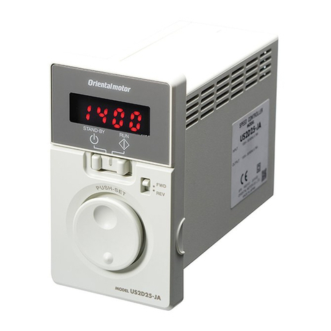
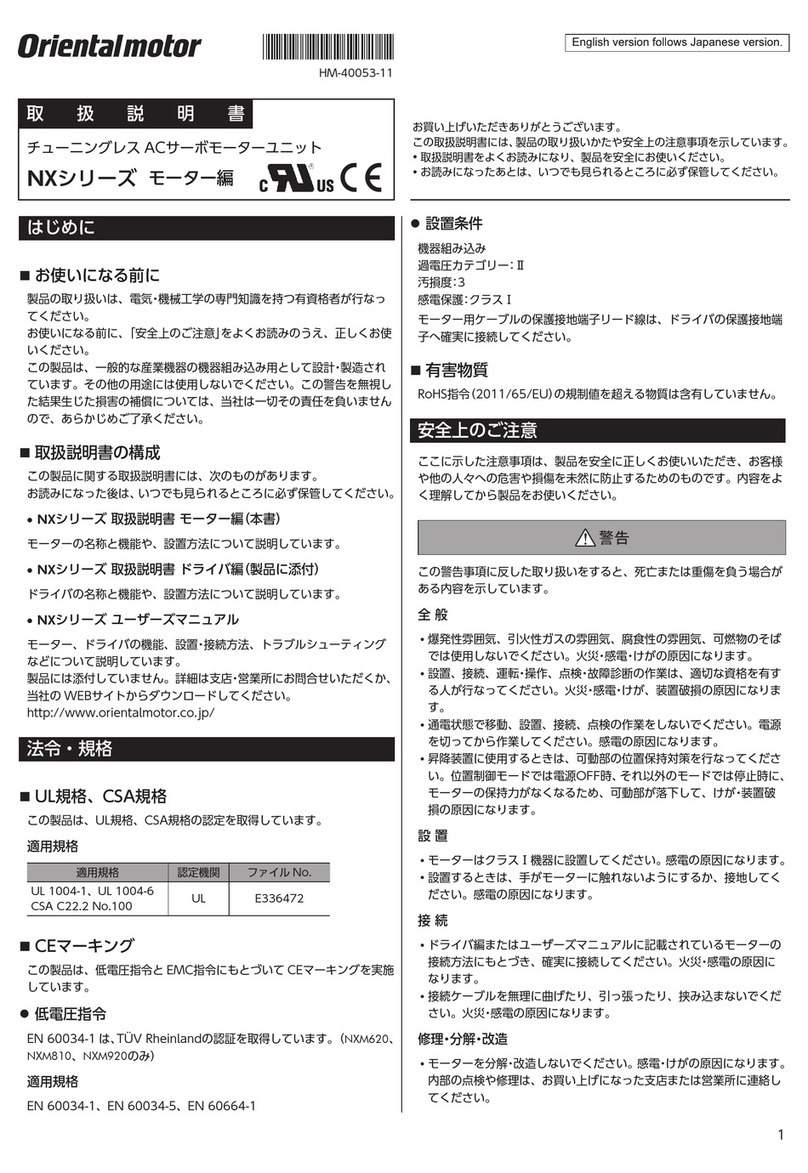
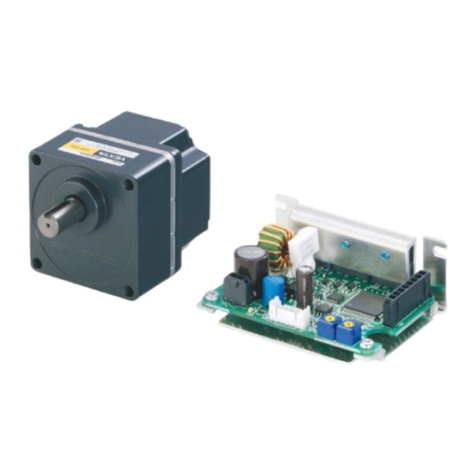
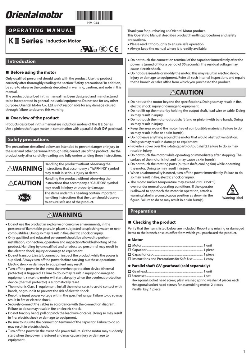
  9. Oriental motor SCM Series User manual

Oriental motor SCM Series User manual

1
Introduction
 Before using the motor
Only qualied personnel should work with the product. Use the product correctly
after thoroughly reading the section “Safety precautions.” In addition, be sure to
observe the contents described in warning, caution, and note in this manual.
The product described in this manual has been designed and manufactured to be
incorporated in general industrial equipment. Do not use for any other purpose.
Oriental Motor Co., Ltd. is not responsible for any damage caused through failure to
observe this warning.
 Operating manuals for the product
Operating manuals for this product are listed below.
 SCM Motor Connector type OPERATING MANUAL (this document)
This manual explains the motor functions and how to install the motor, among others.
 OPERATING MANUAL for each Series (supplied with the speed
controller)
This manual explains the function, installation and connection methods,
troubleshooting, and others for the speed controller.
Safety precautions
The precautions described below are intended to prevent danger or injury to the
user and other personnel through safe, correct use of the product.
Please read and understand these precautions thoroughly before using the product.
WARNING
Handling the product without observing the instructions
that accompany a "WARNING" symbol may result in serious
injury or death.
CAUTION
Handling the product without observing the instructions
that accompany a "CAUTION" symbol may result in injury or
property damage.
Note
The items under this heading contain important handling
instructions that the user should observe to ensure safe use
of the product.
Description of
graphic symbols
:Indicates "prohibited" actions that must not be performed.
:Indicates "compulsory" actions that must be performed.
WARNING
Do not use the product in explosive or corrosive environments, in the
presence of ammable gases, locations subjected to splashing water, or
near combustibles. Doing so may result in re, electric shock or injury.
Do not transport, install the product, perform connections or inspections
when the power is on. Always turn the power o before carrying out these
operations. Failure to do so may result in electric shock or equipment damage.
Do not use the electromagnetic brake of the motor as a safety brake.
Take safety measures other than the electromagnetic brake. Failure
to do so may result in injury or damage to equipment.
Use an electromagnetic brake motor in an application of vertical drive
such as elevating equipment. If a motor without an electromagnetic
brake is used, the moving part may drop. This may result in injury or
damage to equipment.
Do not machine or modify the connection cable. Doing so may result
in electric shock or re.
Do not forcibly bend, pull or pinch the cables. Doing so may result in
re and electric shock.
Do not touch the motor or speed controller when conducting
insulation resistance measurement or dielectric strength test.
Accidental contact may result in electric shock.
Do not disassemble or modify the motor and gearhead. This may cause
electric shock or injury.
Only qualied and educated personnel should be allowed to perform
installation, connection, operation and inspection/troubleshooting of the
product. Handling by unqualied and uneducated personnel may result
in re, electric shock, injury or equipment damage.
The motor is Class І equipment. When installing the motor, ground the
Protective Earth Terminal of the motor. Failure to do so may result in
electric shock.
Keep the input power voltage within the specied range. Failure to do so
may result in re or electric shock.
WARNING
Use a motor, gearhead and speed controller only in the specied
combination. An incorrect combination may cause in re, electric shock
or equipment damage.
Always turn o the power before performing maintenance/inspection.
Failure to do so may result in electric shock.
CAUTION
Do not use the motor, gearhead beyond its specications. Doing so
may result in electric shock, injury or damage to equipment.
Do not touch the motor, gearhead during operation or immediately
after stopping. The surface is hot and may cause a skin burn(s).
Keep the area around the motor free of combustible materials. Failure
to do so may result in re or a skin burn(s).
Do not leave anything around the motor that would obstruct
ventilation. Doing so may result in damage to equipment.
Do not carry the product by holding the motor, gearhead output
shaft or any of the cables. Doing so may result in injury.
Do not touch the motor output shaft (tip or pinion) with bare hands.
Doing so may result in injury.
When assembling the motor (pinion shaft) with the gearhead,
exercise caution not to pinch your ngers or other parts of your body
between the motor and gearhead. Injury may result.
When installing the motor, gearhead in the equipment, exercise
caution not to pinch your ngers or other parts of your body
between the equipment and motor or gearhead. Injury may result.
Do not touch the rotating part (output shaft) while operating the
motor. Doing so may result in injury.
When an abnormality is noted, turn o the power immediately. Failure to
do so may result in re, electrical shock or injury.
Securely install the motor, gearhead to their respective mounting
plates. Inappropriate installation may cause the motor, gearhead to
detach and fall, resulting in injury or equipment damage.
Provide a cover on the rotating part (output shaft). Failure to do so
may result in injury.
Securely install the load on the motor and gearhead output shaft.
Inappropriate installation may result in injury.
Be sure to ground the motor and speed controller to prevent them
from being damaged by static electricity. Failure to do so may result in
re or damage to equipment.
The motor surface temperature may exceed 70 °C (158 °F)
even under normal operating conditions. If the operator
is allowed to approach a running motor, attach a warning
label as shown in the gure in a conspicuous position.
Failure to do so may result in skin burn(s).
Warning
label
Precautions for use
This section covers limitations and requirements the user should consider when
using the product.
zBe sure to match the output power and power supply voltage
when combining a motor and speed controller
zConnecting the motor and speed controller
Use a connection cable (sold separately) when extending the wiring distance
between the motor and the speed controller.
zUse an electromagnetic brake motor in an application of vertical
drive such as elevating equipment
When the motor is used in an application of vertical drive such as elevating
equipment (lifting and lowering device), use an electromagnetic brake motor so that
the load can be held in position.
zCaution when using under low temperature environment
When an ambient temperature is low, since the load torque may increase by the
viscosity increment of the oil seal or grease, the motor starting may take a long time
or the motor rotation speed may fall. However, if the operation is continued for a
while, the oil seal or grease will be warmed up, and the motor can be driven at the
normal rotation speed.
HM-9421-2
OPERATING MANUAL Thank you for purchasing an Oriental Motor product.
This Operating Manual describes product handling procedures and safety
precautions.
Please read it thoroughly to ensure safe operation.
Always keep the manual where it is readily available.
AC Speed Control Motor
SCM Motor
2
zDo not forcibly stop the shaft rotation of gearhead by an
external force
Stopping in such a way may cause impact, leading to damage to the gearhead.
zRotation direction of the output shaft
The rotation direction of the gearhead output shaft with respect to the
motor output shaft is shown in the gure below.
Motor output shaft
(Including the round
shaft type)
Gearhead output shaft
SCM26
SCM315
SCM425
Gear ratio:
5 to 25, 150 to 360
Gear ratio:
2, 3, 30 to 120
SCM540
SCM560
Gear ratio:
5 to 18, 120 to 300
Gear ratio:
2, 3, 25 to 100
SCM590 Gear ratio:
5 to 15, 75 to 180
Gear ratio:
2, 3, 18 to 60
CW
CW CCW
CCW
CCW CW
Preparation
 Checking the product
Verify that the items listed below are included. Report any missing or damaged items
to the branch or sales oce from which you purchased the product.
 Motor .......................................................1 unit
The combination type comes with the motor and its dedicated gearhead pre-assembled.
 Mounting screw set ............................1 set (combination type only)
Hexagonal socket head screw, plain washer, spring washer 4 pieces each,
Parallel key 1 piece
 OPERATING MANUAL .........................1 copy (this document)
 Checking the model name
Check the model names of the motor and the gearhead
against the model name described on each nameplate.
Tell us the model name, product serial number, and
manufacturing date when you contact us.
For the information about the nameplate, check the
operating manual supplied with the speed controller.
Motor
Gearhead
Enter the code representing the power supply voltage in the box  within the
model name.
JA: Single-phase 100 V 50/60 Hz JC: Single-phase 200 V 50/60 Hz
UA: Single-phase 110/115 V 60 Hz EC: Single-phase 220/230 V 50/60 Hz
Enter the number representing the gear ratio of the gearhead in the box  within
the model name.
zCombination type • parallel shaft gearhead
Output
power Model Motor model Gearhead model Gear ratio
()
6 W SCM26-SCM26GV-2GVB
2 to 36015 W SCM315-SCM315GV-3GVB
25 W SCM425-SCM425GV-4GVB
40 W SCM540-SCM540GV-5GVB2 to 300
60 W SCM560-SCM560GVH-5GVHB
90 W SCM590-SCM590GVR-5GVRB2 to 180
zRound shaft type
Output
power Model Output
power Model Output
power Model
6 W SCM26A-25 W SCM425A-60 W SCM560A-
15 W SCM315A-40 W SCM540A-90 W SCM590A-
zElectromagnetic brake Combination type • parallel shaft gearhead
Output
power Model Motor model Gearhead model Gear ratio
()
6 W SCM26M-SCM26GV-M 2GVB
7.5 to 36015 W SCM315M-SCM315GV-M 3GVB
25 W SCM425M-SCM425GV-M 4GVB
40 W SCM540M-SCM540GV-M 5GVB7.5 to 300
60 W SCM560M-SCM560GVH-M 5GVHB
90 W SCM590M-SCM590GVR-M 5GVRB7.5 to 180
Installation
This section explains the installation method of a load in addition to the installation
location and installation method of the product.
 Installation location
Install the product in a well-ventilated location that provides easy access for inspection.
Indoors
Operating ambient temperature
Classication representing the power supply voltage
JA/JC: −10 to +50 °C (+14 to +122 °F) (non-freezing)
UA/EC: −10 to +40 °C (+14 to +104 °F) (non-freezing)
The lowest temperature is 0 °C (+32 °F) for gearheads of the gear ratio 2 and 3.
Operating ambient humidity 85% or less (non-condensing)
Area that is free from an explosive atmosphere or toxic gas (such as sulfuric gas) or
liquid
Area not exposed to direct sun
Area free of excessive amount dust, iron particles or the like
Area not subject to splashing water (storms, water droplets), oil (oil droplets) or
other liquids
Area free of excessive salt
Area not subject to continuous vibration or excessive shocks
Area free of excessive electromagnetic noise (from welders, power machinery, etc.)
Area free of radioactive materials, magnetic elds or vacuum
Altitude Up to 1000 m (3300 ft.) above sea level
Note On rare occasions, grease may ooze out from the gearhead. If there
is a concern over possible environmental damage resulting from the
leakage of grease, provide an oil tray or similar oil catching mechanism
in order not to cause a secondary damage. Grease leakage may lead to
problems in the customer's equipment or products.
 Installation method
Note Do not install the motor to the mounting hole diagonally or assemble
the motor forcibly. Doing so may cause damage to the motor.
zCombination type • parallel shaft gearhead
Secure the motor with mounting screw set (supplied) through the four mounting
holes provided. Do not leave a gap between the motor and mounting plate.
MotorGearhead
(L2)
L1
Motor
Hexagonal
socket head
screw
Gearhead
Mounting plate
Spring
washer
Washer Supplied
Mounting screw set (supplied)
Model Gear ratio
Hexagonal socket head
screw L2 [mm (in.)]
Tightening
torque
[N·m (lb-in)]
Screw size L1 [mm (in.)]
SCM26
2, 3, 30 to 120
M4
55 (2.17) 8 (0.31)
1.4 (12.3)5 to 25 50 (1.97) 7 (0.28)
150 to 360 60 (2.36) 8 (0.31)
SCM315
2, 3, 30 to 120
M6
65 (2.56) 12 (0.47)
5.0 (44)
5 to 25 60 (2.36) 12 (0.47)
150 to 360 70 (2.76) 12 (0.47)
SCM425
2, 3, 30 to 120 65 (2.56) 9 (0.35)
5 to 25 60 (2.36) 9 (0.35)
150 to 360 70 (2.76) 9 (0.35)
SCM540
SCM560
2, 3, 25 to 100
M8
85 (3.35) 16 (0.63)
12.0 (106)
5 to 18 70 (2.76) 14 (0.55)
120 to 300 90 (3.54) 15 (0.59)
SCM590
2, 3, 18 to 36 85 (3.35) 16 (0.63)
5 to 15 70 (2.76) 14 (0.55)
50 to 180 95 (3.74) 14 (0.55)
Removing/Installing the gearhead
See the following steps to replace the gearhead or to change the outlet position of
the lead wires and the position of the terminal box.
zRemoving the gearhead from the motor
Remove the hexagonal socket head screws (2 pieces)
assembling the motor and gearhead and detach the
motor from the gearhead.
Hexagonal socket
head screw
3
zInstalling the gearhead to the motor
Keep the pilot sections of the motor and
gearhead in parallel, and assemble the
gearhead with the motor while slowly
rotating it clockwise/counterclockwise.
At this time, note so that the pinion of the
motor output shaft does not hit the ange
or gears of the gearhead strongly. Pinion of
the motor
output shaft
Pilot section
Flange
Assemble the gearhead to the motor
in a condition where the motor output
shaft is in an upward direction.
Check no gaps remain between the motor and gearhead, and tighten them with
hexagonal socket head screws (2 pieces).
Model Screw size Tightening torque
[N·m (lb-in)]
SCM26
SCM315
SCM425
M2.6 0.4 (3.5)
SCM540
SCM560
SCM590
M3 0.6 (5.3)
Note
Do not forcibly assemble the motor and gearhead. Also, prevent metal
objects or foreign substances from entering in the gearhead. The
pinion of the motor output shaft or gear may be damaged, resulting
in noise or shorter service life.
Do not allow dust to attach to the pilot sections of the motor and
gearhead. Also, assemble the motor and gearhead carefully by not
pinching the O-ring at the motor pilot section. If the O-ring is crushed
or severed, grease may leak from the gearhead.
zRound shaft type
Secure the motor with hexagonal socket head screws (not supplied) through the four
mounting holes provided. Do not leave a gap between the motor and mounting plate.
Motor
Mounting plate
Model Screw size Tightening torque
SCM26 M4 1.8 N·m (15.9 lb-in)
[1.4 N·m (12.3 lb-in)]
SCM315
SCM425 M5 3.8 N·m (33 lb-in)
[3.0 N·m (26 lb-in)]
SCM540
SCM560
SCM590
M6 6.4 N·m (56 lb-in)
[5.0 N·m (44 lb-in)]
The number in parentheses [ ] indicates the value for
stainless steel hexagonal socket head screw.
zMotor with cooling fan
When installing a motor with cooling fan onto a device, leave 10 mm (0.39 in.) or more
behind the fan cover or open a ventilation hole so that the cooling inlet on the back
of the motor cover is not blocked.
 Installing a load
The gearhead shaft is provided with a key slot
for connecting the transmission parts. When
connecting the transmission parts, ensure that
the shaft and parts have a clearance t, and
always x the parallel key to the output shaft
with a screw to prevent the parts from rattling
or spinning.
Screw
Parallel key
Gearhead
output shaft
Note Do not apply excessive force onto the output shaft of the gearhead
using a hammer or other tools. Doing so may cause damage to the
output shaft or bearings.
zWhen using the output shaft end tapped hole of a gearhead
Use a tapped hole provided at the end of the output shaft as an auxiliary means for
preventing the transfer mechanism from disengaging.
SCM26, SCM315 type have no output shaft end tapped hole.
Model Output shaft end tapped hole Fixed screw
Screw
Spacer
Transmission
parts
SCM425 M5, Eective depth 10 mm (0.39 in.)
SCM540
SCM560
SCM590
M6, Eective depth 12 mm (0.47 in.)
 Permissible radial load and permissible axial load
The radial load and the axial load on the output shaft of the motor, gearhead must
be kept under the permissible values listed below.
Note Failure due to fatigue may occur when the motor (gearhead) bearings
and output shaft are subject to repeated loading by a radial or axial load
that is in excess of the permissible limit.
10 mm (0.39 in.)
20 mm (0.79 in.)
Distance from output shaft end
Axial load
Radial load
zCombination type • parallel shaft gearhead
Model Permissible radial load [N (lb.)]
Distance from tip of gearhead output shaft Permissible
axial load
[N (lb.)]
Gear ratio 10 mm (0.39 in.) 20 mm (0.79 in.)
SCM26
2100 (22) 150 (33) 15 (3.3)
3100 (22) 150 (33) 30 (6.7)
5 to 25 150 (33) 200 (45) 40 (9.0)
30 to 360 200 (45) 300 (67)
SCM315
2150 (33) 250 (56) 20 (4.5)
3150 (33) 250 (56) 40 (9.0)
5 to 25 200 (45) 300 (67) 80 (18.0)
30 to 360 300 (67) 400 (90)
SCM425
2300 (67) 350 (78) 25 (5.6)
3300 (67) 350 (78) 50 (11.2)
5 to 25 300 (67) 350 (78) 100 (22)
30 to 360 450 (101) 550 (123)
SCM540
SCM560
2250 (56) 350 (78) 100 (22)
3 to 9400 (90) 500 (112)
150 (33)
12.5 to 18 450 (101) 600 (135)
25 to 300 500 (112) 700 (157)
SCM590
2250 (56) 350 (78) 100 (22)
3 to 9400 (90) 500 (112)
150 (33)
12.5 to 18 450 (101) 600 (135)
25 to 180 500 (112) 700 (157)
zRound shaft type
Model
Permissible radial load [N (lb.)]
Distance from output shaft end of the motor Permissible axial load
[N (lb.)]
10 mm (0.39 in.) 20 mm (0.79 in.)
SCM26 50 (11.2) 110 (24)
Not to exceed one-half
the motor’s mass
SCM315 40 (9.0) 60 (13.5)
SCM425 90 (20) 140 (31)
SCM540 140 (31) 200 (45)
SCM560
SCM590 240 (54) 270 (60)
Minimize the axial load. If an axial load must be applied, do not let it exceed one-
half the motor’s mass.
Grounding
Ground close to the motor at a shortest distance using
the Protective Earth Terminal of the motor.
Grounding
 Ground terminal
Use a crimp terminal described below for grounding.
Applicable crimp terminal:
Round crimp terminal with insulation cover
Thread size of terminal: M4
Tightening torque:
1.0 to 1.3 N·m (8.8 to 11.5 lb-in)
Applicable lead wire:
AWG18 (0.75 mm2) or thicker
Ø4.1 (0.16) or more
[ Unit: mm (in.) ]
4.8 (0.19) or less
9.5 (0.37)
or less
Note Be sure to use the screw for grounding attached on the product.
4
Unauthorized reproduction or copying of all or part of this manual is prohibited.
Oriental Motor shall not be liable whatsoever for any problems relating to
industrial property rights arising from use of any information, circuit, equipment
or device provided or referenced in this manual.
Characteristics, specications and dimensions are subject to change without
notice.
While we make every eort to oer accurate information in the manual, we
welcome your input. Should you nd unclear descriptions, errors or omissions,
please contact the nearest oce.
 is a registered trademark or trademark of Oriental Motor Co., Ltd.,
in Japan and other countries.
© Copyright ORIENTAL MOTOR CO., LTD. 2018
Published in June 2018
Technical Support Tel:(800)468-3982
8:30 A.M. to 5:00 P.M., P.S.T. (M-F)
7:30 A.M. to 5:00 P.M., C.S.T. (M-F)
www.orientalmotor.com
Schiessstraße 44, 40549 Düsseldorf, Germany
Technical Support Tel:00 800/22 55 66 22
www.orientalmotor.de
Tel:01256-347090
www.oriental-motor.co.uk
Tel:01 47 86 97 50
www.orientalmotor.fr
Tel:02-93906346
www.orientalmotor.it
Tel:+55-11-3266-6018
www.orientalmotor.com.br
• Please contact your nearest Oriental Motor oce for further information.
4-8-1Higashiueno,Taito-ku,Tokyo 110-8536
Japan
Tel:03-6744-0361
www.orientalmotor.co.jp
Tel:0800-060708
www.orientalmotor.com.tw
Singapore
Tel:1800-8420280
www.orientalmotor.com.sg
Tel:1800-806161
www.orientalmotor.com.my
Korea
Tel:080-777-2042
www.inaom.co.kr
Tel:1800-888-881
www.orientalmotor.co.th
Tel:400-820-6516
www.orientalmotor.com.cn
Tel:+91-80-41125586
www.orientalmotor.co.in
Hong Kong Branch
Tel:+852-2427-9800
Time rating
Continuous operation is possible (continuous rating).
Maintenance · inspection
 Inspection
It is recommended that periodic inspections would be conducted for the items
listed below after each operation of the motor. If an abnormal condition is noted,
discontinue any use and contact your nearest Oriental Motor sales oce.
Note Do not conduct the insulation resistance measurement or dielectric
strength test with the motor and speed controller connected. Doing so
may cause damage to the product.
zInspection item
Check if any of the mounting screws of the motor and gearhead are loose.
Check if the bearing part (ball bearings) of the motor generates unusual noises.
Check if the bearing part (ball bearings) or gear meshing part of the gearhead
generates unusual noises.
Check if the output shaft of the motor and gearhead and a load shaft are out of
alignment.
Check if a damage or stress is applied on the cable or the connection part between
the cable and speed controller is loose.
 Warranty
Check on the Oriental Motor Website for the product warranty.
 Disposal
Dispose the product correctly in accordance with laws and regulations, or
instructions of local governments.
Specications
Check on the Oriental Motor Website for the product specications.
General specications
Operation
environment
Ambient
temperature
Classication representing the power supply voltage
JA/JC: −10 to +50 °C (+14 to +122 °F) (non-freezing)
UA/EC: −10 to +40 °C (+14 to +104 °F) (non-freezing)
The lowest temperature is 0 °C (+32 °F) for gearheads
of the gear ratio 2 and 3.
Ambient
Humidity 85% or less (non-condensing)
Altitude Up to 1000 m (3300 ft.) above sea level
Surrounding
atmosphere
No corrosive gas, dust, water or oil.
Cannot be used in radioactive materials,
magnetic eld, vacuum or other special environment.
Vibration
Not subject to continuous vibrations or excessive impact.
In conformance with JIS C 60068-2-6 "Sinewave
vibration test method"
Frequency range: 10 to 55 Hz
Pulsating amplitude: 0.15 mm (0.006 in.)
Sweep direction: 3 directions (X, Y, Z)
Number of sweeps: 20 times
Storage
environment
Shipping
environment
Ambient
temperature −25 to +70 °C [−13 to +158 °F] (non-freezing)
Ambient
Humidity 85% or less (non-condensing)
Altitude Up to 3000 m (10000 ft.) above sea level
Surrounding
atmosphere
No corrosive gas, dust, water or oil.
Cannot be used in radioactive materials,
magnetic eld, vacuum or other special environment.
Overheat Protection Device
SCM26: Impedance protected
Other motors: Built-in thermal protector
(automatic return type)
Open (motor standstill) ...........130±5 °C (266±9 °F)
Close (resuming operation) .... 85±20 °C (185±36 °F)
Degree of protection IP20
Regulations and standards
 UL Standards, CSA Standards, CCC System
This product is recognized by UL under the UL and CSA Standards, and also certied
by CQC under the China Compulsory Certication (CCC) system.
The motor model name represents the model that conforms to the standards.
Applicable standards Certication Body / File No.
UL 1004-1, UL 1004-2, UL 1004-3
CSA C22.2 No.100, CSA C22.2 No.77 UL/UL File No.E64197, E64199
GB/T 12350 CQC
Thermal Class: 130 (B)
 CE Marking
This product is axed the CE Marking under the Low Voltage Directive.
zLow Voltage Directive
Applicable standards
EN 60034-1, EN 60034-5, EN 60664-1
Momentary excess torque based on EN 60034-1
Model Momentary
excess torque Momentary excess torque represents a
maximum torque that can maintain the
operation for 15 seconds without stalling
or abrupt speed change even if the torque
is increased gently while operating at rated
voltage and rated frequency.
SCM315, SCM560 120% of the
rated torque
SCM26, SCM425
SCM540, SCM590
130% of the
rated torque
Installation conditions (For EN standard)
For incorporating in equipment
Overvoltage category: ІІ
Pollution degree: 2
Protection against electric shock: Class І
 Motor temperature rise tests
Temperature rise tests stipulated in the standards are conducted in a condition
where a motor is mounted on a heat radiation plate instead of attaching a gearhead.
The size and material for the heat radiation plates are as follows.
[mm (in.)]
Model Size Thickness Material
SCM26 115×115 (4.53×4.53)
5 (0.20) Aluminum alloy
SCM315 125×125 (4.92×4.92)
SCM425 135×135 (5.31×5.31)
SCM540 165×165 (6.50×6.50)
SCM560, SCM590 200×200 (7.87×7.87)
 RoHS Directive
The products do not contain the substances exceeding the restriction values of RoHS
Directive (2011/65/EU).

This manual suits for next models

18

Other Oriental motor Engine manuals

Oriental motor BH Series User manual

Oriental motor

Oriental motor BH Series User manual

Oriental motor 2LSB10 User manual

Oriental motor

Oriental motor 2LSB10 User manual

Oriental motor BMU Series User manual

Oriental motor

Oriental motor BMU Series User manual

Oriental motor PKP242D23A2 User manual

Oriental motor

Oriental motor PKP242D23A2 User manual

Oriental motor BLM230- B Series User manual

Oriental motor

Oriental motor BLM230- B Series User manual

Oriental motor BLE2 Series User manual

Oriental motor

Oriental motor BLE2 Series User manual

Oriental motor CRK Series User manual

Oriental motor

Oriental motor CRK Series User manual

Oriental motor BLV Series User manual

Oriental motor

Oriental motor BLV Series User manual

Oriental motor 0GN KA Series User manual

Oriental motor

Oriental motor 0GN KA Series User manual

Oriental motor K Series User manual

Oriental motor

Oriental motor K Series User manual

Oriental motor RKII Series User manual

Oriental motor

Oriental motor RKII Series User manual

Oriental motor PK Series User manual

Oriental motor

Oriental motor PK Series User manual

Oriental motor CSK Series User manual

Oriental motor

Oriental motor CSK Series User manual

Oriental motor World K Series User manual

Oriental motor

Oriental motor World K Series User manual

Oriental motor BXM230 User manual

Oriental motor

Oriental motor BXM230 User manual

Oriental motor 2TK3GN-AW2J User manual

Oriental motor

Oriental motor 2TK3GN-AW2J User manual

Oriental motor CFK Series User manual

Oriental motor

Oriental motor CFK Series User manual

Oriental motor BLM5120HPM User manual

Oriental motor

Oriental motor BLM5120HPM User manual

Oriental motor BLM Series User manual

Oriental motor

Oriental motor BLM Series User manual

Oriental motor NX Series User manual

Oriental motor

Oriental motor NX Series User manual

Oriental motor PK Series User manual

Oriental motor

Oriental motor PK Series User manual

Oriental motor BMU Series User manual

Oriental motor

Oriental motor BMU Series User manual

Oriental motor US Series User manual

Oriental motor

Oriental motor US Series User manual

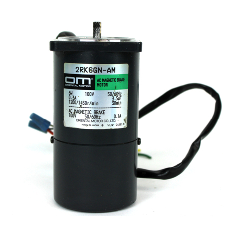
Oriental motor 2RK6GN-AM User manual

Oriental motor

Oriental motor 2RK6GN-AM User manual

Popular Engine manuals by other brands

Roto 85 FS operating instructions

Roto

Roto 85 FS operating instructions

Perkins 1104D NH1 Systems operation testing and adjusting

Perkins

Perkins 1104D NH1 Systems operation testing and adjusting

TILLOTSON HL Series Service manual

TILLOTSON

TILLOTSON HL Series Service manual

Cobalt Classic CB Omega-A-0314 owner's manual

Cobalt Classic

Cobalt Classic CB Omega-A-0314 owner's manual

Briggs & Stratton 194700 Series owner's manual

Briggs & Stratton

Briggs & Stratton 194700 Series owner's manual

nekos MR28-B instruction manual

nekos

nekos MR28-B instruction manual

Beta Marine Beta 14 installation guide

Beta Marine

Beta Marine Beta 14 installation guide

FAAC T-MODE TM 45 E manual

FAAC

FAAC T-MODE TM 45 E manual

MOTO GUZZI Engine V1100 Workshop manual

MOTO GUZZI

MOTO GUZZI Engine V1100 Workshop manual

Lenze M Series manual

Lenze

Lenze M Series manual

PEUGEOT TSDI Workshop manual

PEUGEOT

PEUGEOT TSDI Workshop manual

Jets Munt M-XBL Series instruction manual

Jets Munt

Jets Munt M-XBL Series instruction manual

Siemens Simotics SD 1LE7 operating instructions

Siemens

Siemens Simotics SD 1LE7 operating instructions

Absima Revenge CTM Series quick start guide

Absima

Absima Revenge CTM Series quick start guide

Eurotherm AC M2n Series product manual

Eurotherm

Eurotherm AC M2n Series product manual

Craftsman 143.625082 owner's manual

Craftsman

Craftsman 143.625082 owner's manual

Continental Refrigerator IOF-240-B Maintenance manual

Continental Refrigerator

Continental Refrigerator IOF-240-B Maintenance manual

Coulisse MOTION CM-08 manual

Coulisse

Coulisse MOTION CM-08 manual

manuals.online logo
manuals.online logoBrands
  • About & Mission
  • Contact us
  • Privacy Policy
  • Terms and Conditions

Copyright 2025 Manuals.Online. All Rights Reserved.