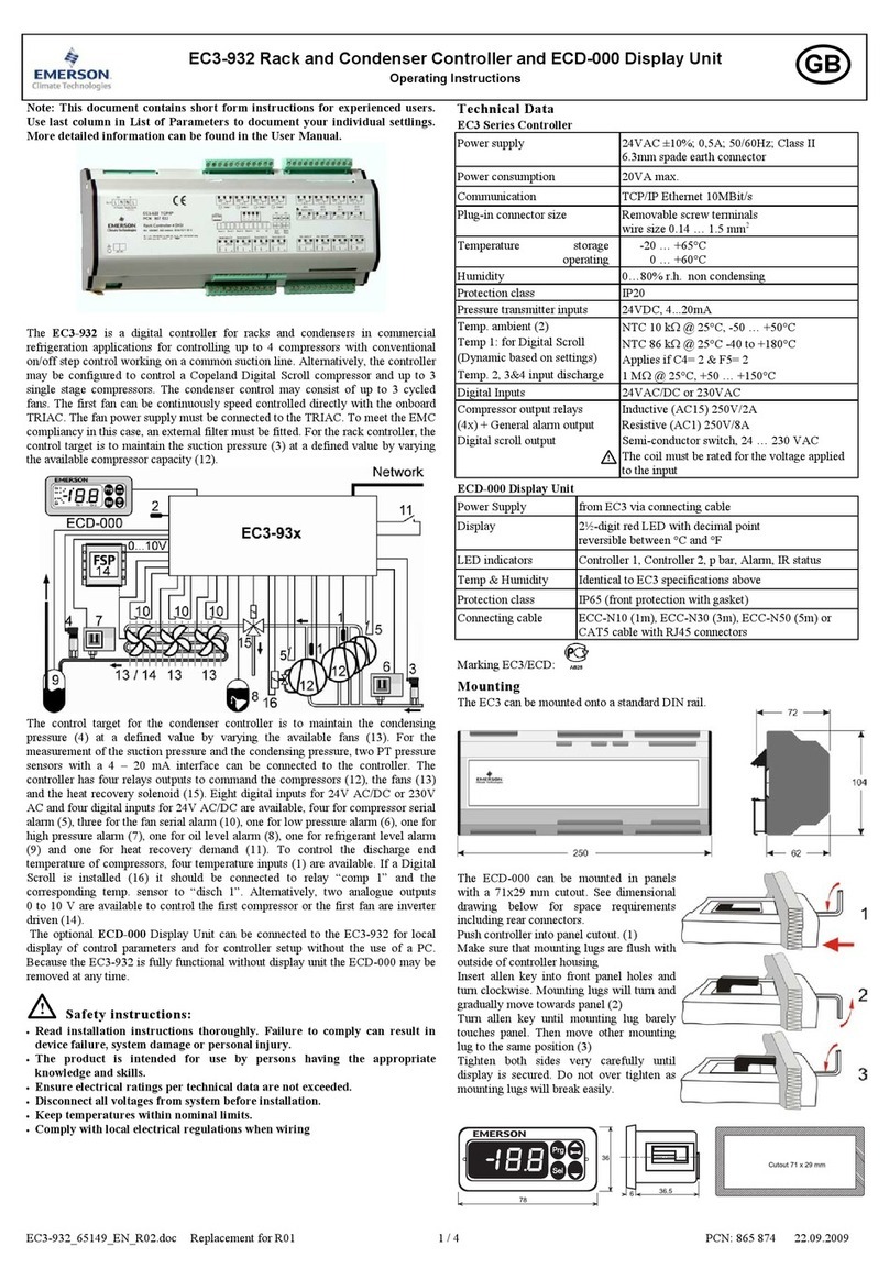
Manaras Opera M-85 Use and care manual

Note:
Read this manual carefully before
replacing the existing board and place this
installation manual in an accessible place near
the operator. For future reference record:
Model #
Date
Wiring Diagram #
Door No. #
R
R
e
ep
pl
la
ac
ce
em
me
en
nt
t
a
an
nd
d
I
In
ns
st
ta
al
ll
la
at
ti
io
on
n
I
In
ns
st
tr
ru
uc
ct
ti
io
on
ns
s
M
MA
A
-
-1
10
00
0
L
Lo
og
gi
ic
c
C
Co
on
nt
tr
ro
ol
ll
le
er
r
R
R
e
ep
pl
la
ac
ce
em
me
en
nt
t
B
Bo
oa
ar
rd
d
M
M-
-8
85
5
&
&
M
MH
HD
D-
-8
85
5
®
TM

2
Important changeover instructions
Please read the following instructions carefully before changing the controller over to another.
The following instructions apply to all the gate operators built with MA-100 logic controller
model: M-85 & MHD-85 – single-phase 115/120V. We have tried every effort to minimize the
time required to change over these boards.
NOTICE
Step by step changeover instructions
1. Disconnect all power to gate operator.
2. Remove the four bolts holding the MA-100 controller.
3. Install the Manaras-Opera logic controller. The controller is supplied with a pre-wired
transformer and shall be installed in the control box, depending upon the space available.
4. Fix the transformer. Locate a free space in the control box and secure the transformer supplied
with the new controller.
5. Remove the two 14-pole plug connector from the socket. One 14-poles connector is numbered
1 to 14 and the second one is numbered as 15 to 28.
6. Once the MA-100 controller is removed, replace it with Manaras-Opera Controller. Since the
new controller does not have any socket connector like MA-100, but instead is provided with
regular terminal strip numbered accordingly.
7. Remove all the wires from the 14-poles connector numbered 1 to 14. Remove 10-k ohms
resistor and two jumper wires between 1 to 9 and 1 to 10 permanently. Once all the wires are
removed, connect back all the wires to the corresponding numbers provided on the terminal
strip on Manaras-Opera controller. Make sure all the wires are connected to the respective
numbers.
8. Remove all existing wires on the second 14-poles connector, which are numbered as 15 to 28.
Once the wires are removed, connect back the wires from terminal # 16, 20, 21, 24 & 25 to
respective numbers on the new terminal strip provided on Manaras-Opera controller. If any
warning Lights were connected on 22 and 23 they should be removed.
9. Do not disconnect any external devices like push button station, safety edge, exit loop, safety
loop, radio control etc. We tried every aspect not to disturb these, but if you wish to use some
of the added features to this new controller refer to the instruction manual provided.
10. Refer to the electrical drawing and instruction manual for more details
WARNING
Neglecting to follow these instructions will result in complete damage to the controller. If you
are not confident, please consult Manaras-Opera for assistance.

3

4
Program and Program settings
Programming ability and door control at electrical box are provided by Open/Close/Stop buttons and Select
Switch located on the ECB.
• Programs
• Program setting
Door should be in fully closed position while setting of these following programs.
PROGRAMS FUNCTIONS AND DESCRIPTIONS
RUN TIMER The Run Timer stops automatically the operator after an adjustable time delay either
travelling upwards or downwards. The Run Timer is designed to protect the door and
the operator by preventing the motor over running much longer than the normal time.
MID-STOP Mid-Stop function will, when active, move the door from the down position to a
predetermined Mid-stop position when the open button or Open/Close device is
activated. Once at Mid-Stop, subsequent Open/close commands will close the door. To
move the door to full open position, the open button must be pressed again.
TIMER TO CLOSE Timer to Close is a function that, when active, will close the door after an adjustable
time delay once the door has reached its fully open and mid-stop position. The timer to
close function works only in T and TS modes.
TIMER TO CLOSE (from
fully open position only) Option used in conjunction with MID STOP function. When activated, Timer to Close is
active from the fully open position only and not from the mid-stop position.
ADVANCE CLOSED
TIME
“Advance close limit switch” is not needed with this feature. Advance close time will
disable the reversing device once the close limit switch is activated and will stop the
door after 200 milliseconds before it reaches the fully closed position.
Note: Door distance traveled within these 200 milliseconds may vary depending on the
door speed.
PROGRAM SETTING
PROGRAMS ACTIVATE DEACTIVATE SELECT
SWITCH
RUN TIMER
• Check if close limit switch is activated.
• Set select switch on D.
• Press “Open” button to add 10 sec to the
total time needed to open the door.
• Set the select switch on run mode (0, 1, 2, 3,
4 or 5).
• Set select switch on D.
• Press “Stop” button.
• Set the select switch on run mode (0, 1, 2, 3,
4 or 5).
MID-STOP
• Check if the close limit is activated.
• Set select switch on “C”.
• Press “Open” button then press “Stop”
button on desired Mid-Stop position.
• Set the select switch back on run mode (0,
1, 4 or 5).
• Set select switch on “C”.
• Press “Stop”, “Close” and “Open” buttons
consecutively.
• Set the select switch back on run mode (0,
1, 4 or 5).
TIMER TO
CLOSE
• Set select switch on “B”.
• Press “Open” button to add 15 sec or
“Close” button to add 1 sec each time (max.
4 minutes & 15 seconds).
• Set the select switch on T or TS mode.
• Set select switch on “B”.
• Press “Stop” button the timer to close is
reset to 0 sec but still activated.
• To defeat the timer to close completely set
the switch on desired position (0, 1, 2 or 3).
TIMER TO
CLOSE
(from fully open
position only)
• Set select switch on ”6”.
• First press the “Close” button and then the
“Stop”.
• Set the select switch on T or TS mode.
• Set select switch on “6”.
• Press “Close” button.
• Set the select switch on T or TS mode.
*Now the Timer to Close works from fully open
and Mid-Stop positions.
Controlling Timer to Close from floor level (using wall buttons)
While door is in closed position, by pressing “Stop” 3 times and
“Close” 3 times consecutively on the push button station, the timer
to close is deactivated (timer to close is suspended).
Timer to close is re-activated (timer to close is back to
normal function) simply when door is closed either from fully
open or from mid-stop positions.
8
9
D
B
A
C
E
F
0
7
2
6
5
3
4
1
D
C
B
A
9
8
F
E
0
3
6
5
7
4
2
1
D
A
B
C
9
8
F
E
0
4
6
5
7
2
1
3
0
F
D
B
C
A
9
8
E
1
6
7
5
2
4
3

5
MODE SETTING
Wiring
Type Wiring Type & Functions Select
Switch
C2
(factory
preset)
Set select switch on 0
Momentary contact to open and stop, constant pressure to close with 3 buttons
station. Activation of safety devices will reverse the door during closing. Auxiliary
devices function as an Open control and to reverse door during closing.
B2
Set the select switch on 1.
Momentary contact to Open/Close and Stop with 3 buttons station. Activation of
safety devices will reverse the door during closing. Auxiliary devices function as
Open/Close control and reverse the door during closing.
D1 Set the select switch on 2.
Constant pressure to Open and constant pressure to Close. Activation of
safety devices will stop the door during closing.
E2
Set the select switch on 3
Momentary contact to open and constant pressure to Close. Release of Close
button activates the door upwards. Activation of safety devices will reverse door
motion to fully open position.
T
Set the select switch on 4.
Momentary contact to Open / Close and Stop. Timer to Close if programmed,
safety devices reverse upon but will disable Timer to Close. Timer to close will
also be disabled if there is a power outage, a chain hoist is engaged or the stop
is pressed before elapsed time. The timer resumes its normal operation, once
the close cycle is completed.
TS
Set the select switch on 5.
Momentary contact to Open / Close and Stop. Timer to Close if
programmed, safety devices reverse upon activation and will refresh Timer
to Close. Timer to close also gets refreshed, if there is a power outage, a
chain hoist is engaged or a stop button is pressed before elapsed time.
IMPORTANT NOTES:
• STOP JUMPER
• While testing the operator or adjusting the cams using the O/C/S buttons available on the
Electronic Control Board, a jumper should be placed between the #8 & #9. Once the tests or
adjustments completed the jumper should removed before connecting the wall 3-push buttons
station. Failure to remove the stop jumper, the STOP BUTTON WILL NOT RESPOND.
• A stop jumper should be installed between #8 & #9 when using a Key switch, a single button
Radio control or a 2-buttons station (Open/Close). IN THESE CONDITIONS NO STOP
COMMAND IS AVAILABLE TO STOP THE DOOR DURING THE TRAVELLING.
WARNING
MOTORIZED DOORS CAN CAUSE SEVERE INJURY OR DEATH. MANARAS STRONGLY
RECOMMENDS THE USE OF ENTRAPMENT PROTECTION SYSTEMS, ESPECIALLY IN THE CASES
OF MOMENTARY CONTACT TO CLOSE (B2 WIRING) AND TIMER TO CLOSE (T & TS).

6
NOTES

7
NOTES

8
BOOK084 REV 2- 2009/11/16
Reg. T.M. of 9141-0720 Québec Inc.
OPERA
This manual suits for next models
1
Table of contents
