Gas hot-air heater MONZUN |instalation, operation instractions and maintenance manual
4 |
EN GENERAL
This manual is an integral part of the product and must be given to the end user together with the equipment.
a) Gas hot-air heaters MONZUN may only be used by a person
who has been instructed in the normal use of the appliance
and who understands the possible dangers.
b) Persons with reduced physical, sensory or mental abilities or
a lack of experience and knowledge may only use the heater
under the supervision of a person trained according to point a).
c) Children cannot use or play with the MONZUN heater.
MONZUN air heaters meet the ecodesign requirements of ErP
2021 according to Commission Regulation (EU) 2016/2281.
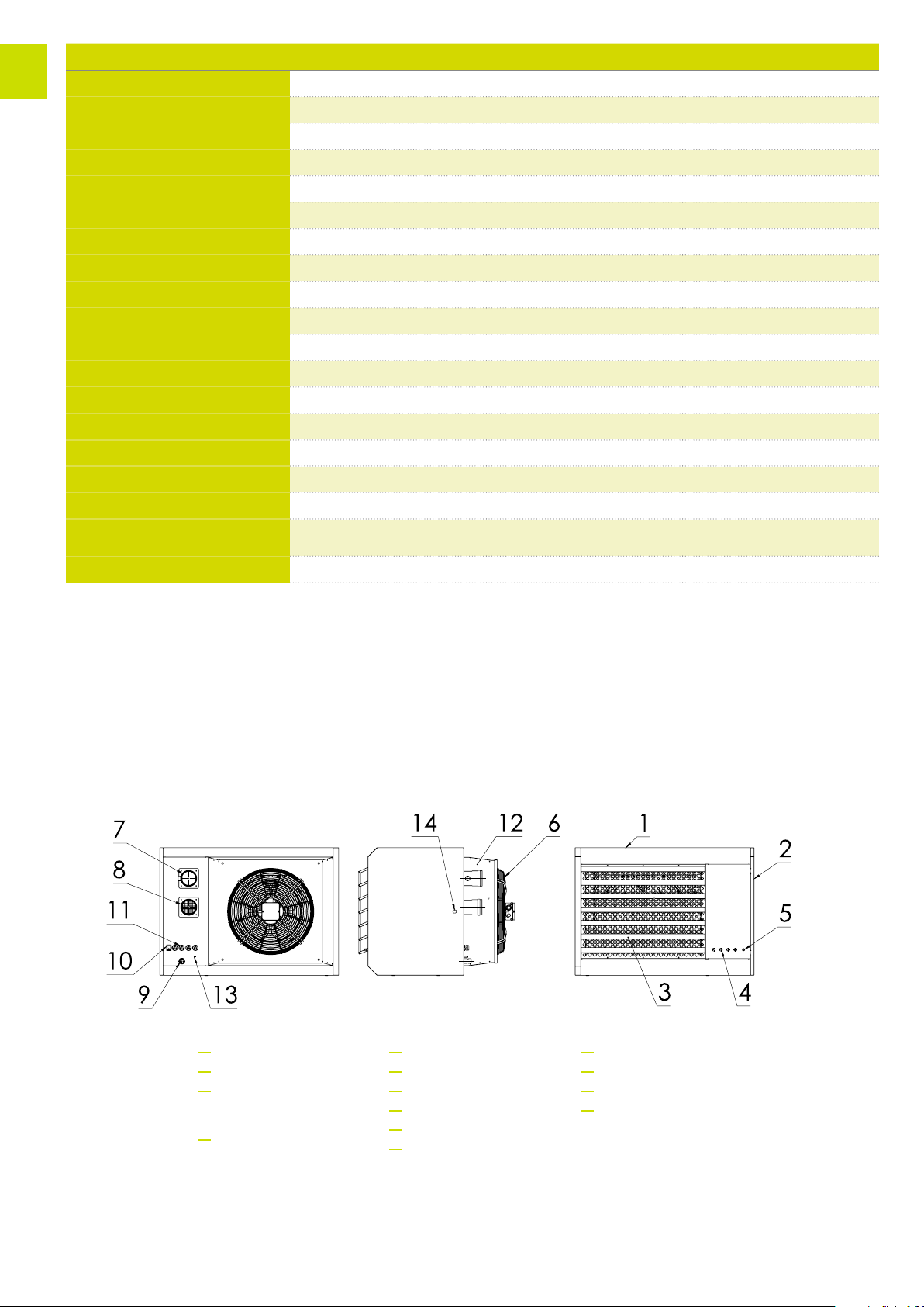
Description of heaters MONZUN
Hot air gas heaters MONZUN are designed for ventilation and ecolog-
ical heating of rooms and halls by heated air. Available versions are
in a power range from 15 kW to 60 kW with an airow from 2,500 to
8,000m/h in size: 15, 20, 30, 40, 50 and 60. In terms of gas extraction
equipment, it is an open or closed appliance with forced exhaust ue
gas.
Appliance categories - II2E3B/P, II2ELL3B/P, design B23, C13, C33, C63
Degree of electrical protection is IP40
Emission value NOxto 70 mg/kWh acc. to commission regulation (EU)
2016/2281 (Ecodesign 2021)
Emission class – NOx5
A common operating fuel for MONZUN units is:
• natural gas – ZP (G20/G25)
• propane-butane – PB (G30/G31)
• propane – P (G31)
The MONZUN heaters are in the standard version intended for instal-
lation in weather-protected environments of class 3K3 according to
EN 60721-3-3 with temperature range from 0° to +35 °C, for spac-
es without explosion hazard according to EN 1127-1. The air pass-
ing through the unit and the combustion air must not contain solid,
brous, sticky or aggressive particles. They cannot be installed in
rooms where there is a risk of re or explosion.
The control of the power output of the MONZUN heaters is continu-
ous from minimum power to rated/maximum power. The heated air
ow is forced by an axial fan.
Due to the high eciency it is necessary to install a condensate drain
from the chimney, unless it is otherwise addressed in special cases.
Description of function
The heater operation is controlled by the control automatics.
After the heater is switched on, the burner fan starts to ventilate and
the exchanger is ventilated with fresh air for 30 s.
After the venting time, starting speed of the burner fan is set by the
control automatics, the burner electrical ignition is triggered and the
electromagnetic gas valve is opened. After the burner is ignited, the
speed of the burner fan is adjusted to the operating speed according
to the required power.
When the heater exchanger is heated to the set temperature, the fan
operating thermostat triggers the axial air fan and the heater starts
to blow heated air.
When the heater is switched o, the control unit automatically closes
the electromagnetic gas valve, the speed of the burner fan is adjust-
ed to the ventilating speed and the exchanger is ventilated with fresh
air. The axial air fan keeps running and ensures that the exchanger
cools down below the set temperature.
The function of the burner fan is monitored by the control automat-
ics with the help of the fan motor speed sensor.
The temperature of the exchanger is monitored by thermostats:
• Operating thermostat of ventilator (switches the axial fan ON and
OFF according to set temperature)
• Burner operating thermostat (checks the correct temperature of
the heat exchanger, if the set temperature is exceeded, its shuts
down the burner operation)
• Emergency thermostat (checks the maximum allowable tempe-
rature of the heat exchanger and when this limit temperature is
reached, shuts down the gas burner and activates the warning
light. Operator intervention is required to unblock the emergency
thermostat. Operator should check the heater and unblock the
emergency thermostat.)
The control of the output power of the hot-air heater is carried out by
the control signal 0–10 V (DC ±) or by Modbus. If the control signal is
not connected, after the heater is switched on by the service switch,
the heater switches to minimum power output.