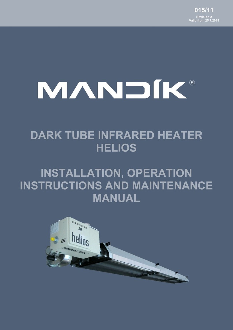
Mandik HELIOS Instructions for use

®
Installation,
operation instructions
and maintenance manual
Dark tube infrared heater
HELIOS
015/11
Revision 8 | Valid from 1. 1. 2022

Dark tube infrared heater HELIOS | Installation, operation instructions and maintenance manual.
2 |TP 015/11
CONTENT
I. GENERAL . . . . . . . . . . . . . . . . . . . . . . . . . . . . . . . . . . . . . . . . . . . . . . . . . . . . . . . . . . . . . . . . . . . . . . . . . . . . . . . . . . . . . . .4
Infrared heater description. . . . . . . . . . . . . . . . . . . . . . . . . . . . . . . . . . . . . . . . . . . . . . . . . . . . . . . . . . . . . . . . . . . . . . . . . . . . .4
Versions . . . . . . . . . . . . . . . . . . . . . . . . . . . . . . . . . . . . . . . . . . . . . . . . . . . . . . . . . . . . . . . . . . . . . . . . . . . . . . . . . . . . . . . . . . 4
Dimensions and weights . . . . . . . . . . . . . . . . . . . . . . . . . . . . . . . . . . . . . . . . . . . . . . . . . . . . . . . . . . . . . . . . . . . . . . . . . . . . . . 5
Description of function . . . . . . . . . . . . . . . . . . . . . . . . . . . . . . . . . . . . . . . . . . . . . . . . . . . . . . . . . . . . . . . . . . . . . . . . . . . . . . . 6
Ordering key . . . . . . . . . . . . . . . . . . . . . . . . . . . . . . . . . . . . . . . . . . . . . . . . . . . . . . . . . . . . . . . . . . . . . . . . . . . . . . . . . . . . . . . 6
Material, surface treatment . . . . . . . . . . . . . . . . . . . . . . . . . . . . . . . . . . . . . . . . . . . . . . . . . . . . . . . . . . . . . . . . . . . . . . . . . . . . 7
Data label . . . . . . . . . . . . . . . . . . . . . . . . . . . . . . . . . . . . . . . . . . . . . . . . . . . . . . . . . . . . . . . . . . . . . . . . . . . . . . . . . . . . . . . . . 7
Control . . . . . . . . . . . . . . . . . . . . . . . . . . . . . . . . . . . . . . . . . . . . . . . . . . . . . . . . . . . . . . . . . . . . . . . . . . . . . . . . . . . . . . . . . . .7
Logistic data . . . . . . . . . . . . . . . . . . . . . . . . . . . . . . . . . . . . . . . . . . . . . . . . . . . . . . . . . . . . . . . . . . . . . . . . . . . . . . . . . . . . . . . 7
II. INSTALLATION MANUAL . . . . . . . . . . . . . . . . . . . . . . . . . . . . . . . . . . . . . . . . . . . . . . . . . . . . . . . . . . . . . . . . . . . . . . . . .8
Installation conditions . . . . . . . . . . . . . . . . . . . . . . . . . . . . . . . . . . . . . . . . . . . . . . . . . . . . . . . . . . . . . . . . . . . . . . . . . . . . . . . . 8
Suspension methods . . . . . . . . . . . . . . . . . . . . . . . . . . . . . . . . . . . . . . . . . . . . . . . . . . . . . . . . . . . . . . . . . . . . . . . . . . . . . . . . . 8
Mounting components of infrared heater HELIOS . . . . . . . . . . . . . . . . . . . . . . . . . . . . . . . . . . . . . . . . . . . . . . . . . . . . . . . . . . . . 9
Instructions for assembling the body of the infrared heater . . . . . . . . . . . . . . . . . . . . . . . . . . . . . . . . . . . . . . . . . . . . . . . . . . . . 13
Placement of the burner box . . . . . . . . . . . . . . . . . . . . . . . . . . . . . . . . . . . . . . . . . . . . . . . . . . . . . . . . . . . . . . . . . . . . . . . . . . 17
Installation of the exhaust box . . . . . . . . . . . . . . . . . . . . . . . . . . . . . . . . . . . . . . . . . . . . . . . . . . . . . . . . . . . . . . . . . . . . . . . . . 18
Flue exhaust – connection principles . . . . . . . . . . . . . . . . . . . . . . . . . . . . . . . . . . . . . . . . . . . . . . . . . . . . . . . . . . . . . . . . . . . . 18
Gas connection installation . . . . . . . . . . . . . . . . . . . . . . . . . . . . . . . . . . . . . . . . . . . . . . . . . . . . . . . . . . . . . . . . . . . . . . . . . . . 20
Electrical installation . . . . . . . . . . . . . . . . . . . . . . . . . . . . . . . . . . . . . . . . . . . . . . . . . . . . . . . . . . . . . . . . . . . . . . . . . . . . . . . . 20
III. COMMISSIONING AND SERVICE . . . . . . . . . . . . . . . . . . . . . . . . . . . . . . . . . . . . . . . . . . . . . . . . . . . . . . . . . . . . . . . . .21
Commissioning conditions. . . . . . . . . . . . . . . . . . . . . . . . . . . . . . . . . . . . . . . . . . . . . . . . . . . . . . . . . . . . . . . . . . . . . . . . . . . .21
Adjustment procedure of single-stage and two-stage heaters . . . . . . . . . . . . . . . . . . . . . . . . . . . . . . . . . . . . . . . . . . . . . . . . . . 21
Adjustment procedure of modulated heaters . . . . . . . . . . . . . . . . . . . . . . . . . . . . . . . . . . . . . . . . . . . . . . . . . . . . . . . . . . . . . . 22
Maintenance . . . . . . . . . . . . . . . . . . . . . . . . . . . . . . . . . . . . . . . . . . . . . . . . . . . . . . . . . . . . . . . . . . . . . . . . . . . . . . . . . . . . . .29
Failure of infrared heaters HELIOS and their removal . . . . . . . . . . . . . . . . . . . . . . . . . . . . . . . . . . . . . . . . . . . . . . . . . . . . . . . . . 29
Disassembly . . . . . . . . . . . . . . . . . . . . . . . . . . . . . . . . . . . . . . . . . . . . . . . . . . . . . . . . . . . . . . . . . . . . . . . . . . . . . . . . . . . . . . 30
Conversion to another type of fuel . . . . . . . . . . . . . . . . . . . . . . . . . . . . . . . . . . . . . . . . . . . . . . . . . . . . . . . . . . . . . . . . . . . . . . 32
Recycling, dismantling after end of life . . . . . . . . . . . . . . . . . . . . . . . . . . . . . . . . . . . . . . . . . . . . . . . . . . . . . . . . . . . . . . . . . . . 32
Components used in infrared heaters HELIOS . . . . . . . . . . . . . . . . . . . . . . . . . . . . . . . . . . . . . . . . . . . . . . . . . . . . . . . . . . . . . . 32
IV. CONTROL. . . . . . . . . . . . . . . . . . . . . . . . . . . . . . . . . . . . . . . . . . . . . . . . . . . . . . . . . . . . . . . . . . . . . . . . . . . . . . . . . . . . . .33
Control of single-stage and two-stage heaters. . . . . . . . . . . . . . . . . . . . . . . . . . . . . . . . . . . . . . . . . . . . . . . . . . . . . . . . . . . . . .33
Control of modulated infrared heaters . . . . . . . . . . . . . . . . . . . . . . . . . . . . . . . . . . . . . . . . . . . . . . . . . . . . . . . . . . . . . . . . . . . 36
Temperature sensor placement . . . . . . . . . . . . . . . . . . . . . . . . . . . . . . . . . . . . . . . . . . . . . . . . . . . . . . . . . . . . . . . . . . . . . . . . 42

MANDÍK, a. s., Dobříšská 550, 267 24 Hostomice | www.mandik.cz TP 015/11 |3
®
V. OPERATING INSTRUCTIONS . . . . . . . . . . . . . . . . . . . . . . . . . . . . . . . . . . . . . . . . . . . . . . . . . . . . . . . . . . . . . . . . . . . . .43
Instructions for operating single-stage and two-stage infrared heaters . . . . . . . . . . . . . . . . . . . . . . . . . . . . . . . . . . . . . . . . . . . . 43
Instructions for operating modulated infrared heaters . . . . . . . . . . . . . . . . . . . . . . . . . . . . . . . . . . . . . . . . . . . . . . . . . . . . . . . . 44
VI. DESIGN DOCUMENTS . . . . . . . . . . . . . . . . . . . . . . . . . . . . . . . . . . . . . . . . . . . . . . . . . . . . . . . . . . . . . . . . . . . . . . . . . .45
VII. ECONOMIZER AWTM . . . . . . . . . . . . . . . . . . . . . . . . . . . . . . . . . . . . . . . . . . . . . . . . . . . . . . . . . . . . . . . . . . . . . . . . . . .52
Economiser functional description . . . . . . . . . . . . . . . . . . . . . . . . . . . . . . . . . . . . . . . . . . . . . . . . . . . . . . . . . . . . . . . . . . . . . . 53
Economiser installation . . . . . . . . . . . . . . . . . . . . . . . . . . . . . . . . . . . . . . . . . . . . . . . . . . . . . . . . . . . . . . . . . . . . . . . . . . . . . . 53
Technical data . . . . . . . . . . . . . . . . . . . . . . . . . . . . . . . . . . . . . . . . . . . . . . . . . . . . . . . . . . . . . . . . . . . . . . . . . . . . . . . . . . . . . 53
Pressure losses . . . . . . . . . . . . . . . . . . . . . . . . . . . . . . . . . . . . . . . . . . . . . . . . . . . . . . . . . . . . . . . . . . . . . . . . . . . . . . . . . . . . 54
Economizer accessories . . . . . . . . . . . . . . . . . . . . . . . . . . . . . . . . . . . . . . . . . . . . . . . . . . . . . . . . . . . . . . . . . . . . . . . . . . . . . . 55

Dark tube infrared heater HELIOS | Installation, operation instructions and maintenance manual.
4 |TP 015/11
I. GENERAL
Dark tube infrared heater HELIOS (On/O), HELIOS D (two-stage) and HELIOS M
(modulated) in the performance series from 10 to 50 kW is a modern ecological
gas heater.
In terms of operating temperature of active surfaces and thus in
terms of the particular wavelength of the emitted radiation, the
device belongs to the category of so-called ”dark“ infrared heat-
ers. The active surface is formed by radiant pipes and a reector.
In the radiant pipes there is the process of fuel gas burning and
there are also burnt gases owing through the pipes to the mouth
of the exhaust fan. Fuel burning is carried out by an atmospheric
burner which is automatically controlled. The reector prevents the
pipes from cooling by the process of convection. The reector itself
warms up by the radiant pipes and radiates the heat in the required
direction.
Normal operating fuel of the HELIOS infrared heaters:
– natural gas – NG (G20/G25)
– propane – P (G31)
Product category:
– II2E3B/P
, II2ELL3B/P
, design A2, B22, C12, C32, C62. NOXclass 3 (acc. EN 416-1/A1)
Infrared heaters HELIOS are intended for environment protected
against weather impacts with the classication of climatic condi-
tions class 3K5 acc. EN 60721-3-3 with temperature range from 0° to
35°C, for BNV premises acc. EN 1127-1. Installing infrared heaters as
design C is possible, except of normal spaces also in areas intended
for decommissioning and maintenance of vehicles. Such installation
must be assessed by the competent authorities in accordance with
the applicable regulations.,
Infrared heaters cannot be installed in individual, row and collective
garages, motor vehicle garages and operating rooms of fuel lling
stations with fuel dispensers. Infrared heaters cannot also be in-
stalled in places where there is a risk of re or explosion or high levels
of ammable dust.
Infrared heaters are suspended under the ceiling or on the walls in
the upper areas of the buildings so that the radiated beams point to
the oor towards the heated residential zone. The surfaces of oors,
walls, machines and other objects are heated by radiation and the
surrounding air is heated from them.
Infrared heater description
The infrared heater HELIOS consists of the following main parts:
– Burner box
– Exhaust box
– Reector with hinges and the radiant heating tubes ”U“ or ”I“
The basic design of the burner box is scalded by the throat for the
external suction in the upper part of the burner box. If the combus-
tion air supply system is not connected, it is an open gas appliance.
Thus, infrared heaters can only be used in a basic (normal) environ-
ment according to the according to the relevant standard. In order
to be considered as a closed gas appliance, the radiator must be
connected to outdoor air intake system.
Versions
According to power control of the burner, the infrared heaters
are single-stage I, U, LU, two-stage UD, LUD and modulating
UM, LUM.
Infrared heater with single-stage burner works in on-o mode.
Two-stage burner of the infrared heater operates in o mode
– reduced power – full power.
Modulated heater can vary the output as needed from minimum
to full.
The main advantages of the two-stage burner control include re-
ducing burner start-up frequency, better temperature distribution
in the heated space and reduced energy consumption. The mod-
ulated control of the burner is even more economical thanks to
asmooth change in performance.
Infrared heaters HELIOS are divided in terms of installation and
used reector:
– Ceiling infrared heaters with reectors tted with hinges in
version of hanging under the ceiling
– Wall infrared heaters with reectors tted with hinges
,,U(I)/15º, for hanging on the solid walls.
Reectors are supplied with thermal insulation, covered by a cover made of galvanized sheet metal.

MANDÍK, a. s., Dobříšská 550, 267 24 Hostomice | www.mandik.cz TP 015/11 |5
®
Dimensions and weights
The weights of individual infrared heaters are given in Table 1. The weights of two-stage and modulated heaters (UD+, UD/15+, LUD+,
LUD/15+, UM+, UM/15+, LUM+, LUM/15+) are the same as the weights of single-stage heaters. The dimensions are visible from Fig. 1 to 4.
Tab. 1: Weights of the infrared heaters Helios
Type 20-I+ 30-I+ 40-I+
Weight [kg] 124.1 160.1 196.1
Type 20-I/15+ 30-I/15+ 40-I/15+
Weight [kg] 130.7 168.8 209.6
Type 10-U+ 20-U+ 30-U+ 40-U+
Weight [kg] 87 120 150.5 179.7
Type 10-U/15+ 20-U/15+ 30-U/15+ 40-U/15+
Weight [kg] 89.8 124.2 156 186.2
Type 20-LU+ 30-LU+ 40-LU+ 50-LU+
Weight [kg] 150.4 179.7 208.2 240.7
Type 20-LU/15+ 30-LU/15+ 40-LU/15+ 50-LU/15+
Weight [kg] 156 186.2 212.8 246.7
Fig. 1: Cross-section of the reector HELIOS 10 to 50-U, LU(D)+ Fig. 2: Průřez reektorem infrazářiče HELIOS 10 až 50-U, LU(D)/15+
Fig. 3: Cross-section of the reector HELIOS 20 to 40-I(D)+ Fig. 4: Cross-section of the reector HELIOS 20 to 40-I(D)/15+

Dark tube infrared heater HELIOS | Installation, operation instructions and maintenance manual.
6 |TP 015/11
Description of function
– Infrared heater operation is controlled by the automatics locat-
ed in the burner box, eventually by control board (models M).
– In case of single-stage or two-stage heater, after connecting
to the el. network, rst the basic test of the connected devic-
es to the automatic is performed and if everything is OK, the
exhaust fan is activated. Connecting the heater to the mains is
indicated by the green ”POWER“ light on the burner box.
– The modulated heaters are permanently connected to the
grid (the green ”POWER“ light on the burner box lights all the
time) and the radiator is waiting for a command to start. The au-
tomatics is connected to the power supply only after receiving
this command. Subsequently, the exhaust fan is started and
the next process is the same for all types of radiant heaters.
– After the fan starts and a vacuum is evoked in the burner cham-
ber, the dierential air manostat is switched. The manostat
senses the pressure dierential caused by the exhaust fan.
– When the manostat is switched on, the venting time (approx.
50 s) starts to run, this is used to ventilate the ue gas exhaust
pipe and heating tubes.
– After this ventilation time, the electromagnetic double valve is
opened and gas is injected into the burner. At the same time,
the ignition system is put into operation by the automatic
system.
– The ignition of the gas mixture in the burner is detected by the
ionisation electrode and simultaneously, the orange indicator
“FLAME”lights on.
– If the gas mixture in the burner is not ignited within 5sec-
onds, the valve closes the gas supply and the unburned gas/
air mixture is vented through the exhaust fan during the next
ventilation time. After it has elapsed, the automation runs two
more ignition cycles. If the heater fails to ignite, the red ”BURN-
ER FAILIURE“ indicator will light ON.
– Further start is possible after unlocking the fault condition. In
case of single-stage and two-stage heaters this is done by dis-
connecting and reconnecting to the power supply. For modu-
lated heaters, this state can be unblocked by disconnecting the
run request and reconnecting it. If this does not happen, the
modulated heater tries to unblock this state by itself and re-ig-
nite, but lengthens the intervals between individual attempts.
Ordering key
0 – without economiser
e2 – economiser 2 m
e4 – economiser 4 m
Gas
G20 natural gas Transit (ČR)
G25 natural gas Dutch (DE)
G31 propane
Tilt of the reector
15 – 15°
00 – 0°
Burner Control
D– Two-stage
J– Single-stage
Ma – modulated – analog
Mm – modulated – modbus
Heating tube shape
U, LU
I*
Performance series
10, 20, 30, 40, 50
HELIOS ×× × × × × ×G××– – – –
* Performance series only 20, 30, 40
EXAMPLE:
HELIOS 20-LUMa-00-G25-0 – 20 kW extended U-shaped analog modulated heater, without tilting, natural gas
HELIOS 30-UD-15-G31-e4 – 30 kW two-stage U-shaped heater, tilted, with economizer 4m, on propane

MANDÍK, a. s., Dobříšská 550, 267 24 Hostomice | www.mandik.cz TP 015/11 |7
®
Material, surface treatment
Reectors of infrared heaters are made of aluminised sheet metal.
In insulated version they are equipped with thermal insulation from
mineral wool boards, covered with galvanized sheet. The hinges,
sockets and couplings are made of steel plates with heat-resist-
ant coating. The casing of the burner casing is made of galvanized
sheet steel, powder-coated on the outside. Radiant tubes are steel,
dark aluminised.
Data label
The type data label of the product is shown in Fig. 5.
Fig. 5: Type data label
Control
The equipment is checked and pre-set by the manufacturer, its operation depends on correct installation and adjustment.
Logistic data
Infrared heaters and its accessories are provided with packaging
foil and packed in cardboard boxes. They are transported with cov-
ered vehicles without the direct inuence of the weather. There
must be no vibration and the ambient temperature must not ex-
ceed +50 °C. When handling during transport and storage, infra-
red heaters and accessories must be protected against mechanical
damage. Infrared heaters must be stored in covered buildings, in
an environment free from aggressive vapours, gases and dust. The
delivery includes a complete HELIOS infrared radiator, enclosed
quality and completeness certicate with inspection stamp and
installation, operation and maintenance instructions.
If the method of acceptance is not specied in the order, handing
over the infrared heaters and accessories to the carrier will be con-
sidered as acceptance.

Dark tube infrared heater HELIOS | Installation, operation instructions and maintenance manual.
8 |TP 015/11
II. INSTALLATION MANUAL
Installation conditions
Before starting installation, make sure that local condition regard-
ing gas line, fuel and its pressure and heater setting are compatible.
Installation of the heater must be carried out in such way so that
an adequate space for servicing and adjustment is maintained (Fig.
10).
There must be ensured sucient air exchange in the building to al-
low for good combustion of gas. The amount of combustion air for
the infrared heaters must meet applicable standards. For installa-
tion of heaters in dusty environment, installation of duct supplying
the combustion air from outside (Closed appliance) is strongly rec-
ommended. The installation must comply with applicable stand-
ards and regulations and with this installation manual.
INSTALLATION OF THE INFRARED HEATER MAY BE DONE BY AUTHORIZED PERSON ONLY!
SURFACE TEMPERATURE OF THE RADIANT PIPE MAY EXCEED 500 °C!
Infrared heaters cannot be installed in places where there is a risk of re or explosion or high levels of ammable dust.
Using the heaters in a corrosive environment is prohibited!
Suspension methods
1. Dark tube infrared heaters can be suspended on suitable struc-
ture by means of chains or strings and snap-hooks or tie rods.
2. According to the Fig. 6 it is necessary to x the infrared heater
at least on two places by using an appropriate way so that the
device cannot be turned around.
3. Due to the thermal expansion, the infrared heater can not be
xed directly to the supporting structure.
4. It is necessary to keep safe distance from ammable objects
and walls (Fig. 7).
Fig. 6: Suspension of infrared heater Helios
Special cases of installation
When installing the heater over the runway of portal/bridge crane, it is necessary to use the protection of electrical power installation of
the crane against excessive heat. If installed in gyms, we recommend installation of safety grille – it can be ordered with the heater
from the manufacturer.

MANDÍK, a. s., Dobříšská 550, 267 24 Hostomice | www.mandik.cz TP 015/11 |9
®
Fig. 7: Minimum safe distance of the infrared heater from walls, ceilings and ammable objects
Mounting components of infrared heater HELIOS
Individual assembly components of the infrared heater HELIOS:
– Burner box
– Exhaust (ventilation) box
– Connecting cable with connector
– Radiant tubes
– Tube connections, arch
– Hinges with xing clamps
– Reectors
– Arch cover
– Reector partitions
– Connecting material
Other components
(are not included in the infrared heater supply!):
– Remote control box, connecting cables
– Accessories, auxiliary fastening and connecting material
– Flue pipe or combustion air inlet pipeline

Dark tube infrared heater HELIOS | Installation, operation instructions and maintenance manual.
10 |TP 015/11
4 Hinge I – closed type
5 Hinge I – opened type
A Stainless-steel tube INOX 3,080 mm
B Stainless-steel tube INOX 1,580 mm
E Black tube 4595 mm – 1 socket
F Black tube 3090 mm – 1 socket
H Black tube 3290 mm – 1 socket
I Black tube 4595 mm – 2 sockets
K Black tube 6100 mm – 2 sockets
HELIOS 40 I HELIOS 30 I HELIOS 20 I
– Burner box
– Exhaust fan box
– Tennon joint with a clamb
Fig. 8: Scheme of infrared heaters Helios I+, ID+

MANDÍK, a. s., Dobříšská 550, 267 24 Hostomice | www.mandik.cz TP 015/11 |11
®
1 Hinge U – closed type
2 Hinge U – opened with roller
3 Hinge U – opened without roller
A Stainless-steel tube 3080 mm
B Stainless-steel tube 1580 mm
E Black tube 4,595 mm – 1 socket
F Black tube 3,090 mm – 1 socket
G Black tube 1,585mm – 1 socket
I Black tube 4,595 mm – 2 sockets
K Black tube 3,090 mm – 2 sockets
– Exhaust fan box
– Burner box
– Tennon joint with a clamb
HELIOS 40 U
HELIOS 30 U
HELIOS 20 U
HELIOS 10 U
Fig. 9: Scheme of infrared heaters HELIOS UJ, UD, UM (+e)

Dark tube infrared heater HELIOS | Installation, operation instructions and maintenance manual.
12 |TP 015/11
HELIOS 50 LU
HELIOS 40 LU
HELIOS 30 LU
HELIOS 20 LU
1 Hinge U – closed type
2 Hinge U – opened with roller
3 Hinge U – opened without roller
A Stainless-steel tube INOX 3080 mm
B Stainless-steel tube INOX 1580 mm
C Stainless-steel tube INOX 4580 mm
E Black tube 4,595 mm – 1 socket
F Black tube 3,090 mm – 1 socket
G Black tube 1,585mm – 1 socket
I Black tube 4,595 mm – 2 sockets
K Black tube 3,090 mm – 2 sockets
– Exhaust fan box
– Burner box
– Tennon joint with a clamb
Fig. 10: Scheme of infrared heaters HELIOS LUJ, LUD, LUM (+e)

MANDÍK, a. s., Dobříšská 550, 267 24 Hostomice | www.mandik.cz TP 015/11 |13
®
Instructions for assembling the body of the infrared heater
1. Material preparation
Look for the diagram of the assembled infrared heater in Fig. 8–10,
and lay out the necessary material on the oor or sawhorse: Ra-
diant tubes, ue gas swirlers, end arch, hinges with clamps, clips,
dividers. Arrange the pipes in the correct order. For Helios 20, 30,
40 and 50, use a stainless steel (INOX) pipe as the rst piece of
radiant body (from the burner box), followed by a black pipe
with 2 sockets, and further black pipes with 1 socket going
along the ue gas ow to the exhaust box. Pay attention to the
dierent types of hinges - they dier in the closed/opened type
and whether or not they have a roller. Place them in the correct
positions according to Fig. 8–10.
2. Connection of pipes
Thread the hinges onto the radiant tubes (The hinge not go over
the tightened tube clamp.) and then connect the tubes by pushing
the sockets all the way into each other so that the holes in the tubes
overlap. Then insert the tenon into the hole and secure it with the
bowl a tenon (Fig. 11). Tighten the tenon. The recommended tight-
ening torque is 20 Nm. The location of the tenon is determined by
the hole in the socket.
Legenda:
1 inner tube (push to the socket)
2 outer tube with the socket
3 clamp M12
4 tenon
5 bowl buckle
6 washers
7 nut M12
Fig. 11: Position of the clamp
3. Placing of the ue gas swirlers
Insert ue gas swirlers into the radiant tubes. The swirlers in the
HELIOS-I heaters are placed in the last radiant tube 200 mm be-
fore the exhaust box. The swirlers in the HELIOS-U heaters are
placed immediately behind the arc in the direction of the ue gas
ow. If there is more than one swirler in the heater (according to
Tab. 2), connect the swirlers before inserting them into the tube
with a M4 screw, nut and washers (Fig. 12).
Table 2: Number of swirlers, according the heater type
Heater type 20-I+ 30-I+ 40-I+
Number of swirlers 222
Heater type 10-U+ 20-U+ 30-U+ 40-U+
Number of swirlers 1222
Heater type 20-LU+ 30-LU+ 40-LU+ 50-LU+
Number of swirlers 2222
Fig.12: connection of two swirlers

Dark tube infrared heater HELIOS | Installation, operation instructions and maintenance manual.
14 |TP 015/11
4. Assembly of the arch / last hinge
In the case of a U-shaped heater, connect the end of the radiant
tube with an arch. Before connecting the arch to the pipes, rst t
the last hinge loosely. Connect the arc to the radiant tubes using
the same tenon joint that connects the tubes.
If you are installing an I-shaped heater, put the last hinge with
ahead on the end of the radiator.
The radiant tubes should now be assembled in accordance with
Fig. 13–15.
Fig. 13: Scheme of radiant tubes Helios 20-I to Helios 40-I
Fig. 14: Scheme of radiant tubes Helios 10-UJ, UD, UM (+e)
Fig. 15: Scheme of radiant tubes Helios 20 to Helios 50-UJ, UD, UM, LUJ, LUD, LUM (+e)
5. Fastening the hinges
Place the hinges on the radiant tube at exact intervals of 1505 mm
according to Fig. 16–20. For U-shaped heaters, connect the hinges
by partitions according to Fig. 21 (start from the arc), which will
make it easier to dene exact intervals. Fit and tighten the pipe
xing clamps on the hinges. Mount the insulated reector hold-
ers or auxiliary hinges according to Fig. 22–25. Check that you have
placed the lled hinges at the beginning (and for I-shaped radia-
tors also at the end) of the radiant tube.
ATTENTION! For later installation of the reector the prescribed
spacing of 1,505 mm must be observed.
On hinges with a roller, make sure it rotates freely. Before tighten-
ing, the locknuts on the M12 clamps must be set in such a way that
the tube is not xed longitudinally and its free dilatation is allowed.
1 Stainless-steel tube INOX
2 Tennon joint
3 Black tube – 2 sockets
4 Black tube 3,290 mm
1 Black tube 3,090 mm 1 socket
2 Tennon joint
3 Hinge – opened type without roller
4 Arch
1 Black tube – 1 socket
2 Tennon joint
3 Hinge – opened type without roller
4 Arch
5 Stainless-steel tube INOX
6 Black tube – 2 sockets

MANDÍK, a. s., Dobříšská 550, 267 24 Hostomice | www.mandik.cz TP 015/11 |15
®
1 U-Hinge with hole for a roller
2 M12 clamp with lock nut, serves to guide
the stainless steel pipe, must remain free
3 nut M12
4 clamp M6
5 nut M6
6 washer 6.4
7 roller
Fig. 16: U hinge with headboard – the rst hinge from the burner box
1 U-Hinge with hole for a roller
2 M12 clamp with lock nut, serves to guide
the stainless steel pipe, must remain free
3 nut M12
4 clamp M6
5 nut M6
6 washer 6.4
7 roller
Fig. 17: U-hinge with roller, not lled – usually the second hinge from the burner box
1 U-Hinge
2 clamp M6
3 washer 6.4
4 nut M6
Fig. 18: U-hinge without roller, without head – ordinary hinge

Dark tube infrared heater HELIOS | Installation, operation instructions and maintenance manual.
16 |TP 015/11
1 lled I-Hinge
2 clamp M6
3 washer 6.4
4 nut M6
1 I-Hinge
2 clamp M6
3 washer 6.4
4 nut M6
Fig. 19: I-Hinge, lled 2 the rst and last hinge Fig. 20: I-Hinge 2 ordinary
1 U-hinge
2 partition
3 screw M6×12
4 washer 6.4
5 nut M6
1 additional hinge U/15
2 screw M6×12
3 washer 6.4
4 nut M6
Fig. 21: Installation of the partition Fig. 22: Installation of an additional hinge for the U/15 inclined
heater
1 additional hinge I/15
2 clamp M6
3 washer 6.4
4 nut M6
1 insulated reector holder
2 screw M6×12
3 washer 6.4
4 nut M6
Fig. 23: Installation of an additional hinge for the I/15 inclined
heater
Fig. 24: Diagram of attaching the holders of the insulated reec-
tor to the U-hinge

MANDÍK, a. s., Dobříšská 550, 267 24 Hostomice | www.mandik.cz TP 015/11 |17
®
1 insulated reector holder
2 screw M6×12
3 washer 6.4
4 nut M6
Fig. 25: Diagram of attaching the holders of the insulated reector to the I-hinge
6. Placement of reectors
Install dilatation inserts on all hinges except the hinge at the arch.
Place the arch cover on the arch hinge. Fit the insulated reectors
over the dilatation inserts. For the I+ design, place the armor tube
(BBEB connection cable protector) in the hinges. For the wall ver-
sion, the protector must be placed on the back side (the lower side
– Fig. 23).
7. Placement in the operating position
Provide all suspension points with fastening elements, e.g. chains,
cables, suspension rods, etc. Lift the heater assembled in this way
to the operational position with the help of a crane, platform or
forklift so that it is suspended in a horizontal position and fasten
the heater to the suspensions according to Fig. 6. Fastening ele-
ments must have sucient load-bearing capacity. After hanging,
the fastening elements must always be perpendicular to the axis of
the heater. The shortest length of the fastener is 1 m.
Placement of the burner box
Slide the burner box as far as it will go on the radiant tube. By
default, the burner box is mounted on the tube in a vertical po-
sition, i.e. with air intake at the top (Fig. 26). If the burner box can-
not be in this position and it needs to be rotated, consultation
with MANDÍK,a.s. is necessary. After mounting, secure the burner
housing by hanging it by the eye in the rear part of the box so that
the housing and the radiant tube are aligned. Tighten the GBS clip,
tightening torque 25 Nm.
Fig. 26: Placement of the burner box

Dark tube infrared heater HELIOS | Installation, operation instructions and maintenance manual.
18 |TP 015/11
Installation of the exhaust box
Insert the exhaust box (EB) into the neck of the last pipe (Fig. 27) so
that the holes for the tenon are covered. There are 2 holes for the
tenon in the EB suction neck, if it is necessary to turn the EB so that
neither one overlaps with the hole in the pipe, it is possible to drill
a new hole of φ10.5 mm. Insert a tenon into the hole and secure
with a clamp as a pipe joint. The EB can be rotated horizontally or
upwards as desired. Downward is not allowed.
1 exhaust box
2 Tube 102×2
3 Clamp M12
Fig. 27: Installation of the exhaust box
Flue exhaust – connection principles
The ue gas duct must be in accordance with applicable standards and regulations.
1. Minimum internal diameter of the pipeline for Helios 10 to
Helios 40 is 100 mm, for Helios 50 is internal diameter of the
pipeline 125 mm.
2. Connecting of the combustion gases to the ventilator must be
demountable.
3. It is necessary to connect a condensate collector after the fan
(or after the economizer). For variants with an economizer, it is
absolutely necessary to drain the condensate from this collec-
tor.
4. The duct system must prevent the condensate from penetration
into the exhaust pipeline.
5. The duct system must be terminated freely in the exposed po-
sition so that the ue gases cannot face any resistance, and also
that combustion products cannot return back to the building
through windows.
6. The material of ue gases exhaust must be resistant to corro-
sion and against ue gases temperature according to relevant
standards.
7. Opening for ue gases measurement is placed according to
heater conguration, for heaters without economizer the open-
ing is in the rst part of the duct immediately after the heater,
for heaters with economizer, the opening is in the rst part of
the ue duct immediately after the economizer.
8. If the heater is installed in version“A2”, the minimum separation
distances according to Fig. 28.
After specifying the exhaust gas components and the combus-
tion air intake components, it is necessary to calculate total
pressure loss of the pipeline. The sum of the pressure loss val-
ues of the supply and exhaust pipes must not exceed 50 Pa. If
the total pressure loss is higher, it is necessary to use a larger
pipe diameter.

MANDÍK, a. s., Dobříšská 550, 267 24 Hostomice | www.mandik.cz TP 015/11 |19
®
Pressure losses
For pressure losses of individual ue system components see Table 3 and Table 4. Total pressure loss of ue system can be calculated as sum
of pressure losses of all components used.
Table 3: Pressure losses of components for exhausting ue gases and suction of the air – stainless steel system
HELIOS Nominal
dimension
Pressure loss (Pa)
Tube
1 m
Bend
45°
Bend
90°
RKN
45°
RKN
90°
Coaxial
chimney
horizontal
Coaxial
chimney
vertical
Exhaust
head
horizontal
Ex-
haust
head
vertical
Air
intake
head
Flexo
INOX
1 m
10 DN 100 1,5 1,5 2 2 4 16 23 3 4 5 2
20 DN 100 2 3 4 4,5 7 23 31 5 7 8 4
30 DN100 3 4 6 7 11 29 35 9 11 13 6
DN130 1 1,5 3 3,5 5,5 16 18 4,5 5,5 6,5 3
40 DN100 3,5 4,5 7 8 14 35 44 11 14 16 7
DN130 1,5 2 4 4,5 8 19 22 5 6 8 4
50 DN130 2 2,5 4,5 5 10 22 23 6 8 9 5
DN150 1 2 3,5 5 5 17 19 7 9 12 7
Table 4: Pressure losses of components for exhausting ue gases and suction of the air – aluminium system
HELIOS Nominal
dimension
Pressure loss (Pa)
Tube
1 m
Bend
45°
Bend
90°
RKN
45°
RKN
90°
Coaxial
chimney
horizontal
Coaxial
chimney
vertical
Exhaust
head
horizon-
tal
Exhaust
head
vertical
Air
intake
head
10 DN 100 2 2,5 5 3,5 7 18 20 4 5 3
20 DN 100 3 4 6 6 11 26 29 6 8 5
30 DN 100 3,5 5 7 9 14 31 33 11 13 7
DN 125 2 3,5 5 6 10 20 20 8 9 5
40 DN 100 4 6 8 11 16 37 39 14 16 8
DN125 3 4 6 6 11 35 35 10 11 6
50 DN125 4 6 9 10 16 – – 15 16 9
The ue gas exhaust is forced by the ue gas duct
inside the building. The appliance is classied
according to the ue into design version A2. The
design and installation of the ue gas exhaust
must comply according the correct standard.
When installing the heater in design A2 in
enclosed space, it is necessary to ensure forced
ventilation with min. 10 m3/h for each installed
kW power consumption of the heater in design
A2 and it is necessary to ensure that the device
will stop in the case of non-functional ventilation.
If inclined heaters are installed, rotate the exhaust
box so that the ue gas is directed vertically
upwards.
Fig. 28: Distances from the ue outlet of the infrared heater in version A2

Dark tube infrared heater HELIOS | Installation, operation instructions and maintenance manual.
20 |TP 015/11
Gas connection installation
Installation of gas connection must be carried out according to
applicable standards and regulations (see. Chap. III). Pipeline must
be ended by a gas ball valve near the joining point of the infrared
heater – max. 1.5 m (Fig. 29). When the infrared heater is in opera-
tion, there must be stable and unwavering gas pressure guaran-
teed in the pipeline – NG, P, see tab. 4.2 to 4.4. For the connection
itself, exible gas hose is used. Since the hose withstands the tem-
peratures up to 100 °C, it is necessary to avoid any contact of the
hose with the heater outside the points of connection. The gas
lines must be prepared so as to avoid any contact with direct ame
and radiant heat.
Connecting the infrared heater can be carried out only by an au-
thorized person. The gas hose is subject to periodic revisions as the
gas distributions. It is necessary to protect the hoses from mechan-
ical stresses and aggressive media. The hoses must not be subject-
ed to any tension. Dimension G* is G1/2” for Helios 10 to 40; G3/4”
for Helios 50.
1 Burner box
2 Gas connection
3 Gas hose
4 Ball valve
Fig. 29: Gas connection
Electrical installation
The installation of the electrical connection must be carried out by
a worker with the appropriate authorization. The installation of the
electrical connection must include a functional test and initial re-
vision. The infrared heater is connected to the power distribution
230 V / 50 Hz, and to the control, depending on the type, according
to the diagram in Fig. 36, 41, 42. A more detailed description is con-
tained in Chapter IV Regulation.
Other manuals for HELIOS
1
Table of contents
Other Mandik Heater manuals
Popular Heater manuals by other brands

HTP
HTP Elite User's information manual

Argo
Argo MARGE operating instructions

Carrier
Carrier KAACH1401 installation instructions

EOS
EOS Mythos S35 Installation and operating instruction

Triple Green PRODUCTS
Triple Green PRODUCTS Compac Boiler Series Installation and operating instruction manual

Mars
Mars Wind Stopping 16 Series manual

Jula
Jula 619-604 operating instructions

Better Bathrooms
Better Bathrooms Nambi BeBa 26279 user manual

flamco
flamco Duo Installation and operating instruction

Ecostrad
Ecostrad Thermostrip instruction manual

Climecon
Climecon ECO2 installation guide

STIEBEL ELTRON
STIEBEL ELTRON CON 10 Premium Operation and installation