Mandik HELIOS Instructions for use


2
1. Description of infrared heater HELIOS .............................................................................…
3
2. Description of function.......................................................................................................….
3
3. Versions…...................................................................................................................….…..
4
4. Dimensions and weights...............................................................................................….….
4
5. Scheme of infrared heaters....….…....................................................................................….
5
6. Pressure losses.................................................................................................................….
9
7. Examples of flue gas exhaust and combustion air supply solutions...............................….….
10
8. Data label…….….........................................................................................................….…..
12
9. Mounting components of infrared heater HELIOS.....................................................….…….
15
10. Mounting of infrared heater body....................................................................................….
15
11. Installation of burner box………………......................................................................….…..
23
12. Installation of the exhaust box...................................................................................….…..
23
13. Gas connection installation......................................................................................….……
24
14. Electrical installation....................................................................................….…….……….
24
15. Adjustment procedure, adjustment values.......................................................................….
25
16. Operating Instructions..........................................................................................................
31
17. Maintenance........................................................................................................................
32
18. Failure of infrared heaters HELIOS and their removal.................................................….….
32
19. Conversion to another type of fuel....................................................................................….
34
20. Components used in infrared heaters HELIOS..............................................................……
35
21. Control box.........................................................................................................….………..
35
22. Wiring diagram..........................................................................................….……….………
37
23. Economizer functional description........................................................................................
38
24. Pressure loses on flue gas side......................................................................................….
38
25. Dimensions of economizer.....................................................................................….……..
39
26. Technical data and wiring diagram of economizer.....................................................….…..
39
27. Installation of economizer............................................................................................….…
40

3
Dark tube infrared heater HELIOS (On/Off) and HELIOS D (two-stage) in the performance series from
10 to 50 kW is a modern ecological gas heater.
In terms of operating temperature of active surfaces and thus in terms of the particular wavelength of
the emitted radiation, the device belongs to the category of so-called "dark" infrared heaters. The active
surface is formed by radiant pipes and a reflector. In the radiant pipes there is the process of fuel gas
burning and there are also burnt gases flowing through the pipes to the mouth of the exhaust fan. Fuel
burning is carried out by an atmospheric burner which is automatically controlled. The reflector prevents
the pipes from cooling by the process of convection. The reflector itself warms up by the radiant pipes
and radiates the heat in the required direction.
Normal operating fuel of the HELIOS infrared heaters:
●natural gas – NG (G20/G25)
●propane – P (G31)
Product category:
●II2E3B/P, II2ELL3B/P, design A2, B22, C12, C32, C62. Třída NOX 3 (acc. EN 416-1/A1).
Infrared heaters HELIOS are intended for environment protected against weather impacts with the
classification of climatic conditions class 3K5 acc. EN 60721-3-3 with temperature range from 0° to
35°C, for BNV premises acc. EN 1127-1. Installing infrared heaters as design C is possible, except of
normal spaces also in areas intended for decommissioning and maintenance of vehicles. Such
installation must be assessed by the competent authorities in accordance with the applicable regulations.
Infrared heaters cannot be installed in individual, row and collective garages, motor vehicle garages and
operating rooms of fuel filling stations with fuel dispensers. Infrared heaters cannot also be installed in
places where there is a risk of fire or explosion or high levels of flammable dust.
Infrared heaters are suspended under the ceiling or on the walls in the upper areas of the buildings so
that the radiated beams point to the floor towards the heated residential zone. The surfaces of floors,
walls, machines and other objects are heated by radiation and the surrounding air is heated from them.
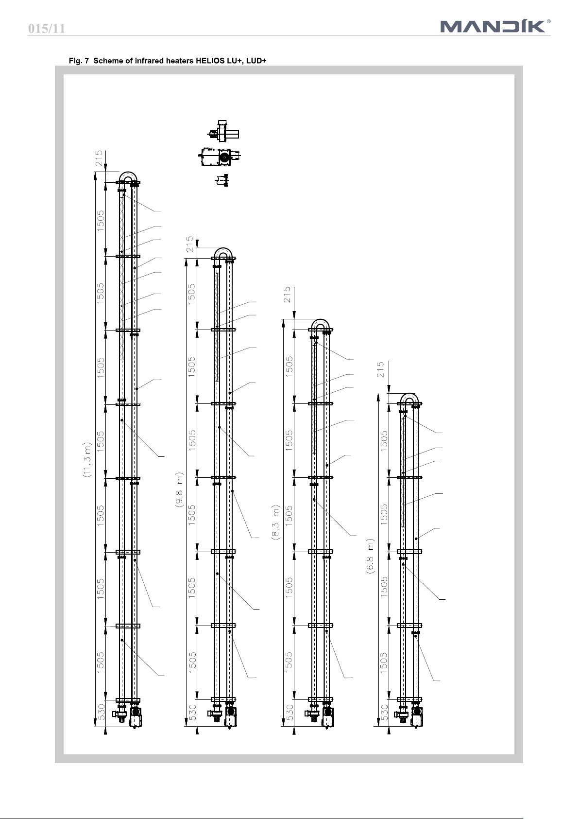
The infrared heater HELIOS consists of the following main parts:
●
● with hinges and the radiant heating tubes "U" or "I"
The basic design of the burner box is scalded by the throat for the external suction in the upper part of
the burner box. If the combustion air supply system is not connected, it is an open gas appliance. Thus,
infrared heaters can only be used in a basic (normal) environment according to the according to the
relevant standard. In order to be considered as a closed gas appliance, the radiator must be connected
to outdoor air intake system.
● Infrared heater operation is controlled by the located in the burner box.
● After connecting to the el. network, first the basic test of the connected devices to the automatic is
performed and if everything is OK, the exhaust fan is activated.
● After the fan starts and a vacuum is evoked in the burner chamber, the differential air manostat is
switched. The manostat senses the pressure differential caused by the exhaust fan.
● When the manostat is switched on, the venting time (approx. 50 s) starts to run, this is used to
ventilate the flue gas exhaust pipe and heating tubes.
● After this ventilation time, the electromagnetic double valve is opened and gas is injected into the
burner. At the same time, the ignition system is put into operation by the automatic system.
● The ignition of the gas mixture in the burner is detected by the ionisation electrode.
● If the gas mixture in the burner is not ignited within 5 seconds, the valve closes the gas supply and
the unburned gas / air mixture is vented through the exhaust fan during the next ventilation time. After
it has elapsed, the automation runs two more ignition cycles.
● If no flame is detected during the third ignition cycle, the automatic switches into the fault mode and
the red indicator “Burner Failure” light on.
● Further start is possible after unlocking the fault condition by disconnecting and reconnecting to the
power supply.
● After putting the burner into operation and igniting the gas mixture, the green indicator "Power
supply" and orange indicator "Burner Operation" lights up.

4
440
350
538
200
425
290
15°
600
Size, type 10-U+ 10-U/15+ – – – –
Weight [kg] 77,5 80,4 – – – –
Size, type 20-U+ 20-U/15+ 20-I+ 20-I/15+ 20-LU+ 20-LU/15+
Weight [kg] 107,1 111,3 124,1 130,7 135,8 141,4
Size, type 30-U+ 30-U/15+ 30-I+ 30-I/15+ 30-LU+ 30-LU/15+
Weight [kg] 137 142,6 160,1 168,8 163,9 170,8
Size, type 40-U+ 40-U/15+ 40-I+ 40-I/15+ 40-LU+ 40-LU/15+
Weight [kg] 163,9 170,4 196,1 209,6 189,9 198,2
Size, type – – – – 50-LU+ 50-LU/15+
Weight [kg] – – – – 220 229,7
The atmospheric burner control is single-stage or two-stage.
Infrared heater with single-stage burner works in on-off mode, two-stage burner of the infrared heater
operates in off mode - reduced power - full power.
The main advantages of the two-stage burner control include reducing burner start-up frequency, better
temperature distribution in the heated space and reduced energy consumption.
nfrared radiators HELIOS are divided in terms of installation and used reflector:
with reflectors fitted with hinges in version of hanging under the ceiling
● with reflectors fitted with hinges
Reflectors are supplied with insulation (thermal insulation, covered by a cover made of galvanized sheet
metal).
15°
241,5
408
260
340
200
250

5
Key:
6 Hinge I type 6
7 Hinge I type 7
8 Hinge I type 8
9 Hinge I type 9
A Stainless steel tube INOX 3080 mm
B Stainless steel tube INOX 1580 mm
E
Black tube 4595 mm - 1 socket
F Black tube 3090 mm - 1 socket
H
Black tube 3290 mm - 1 socket
I
Black tube 4595 mm - 2 sockets
K
Black tube 3090 mm - 2 sockets
O Wire eye for spinners
V Spinner
Burner box ''HS''
Exhaust box ''OS''
Socket tube joint
with clamp
V
O
V
H
E
I
A
A
K
F
V
O
V
H
V
O
V
H
I
B
HELIOS 40 I+
HELIOS 30 I+
HELIOS 20 I+

6
Key:
1 Hinge U type 1
2 Hinge U type 2
3 Hinge U type 3
4 Hinge U type 4
5 Hinge U type 5
A Stainless steel tube INOX 3080 mm
B
Stainless steel tube INOX 1580 mm
E Black tube 4595 mm - 1 socket
F Black tube 3090 mm - 1 socket
G
Black tube 1585 mm - 1 socket
I
Black tube 4595 mm - 2 sockets
K Black tube 3090 mm - 2 sockets
O Wire eye for spinners
V Spinner
Burner box ''HS''
Exhaust box ''OS''
Socket tube joint
with clamp
HELIOS 40 U+
HELIOS 30 U+
HELIOS 20 U+
HELIOS 10 U+

7
Key:
1 Hinge U type 1
2 Hinge U type 2
3 Hinge U type 3
4 Hinge U type 4
5 Hinge U type 5
A Stainless steel tube INOX 3080 mm
B
Stainless steel tube INOX 1580 mm
C Stainless steel tube INOX 4580 mm
E Black tube 4595 mm - 1 socket
F Black tube 3090 mm - 1 socket
G
Black tube 1585 mm - 1 socket
I
Black tube 4595 mm - 2 sockets
K Black tube 3090 mm - 2 sockets
O Wire eye for spinners
V Spinner
Burner box ''HS''
Exhaust box ''OS''
Socket tube joint
with clamp
35
13
3
2
1
1
1
1
4
4
4
4
2
2
23
3
33
3
3
5
5
5
K
F
F
C
E
K
E
AAB
EI
F
F
V
V
O
I
F
V
V
O
F
V
V
O
F
E
V
V
O
V
O
HELIOS 50 LU+
HELIOS 40 LU+
HELIOS 30 LU+
HELIOS 20 LU+

8
Suspension methods:
1. Dark tube infrared heaters can be suspended on suitable structure by means of chains or strings and
snap-hooks or tie rods.
2. According to the picture 8 it is necessary to fix the infrared heater at least on two places by using an
appropriate way so that the device cannot be turned around.
3. Due to the thermal expansion, the infrared heater can not be fixed directly to the supporting structure.
4. It is necessary to keep safe distance from flammable objects and walls (Fig. 9, 10).
When installing the heater over the runway of bridge crane, it is necessary to use the protection of
electrical power installation of the crane against excessive heat.

9
The flue gas duct must be in accordance with applicable standards and regulations.
Minimum internal diameter of the pipeline for Helios 10 to Helios 40 is 100 mm, for Helios 50 is
internal diameter of the pipeline 125 mm.
Connecting of the combustion gases to the ventilator must be demountable.
The duct system must prevent the condensate from penetration into the exhaust pipeline.
The duct system must be terminated freely in the exposed position so that the flue gases cannot
face any resistance, and also that combustion products cannot return back to the building through
windows.
The material of flue gases exhaust must be resistant to corrosion and against flue gases tempera-
ture according to relevant standards.
Opening for flue gases measurement is placed according to heater configuration, for heaters without
economizer the opening is in the first part of the duct immediately after the heater, for heaters with
economizer, the opening is in the first part of the flue duct immediately after the economizer.
For pressure losses of individual flue system components see following tables.
Total pressure loss of flue system can be calculated as sum of pressure losses of all components used.
1,5 1,5 2 2 4 16 23 3 4 5 2
2 3 4 4,5 7 23 31 5 7 8 4
3 4 6 7 11 29 35 9 11 13 6
1 1,5 3 3,5 5,5 16 18 4,5 5,5 6,5 3
3,5 4,5 7 8 14 35 44 11 14 16 7
1,5 2 4 4,5 8 19 22 5 6 8 4
2 3 6 6 12 27 32 7 9 12 6
DN 100 DN 100 DN 100 DN 100
- DN 100 - DN 100
DN 100 DN 100 DN 100 DN 100
- DN 100 - DN 100
DN 125 DN 100 DN 100 DN 100
- DN 100 - DN 100
DN 125 DN 100 DN 100 DN 100
DN 125 DN 125 DN 130 DN 130

10
DN 100 2 2,5 5 3,5 7 18 20 4 5 3
DN 100 3 4 6 6 11 26 29 6 8 5
DN 100 3,5 5 7 9 14 58 63 11 13 7
DN 125 2 3,5 5 6 10 20 20 8 9 5
DN 100 4 6 8 11 16 102 112 14 16 8
DN 125 3 4 6 6 11 35 35 10 11 6
DN 125 4 6 9 10 16 51 51 15 16 9
1 Helios heater
2 Tube with throat
3 Exhaust head
horizontal
1
23
2%
1
2
3
4
3
6
7354
2%
1 HELIOS heater
2 Condensate trap
3 Tube with throat
4 Bend
5
Join female-female
6
Exhaust head horizontal
7
Air intake head

11
1
4
3
5
2
1
3
3
5
2
3
4
1 HELIOS heater
2 Condensate trap
3 Tube with throat
4 Flexible duct Al
5 Coaxial chimney
vertical
1 HELIOS heater
2 Condensate trap
3 Tube with throat
4 Exhaust head vertical
5
Air intake head

12
19,9 36,5 41,0
18,5 33,9 38,2
19,9 33,0 41,0
18,0 33,2 37,3
16,7 30,8 34,8
18,0 30,0 37,3
230/50
100
4
17 - 26
28 - 50
2,07 3,84 4,25
2,15 3,98 4,40
1,51 2,48 3,09
4,0 5,0 5,5
2,6 3,3 3,8
9,5 11,5 10,5
13 14 13,5
25 23 21
10 13 16
0,018 0,028 0,031
max. 350 m3.h-1
max. 360 Pa
Min. 1000 mm
Min. 2000 mm
Min. 500 mm
The flue gas exhaust is forced by the flue
gas duct inside the building. The appliance
is classified according to the flue into
design version A . The design and installa-
tion of the flue gas exhaust must comply
according the correct norm.
When installing the heater in design A in
enclosed space, it is necessary to ensure
forced ventilation with min. 10 m / h for
each installed kW power consumption of
the heater in design A and it is necessary
to ensure that the device will stop in the
case of non-functional ventilation.
If inclined heaters are installed, rotate the
exhaust cabinet so that the flue gas is
directed vertically upwards.
3
2
2
2

13
12,5 19,9 19,9 33,0 33,0 41,0 41,0
11,6 18,5 18,5 30,7 30,7 38,2 38,2
12,0 19,9 19,9 33,0 33,0 41,0 41,0
– – 17,5 –29,0 –36,0
– – 15,9 –26,4 –32,8
– – 17,5 –29,0 –36,0
11,3 17,6 17,6 29,0 29,0 36,1 36,1
10,5 16,3 16,3 27,0 27,0 33,6 33,6
10,9 17,6 17,6 29,0 29,0 36,0 36,0
– – 15,4 –24,8 –31,3
– – 14,0 –26,7 –28,9
– – 15,4 –24,8 –31,3
230/50
100
4
17 - 26
28 - 50
1,26 2,07 2,07 3,43 3,43 4,25 4,25
1,30 2,15 2,15 3,55 3,55 4,40 4,40
0,91 1,51 1,51 2,48 2,48 3,09 3,09
– – 1,82 –3,01 –3,74
– – 2,07 –3,43 –4,25
– – 1,33 –2,18 –2,72
3,0 4,0 5,0 5,5
1,9 2,6 3,3 3,8
10 9,5 9,5 10 10 10,5 10,5
13,0 13 13 13 13 13,5 13,5
27,0 25 25 23 23 21 21
– – 7,5 –8,0 –8,2
– – 9,5 –10,0 –10,5
– – 19,0 –18,5 –16,5
3,8 5,3 6,8 8,3
0,009 0,015 0,025 0,030
max.
216
m3.h-1
max. 350 m3.h-1
max.
280
Pa
max. 360 Pa

14
19,9 19,9 33,0 33,0 41,0 41,0 49,5 49,5
18,5 18,5 30,7 30,7 38,2 38,2 46,1 46,1
19,9 19,9 33,0 33,0 41,0 41,0 47,9 47,9
–17,5 –29,0 –36,0 –43,6
–15,9 –26,4 –32,8 –40,6
–17,5 –29,0 –36,0 –43,6
18,0 18,0 30,0 30,0 37,3 37,3 45,0 45,0
16,7 16,7 27,9 27,9 34,8 34,8 41,9 41,9
18,0 18,0 30,0 30,0 37,3 37,3 43,6 43,6
–15,6 –25,5 –31,3 –38,4
–14,1 –23,5 –29,2 –36,1
–15,5 –25,5 –31,3 –38,4
230/50
100
4
17 - 26
28 - 50
2,07 2,07 3,43 3,43 4,25 4,25 5,14 5,14
2,15 2,15 3,55 3,55 4,40 4,40 5,32 5,32
1,51 1,51 2,48 2,48 3,09 3,09 3,60 3,60
–1,82 –3,02 –3,74 –4,52
–2,07 –3,43 –4,27 –4,70
–1,33 –2,18 –2,72 –3,30
4,0 5,0 5,5 6,2
2,6 3,3 3,8 4,2
9,5 9,5 10 10 10,5 10,5 10,5 10,5
13 13 13 13 13,5 13,5 13,5 13,5
25 25 23 23 21 21 17 17
–7,5 –8,0 –8,2 –8,2
–9,5 –10,0 –10,5 –10,5
–19,0 –18,5 –16,5 –14,5
6,8 8,3 9,8 11,3
0,015 0,025 0,030 0,039
max.
216
m3.h-1
max. 350 m3.h-1
max.
280
Pa
max. 360 Pa

15
1
2
3
4
5
6
7
Key:
1 Inner tube (plug in throat)
2 Outer tube with throat
3 Strap M12
4 Tenon
5 Bowl buckle
6 Wascher 13
7 Nut M12
●Burner box
●Exhaust (ventilation) box
●Connecting cable with connector
●Radiant pipes
●Pipe connections, arch
●Hinges with fixing straps
●Reflectors
●Connecting material
●Remote control box, connecting cables
●Accessories, auxiliary fastening and connecting material
●Venting or combustion air inlet pipeline
Before starting installation, make sure that local condition regarding gas line, fuel and its pressure and
heater setting are compatible.
Installation of the heater must be carried out in such way so that an adequate space for servicing and
adjustment is maintained (Fig. 9, 10). There must be ensured sufficient air exchange in the building to
allow for good combustion of gas. The amount of combustion air for the infrared heaters must meet
applicable standards. For installation of heaters in dusty environment, installation of duct supplying the
combustion air from outside (Closed appliance) is strongly recommended. The installation must comply
with applicable standards and regulations and with this installation manual.
Infrared heaters cannot be installed in places where there is a risk of fire or explosion or high levels of
flammable dust.
Infrared heaters HELIOS can be used for heating in public areas where this type of heating is permitted
by legislation. It is necessary to comply with the regulations for installation in these areas.
Connect the radiant pipes and with U and LU shaped heaters the arch by pushing into the sockets
up to the bottom according to the respective assembly diagram. Before joining the arch to the pipes,
first place the hinge with pate. Every time before joining new piece of radiant tube, put the hinges
according to the assembly diagram of the respective heater on the assembled part of the heater. The
hinges cannot be pulled over the installed socked pipe connection with clamp. Only after the hinges
are put on place, lock the socked pipe connection with clamp. The clamps have to be tightened
firmly, recommended torque is 20 Nm. – the connection has to be firm and tight.

16
2. Fasten the hinges onto the radiant tube at precise spacing and according to type of the infrared
heater and relevant installation drawing (Figure 5, 6, 7). Place the hinge with plate at the beginning
and end of the radiant tube!
3. Attach the reflector to the hinge. Check the dimensions according to Figure 1 to 4. Insulated reflector
holders mounted on the hinge- see Fig. 31, 32, 34, 35.
1
1
Radiant tube black
3
Hinge U type 5
2
Clamp
4
Arch 102/180
4
3
2
1
Radiant tube black
3
Hinge U type 5 5 Tube INOX
2
Clamp
4
Arch 102/180 6
Radiant tube black - 2 sockets
1
4
3
2
2
5
6
3
2
4
1
2
1 Tube INOX 3
Radiant tube black - 2 sockets
2 Clamp 4 Radiant tube black 3290 mm
1. Insert the tube into the throat so that the holes in the tube and in the throat overlap.
2. Insert a tenon into the hole and secure the bowl buckle and strap.
3. Tighten the nuts of the strap to 20 nm.

17
Hinge „U“ type 2
(without opening for
a roller, without
plate)
1×
Expansion insert 1×
Strap 2×
Washer 6.4 4×
Nut M6 4×
1
Radiant tube
102x2 black
3
Washer 6.4
5
Place the expansion
insert on the hinge
7
Hinge "U" with
expansion insert
2
Nut M6
4
Hanging point
6
Strap 102
6
1
1
7
4
4
5
2
3
Hinge „U“ type 2
(without opening for
a roller, without
plate)
1×
Strap 2×
Washer 6.4 4×
Nut M6 4×
5
4
1
1
6
4
1
Radiant tube
102x2 black
3
Washer 6.4
6
Strap 102
2
Nut M6
4
Hanging point
7
Hinge "U"
2
3
Hinge „U“ type 1
(with hole for roller,
without plate)
1×
Expansion insert 1×
Roller 1×
Strap 1×
Supporting rod 2×
Washer 6.4 6×
Nut M6 6×
2
4
5
6
7
8
5
9
1
7
10
1 Radiant tube
102x2 black
3 Washer 6.4 5 Supporting rod 7 Hanging point
9
Strap 102
2 Nut M6 4 Roller 6
Place the expansion
insert on the hinge
8 Radiant tube
102x2 INOX
10 Hinge "U" with expansion
insert and roller
3

18
Hinge „U“ type 3
(with hole for roller,
with plate)
1×
Strap 2×
Washer 6.4 4×
Nut M6 4×
1
Radiant tube
102x2 black
3
Washer 6.4
5
Strap 102
7
Hinge "U" with plate
2
Nut M6
4
Hanging point
6
Plate
1
5
1
7
4
6
4
2
3
Hinge „I“ type 1
(without plate) 1×
Expansion insert 1×
Strap 1×
Washer 6.4 2×
Nut M6 2×
1
Radiant tube 102x2
black or INOX
3
Washer 6.4
5
Place the expansion
insert on the hinge
7
Protection tube for ca-
ble connecting
2
Nut M6
4
Hanging point
6
Strap 102
8
Hinge "I" with expan-
sion insert
1
4
7
6
5
8
4
3
2
2
1
Radiant tube
102x2 black
3
Washer 6.4
5
Supporting rod
7
Hanging point
9
Strap 102
11
Hinge "U" with expansion
insert, roller and plate
2
Nut M6
4
Roller
6
Place the expansion
insert on the hinge
8
Radiant tube
INOX
10
Plate
2
3
6
5
7
8
5
9
1
11
7
10
4
Hinge „U“ type 3
(with hole for roller,
with plate)
1×
Expansion insert 1×
Roller 1×
Strap 1×
Supporting rod 2×
Washer 6.4 6×
Nut M6 6×

19
Hinge „I“ type 2
(with plate) 1×
Expansion insert 1×
Strap 1×
Washer 6.4 2×
Nut M6 2×
1
Radiant tube
102x2 black
3
Washer 6.4
5
Place the expansion
insert on the hinge
7
Plate 9
Protection tube for
cable connecting
2
Nut M6
4
Hanging point
6
Strap 102
8
Hinge "U" with expansion
insert and plate
7
4
8
1
4
9
6
5
3
2
2
Hinge „I“ type 2
(with plate) 1×
Strap 1×
Washer 6.4 2×
Nut M6 2×
1
Radiant tube
102x2 black
3
Washer 6.4
5
Plate
7
Protection tube for cable
connecting
2
Nut M6
4
Hanging point
6
Strap "U" 6
8
Hinge "U" with expansion
insert and plate
5
7
4
1
8
4
6
3
2
2
Hinge „I“ type 1
(without plate) 1×
Strap 1×
Washer 6.4 2×
Nut M6 2×
1
Radiant tube 102x2
black
3
Washer 6.4
5
Strap 102
7
Hinge "I"
2
Nut M6
4
Hanging point
6
Protection tube for
cable connecting
4
5
6
4
1
7
3
2
2

20
1
Hinge "U"
3
Washer 6.4
5
Insulated reflector "U"
7
Holder of the insulated
reflector
2
Bolt M6x12
4
Nut M6
6
Frond washer 6.4
1
5
4
6
3
2
7
1
Radiant tube
102x2 black
3
Washer 6.4
+ Nut M6
5
Reflector U/15
7
Hinge "U" with
expansion insert
9 Reflector clap
2
Bolt M6
4
Hanging point
6
Strap 102
8
Additional Hinge "U/15"
3
8
6
1
4
1
5
7
4
2
9
1
Radiant tube
102x2 black
3
Washer 6.4
+ Nut M6
5
Roller 16
7
Reflector U/15 9 Radiant tube
102x2 INOX
11
Supporting
rod
13
Reflector
clap
2
Nut M6
4
Hanging point
6
Strap 102
8
Hinge "U" with
expansion insert
10
Supporting rod
with fin
12
Bolt M6
14
Additional
hinge U/15
1
4
o
8
6
10
9
7
3
5
2
12
4
11
14
13
Other manuals for HELIOS
1
Other Mandik Heater manuals
Popular Heater manuals by other brands

Polaris
Polaris PCDH 1115 Manual instruction

HOZAN
HOZAN H-601 instruction manual

THERMAL INTEGRATION
THERMAL INTEGRATION XCEL installation instructions

ARDES
ARDES AR449TI Instructions for use

Smith’s Environmental Products
Smith’s Environmental Products Eco-Powerad 500 Installation & user guide

Infiniton
Infiniton HCT-200 user manual