mangOH Green User manual

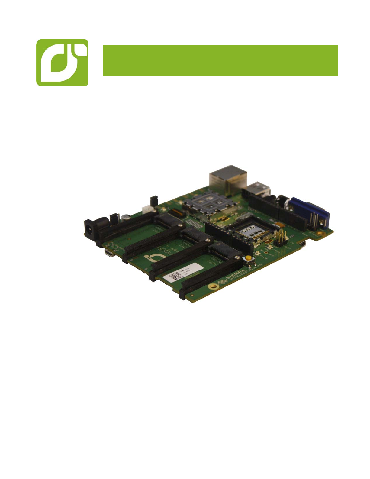
mangOH™ greenUser Guide
4117164
Rev 2
Contents subject to change

mangOH green User Guide
Rev 2 Jan.16 2 4117164
Important
Notice Due to the nature of wireless communications, transmission and reception of data can
never be guaranteed. Data may be delayed, corrupted (i.e., have errors) or be totally
lost. Although significant delays or losses of data are rare when wireless devices such
as the Sierra Wireless modem are used in a normal manner with a well-constructed
network, the Sierra Wireless modem should not be used in situations where failure to
transmit or receive data could result in damage of any kind to the user or any other
party, including but not limited to personal injury, death, or loss of property. Sierra
Wireless accepts no responsibility for damages of any kind resulting from delays or
errors in data transmitted or received using the Sierra Wireless modem, or for failure
of the Sierra Wireless modem to transmit or receive such data.
Safety and
Hazards Do not operate the Sierra Wireless modem in areas where blasting is in progress,
where explosive atmospheres may be present, near medical equipment, near life
support equipment, or any equipment which may be susceptible to any form of radio
interference. In such areas, the Sierra Wireless modem MUST BE POWERED OFF.
The Sierra Wireless modem can transmit signals that could interfere with this
equipment.
Do not operate the Sierra Wireless modem in any aircraft, whether the aircraft is on
the ground or in flight. In aircraft, the Sierra Wireless modem MUST BE POWERED
OFF. When operating, the Sierra Wireless modem can transmit signals that could
interfere with various onboard systems.
Note: Some airlines may permit the use of cellular phones while the aircraft is on the ground
and the door is open. Sierra Wireless modems may be used at this time.
The driver or operator of any vehicle should not operate the Sierra Wireless modem
while in control of a vehicle. Doing so will detract from the driver or operator's control
and operation of that vehicle. In some states and provinces, operating such
communications devices while in control of a vehicle is an offence.
Limitation of
Liability The information in this manual is subject to change without notice and does not
represent a commitment on the part of Sierra Wireless. SIERRA WIRELESS AND ITS
AFFILIATES SPECIFICALLY DISCLAIM LIABILITY FOR ANY AND ALL DIRECT,
INDIRECT, SPECIAL, GENERAL, INCIDENTAL, CONSEQUENTIAL, PUNITIVE OR
EXEMPLARY DAMAGES INCLUDING, BUT NOT LIMITED TO, LOSS OF PROFITS
OR REVENUE OR ANTICIPATED PROFITS OR REVENUE ARISING OUT OF THE
USE OR INABILITY TO USE ANY SIERRA WIRELESS PRODUCT, EVEN IF
SIERRA WIRELESS AND/OR ITS AFFILIATES HAS BEEN ADVISED OF THE
POSSIBILITY OF SUCH DAMAGES OR THEY ARE FORESEEABLE OR FOR
CLAIMS BY ANY THIRD PARTY.
Notwithstanding the foregoing, in no event shall Sierra Wireless and/or its affiliates
aggregate liability arising under or in connection with the Sierra Wireless product,
regardless of the number of events, occurrences, or claims giving rise to liability, be in
excess of the price paid by the purchaser for the Sierra Wireless product.

Preface
Rev 2 Jan.16 3 4117164
Patents This product may contain technology developed by or for Sierra Wireless Inc.
This product includes technology licensed from QUALCOMM®.
This product is manufactured or sold by Sierra Wireless Inc. or its affiliates under one
or more patents licensed from InterDigital Group and MMP Portfolio Licensing.
Document
details Title: mangOH Green User Guide
Author: Sierra Wireless
Source: http://mangoh.io/
Copyright © 2016 Sierra Wireless. Licensed under the Creative Commons Attribution 4.0
license, http://creativecommons.org/licenses/by/4.0/
Disclaimer Indicate any modifications made to the original document.
Trademarks mangOH™ and the mangOH logo are trademarks of Sierra Wireless.
Other trademarks are the property of their respective owners.
Revision
History
Revision
number Release date Changes
1January 2016 Document Creation

Rev 2 Jan.16 4 4117164
Contents
Introduction . . . . . . . . . . . . . . . . . . . . . . . . . . . . . . . . . . . . . . . . . . . . . . . . . . . . . . . . . . . . . . . 6
mangOH green Components and Accessories . . . . . . . . . . . . . . . . . . . . . . . . . . . . . . . . . . 6
Setup and Installation. . . . . . . . . . . . . . . . . . . . . . . . . . . . . . . . . . . . . . . . . . . . . . . . . . . . . . . 9
Safe Handling Recommendations . . . . . . . . . . . . . . . . . . . . . . . . . . . . . . . . . . . . . . . . . . . . 9
Initial Setup . . . . . . . . . . . . . . . . . . . . . . . . . . . . . . . . . . . . . . . . . . . . . . . . . . . . . . . . . . . . 10
Hardware Setup and Operation . . . . . . . . . . . . . . . . . . . . . . . . . . . . . . . . . . . . . . . . . . . . . . 11
Insert/Remove Embedded Modules . . . . . . . . . . . . . . . . . . . . . . . . . . . . . . . . . . . . . . . . . 11
Power Supply. . . . . . . . . . . . . . . . . . . . . . . . . . . . . . . . . . . . . . . . . . . . . . . . . . . . . . . . . . . 14
Select Primary Power Supply . . . . . . . . . . . . . . . . . . . . . . . . . . . . . . . . . . . . . . . . . . . .15
Connect Battery Backup . . . . . . . . . . . . . . . . . . . . . . . . . . . . . . . . . . . . . . . . . . . . . . . .16
RTC Capacitor . . . . . . . . . . . . . . . . . . . . . . . . . . . . . . . . . . . . . . . . . . . . . . . . . . . . . . . .17
Insert SIM Card(s) . . . . . . . . . . . . . . . . . . . . . . . . . . . . . . . . . . . . . . . . . . . . . . . . . . . . . . . 17
Insert microSD Card . . . . . . . . . . . . . . . . . . . . . . . . . . . . . . . . . . . . . . . . . . . . . . . . . . . . . 19
Connect Antenna(s). . . . . . . . . . . . . . . . . . . . . . . . . . . . . . . . . . . . . . . . . . . . . . . . . . . . . . 20
Insert/Remove IoT Modules . . . . . . . . . . . . . . . . . . . . . . . . . . . . . . . . . . . . . . . . . . . . . . . 22
Arduino Leonardo . . . . . . . . . . . . . . . . . . . . . . . . . . . . . . . . . . . . . . . . . . . . . . . . . . . . . . . 23
Connect Arduino Shield . . . . . . . . . . . . . . . . . . . . . . . . . . . . . . . . . . . . . . . . . . . . . . . . .24
Audio Connection. . . . . . . . . . . . . . . . . . . . . . . . . . . . . . . . . . . . . . . . . . . . . . . . . . . . . . . . 25
Ethernet Connection . . . . . . . . . . . . . . . . . . . . . . . . . . . . . . . . . . . . . . . . . . . . . . . . . . . . . 26
USB Host Connection . . . . . . . . . . . . . . . . . . . . . . . . . . . . . . . . . . . . . . . . . . . . . . . . . . . . 27
RS-232 Console Output Connection . . . . . . . . . . . . . . . . . . . . . . . . . . . . . . . . . . . . . . . . . 27
LED Indicators . . . . . . . . . . . . . . . . . . . . . . . . . . . . . . . . . . . . . . . . . . . . . . . . . . . . . . . . . . 28
Reset Switches . . . . . . . . . . . . . . . . . . . . . . . . . . . . . . . . . . . . . . . . . . . . . . . . . . . . . . . . . 29
mangOH green Configuration . . . . . . . . . . . . . . . . . . . . . . . . . . . . . . . . . . . . . . . . . . . . . . 30
Default Configuration . . . . . . . . . . . . . . . . . . . . . . . . . . . . . . . . . . . . . . . . . . . . . . . . . . .30
Switch and Jumper Configuration Options . . . . . . . . . . . . . . . . . . . . . . . . . . . . . . . . . .31

Contents
Rev 2 Jan.16 5 4117164
Software Setup . . . . . . . . . . . . . . . . . . . . . . . . . . . . . . . . . . . . . . . . . . . . . . . . . . . . . . . . . . . 35
Install / Update Windows Driver. . . . . . . . . . . . . . . . . . . . . . . . . . . . . . . . . . . . . . . . . . . . . 35
Install a Terminal Emulator . . . . . . . . . . . . . . . . . . . . . . . . . . . . . . . . . . . . . . . . . . . . . . . . 36
Install the Arduino IDE. . . . . . . . . . . . . . . . . . . . . . . . . . . . . . . . . . . . . . . . . . . . . . . . . . . . 36
Install the Legato Developer Studio. . . . . . . . . . . . . . . . . . . . . . . . . . . . . . . . . . . . . . . . . . 36
Download Firmware Updates. . . . . . . . . . . . . . . . . . . . . . . . . . . . . . . . . . . . . . . . . . . . . . . 36
Write Your First Program. . . . . . . . . . . . . . . . . . . . . . . . . . . . . . . . . . . . . . . . . . . . . . . . . . 36

Rev 2 Jan.16 6 4117164
1
1: Introduction
This user guide explains how to set up and begin using the mangOH™ green with
CF3 (Common Flexible Form Factor) modules.
Once you have the mangOH green set up, visit mangoh.io for developer
documentation, code samples, and other materials.
mangOH green Components and
Accessories
Table 1-1 details the required and optional components needed to begin using the
mangOH green in your development environment. Some of these components are
available in mangOH development kits (kit contents are supplier-dependent).
Table 1-1: mangOH green Components
Item Details
mangOH green Pre-configured development board.
The mangOH green supports CF3 modules.
CF3 module(s)
(See Table 1-2 on page 8
for a list of compatible
Sierra Wireless modules.)
•Primary (required)—Used in the primary CF3 socket, the module
includes a cellular modem and an application processor running
Legato, an open source embedded platform built on Linux for
hosting IoT applications (see legato.io for details).
•Secondary (optional)—[Future Use] Used in the secondary CF3
socket, the module includes a cellular modem that must be associated to an application
processor in the primary CF3 socket.
(In this socket, only the inner ring of pins of the CF3 footprint are used.)
CF3 module cover and
cover removal tool Industrial-quality snap-in module cover, plus cover removal
tool to disconnect the cover from the mangOH green
(Note: The cover and tool shown are for WP-series
modules. A similar cover and tool (not displayed) are used
for HL-series modules.)
Micro-USB cable Connects computer to the mangOH green for
communication and to provide power for non-transmitting
tests.

Introduction
Rev 2 Jan.16 7 4117164
Power supply •Output voltage: 4.5V to 17V
•10 W or higher
•The mangOH green will operate with USB power, but
DC power may be required to make and establish a
full-speed mobile network connection.
Antenna Main RF antenna
GNSS Antenna GNSS (GPS/GLONASS) active antenna
Eurocard case and
mangOH green faceplates The mangOH green fits in a Eurocard standard size casing
(100x120mm).
3D-printable files for faceplates are available at mangoh.io.
Mini-USB cable Connects computer directly to the Arduino Leonardo circuit integrated
into the mangOH green
Mini-SIM card Mini-SIM card with an active account, or a test card for use with a call box.
Note: Throughout this document, ‘SIM’ refers to ‘SIM’, ‘USIM’, and ‘UIM’.
Micro-SIM card Micro-SIM card with an active account, or a test card for use with a call box.
The micro-SIM is used only if the CF3 module supports dual-SIMs (selecting
either the mini-SIM or the micro-SIM for use at a given time). It uses the dual
SIM/SD connector.
Audio cable (3.5 mm) Audio cable or headset
Ethernet cable Ethernet cable (Cat5 or better) for use with the mangOH green’s
100 Mbps Ethernet connector
Table 1-1: mangOH green Components
Item Details

mangOH green User Guide
Rev 2 Jan.16 8 4117164
RS-232 DB9 cable Serial cable used for console output (male connector required on
mangOH end)
Battery Rechargeable Li-Ion or Li-Polymer battery (3V7 nominal) for
use when USB/DC power supply is unavailable
Arduino shields Plug-in boards for the mangOH green’s integrated Arduino
Leonardo circuit
Table 1-1: mangOH green Components
Item Details
Table 1-2: mangOH-compatible CF3 Modulesa
Module series Notes
AirPrime WP8548
AirPrime WP75xx The mangOH schematic (available at mango.io), describes all
interfaces that are supported by the mangOH green.
The following table identifies signals that are currently not
available on WP85xx/WP75xx-series modules.
Pin # mangOH Name Primary
CF3 Name WP85/75 Name
92 SPI2CLK SPI2CLK Reserved
93 SPI2_MOSI SPI2_MOSI Reserved
94 SPI2_MISO SPI2_MISO Reserved
95 SPI2_MRDY SPI2_CS0 Reserved
98 UART2_RTS UART2_RTS Reserved
99 UART2_CTS UART2_CTS Reserved
100 GPIO_Lowpower2 GPIO34 Reserved
101 GPIO_Lowpower1 GPIO35 Reserved
102 GPIO20/SWD_CLK GPIO36 Reserved
103 GPIO31/SWD_DIO GPIO37 Reserved
107 ADC2 ADC2 Reserved
108 ADC3 ADC3 Reserved
147 IOT2_GIO4 GPIO21 GPIO21
a. Refer to Product Technical Specification documents for detailed module information.

Rev 2 Jan.16 9 4117164
2
2: Setup and Installation
Safe Handling Recommendations
To help prevent accidental damage to the mangOH green:
•Use safe ESD-handling practices (such as wearing proper ESD straps) to avoid
possible ESD damage.
•Avoid touching the CF3 module sockets (J200, J601). These pins can be
damaged if they catch on clothing or other materials.
Figure 2-1: Safe Handling Recommendations—CF3 Socket Locations (Do Not Touch)
•Mount the mangOH green in a case, or attach standoffs (not included) to the
mounting holes at each corner of the board to avoid damage to components on
the bottom side of the board.
Figure 2-2: Case-mounted mangOH green
1—J200 (Primary)
2—J601 (Secondary)

mangOH green User Guide
Rev 2 Jan.16 10 4117164
Initial Setup
To begin using the mangOH green, set up your hardware and software:
1. Insert a suitable CF3 module in the primary socket. See Insert/Remove
Embedded Modules on page 11.
2. Select Primary Power Supply. See page 15.
3. If you will be establishing a mobile network connection, insert a mini-SIM. See
Insert SIM Card(s) on page 17.
4. Connect Antenna(s). See page 20.
5. Install / Update Windows Driver. See page 35.
6. Connect the mangOH green to your computer using the USB cable provided.
If you selected USB power in Step 2, the power LED lights up.
7. If you selected the DC power supply in Step 2, plug a DC wall adapter into the DC
barrel jack. (The wall adapter must meet the requirements in Table 1-1 on
page 6.)
The power LED lights up when power is supplied.
8. Install a Terminal Emulator. See page 36.
The mangOH green is now ready to be used.
•For information on additional hardware features, see Hardware Setup and
Operation on page 11.
•For instructions on writing a program, see Write Your First Program on page 36.

Rev 2 Jan.16 11 4117164
3
3: Hardware Setup and Operation
This chapter describes how to install various components on the mangOH green, and
how to configure and control features using connectors and switches.
Insert/Remove Embedded Modules
The mangOH green has two CF3 module sockets
•Primary (J200)—The primary module includes a wireless modem and application
processor. All pins are used.
•Secondary (J601)—The secondary module, if used, includes a wireless modem
that is associated with the primary module. Only the inner ring pins (of the CF3
footprint) are used.
To insert a CF3 module:
1. Place the mangOH green face-up.
Figure 3-1: mangOH green—Top View
1—J200 (Primary)
2—J601 (Secondary)

mangOH green User Guide
Rev 2 Jan.16 12 4117164
2. Hold the module above the socket and line up the polarity marks on the module
and socket. (Primary module installation shown.)
Figure 3-2: CF3 Module Positioning
3. Place the module onto the socket. The module should drop into place when you
have it aligned properly. Do not insert at an angle as this may damage the socket
pins.
Figure 3-3: CF3 Module Inserted

Hardware Setup and Operation
Rev 2 Jan.16 13 4117164
4. Attach the module cover:
a. Hold the module cover above the CF3 module and line up the polarity marks
on the module and cover.
Figure 3-4: Installing Module Cover
b. Place the cover on the module, then press down carefully until you hear the
cover click into place. Make sure all sides of the cover have clicked into place.
Figure 3-5: Installing Module Cover
To remove a CF3 module (primary module displayed below):
1. Remove the module cover using the module cover removal tool—Starting at one
corner, insert the tool in the pair of holes and carefully pry the cover away from
the module.
2. Repeat at the other locations (there are pairs of pry holes on each side).

mangOH green User Guide
Rev 2 Jan.16 14 4117164
Figure 3-6: Removing the Module Cover
3. Lift the cover off the module.
4. Carefully pinch the module and pull it straight up out of the socket.
Power Supply
The mangOH green has the following supplies:
Table 3-1: mangOH green Power Supplies
Supply Details
Primary DC power Primary (Required if you want to maintain a full-
speed mobile network data connection)
USB Primary
Note: USB current (500 mA) is sufficient for non-
transmitting tests, but may not be enough to satisfy
full power requirements of the mangOH green.
Backup Battery An optional Li-Ion or Li-polymer (3V7 nominal)
rechargeable battery can be installed to power the
board if the primary power supply fails.

Hardware Setup and Operation
Rev 2 Jan.16 15 4117164
Select Primary Power Supply
To select the primary power supply:
1. Place the mangOH green face-up and locate the power supply jumper pins
(CN1204).
Figure 3-7: Power Supply Select (CN1204)
2. Select the power source:
·USB power—Place a jumper across the two pins farthest from the DC power
jack.
·DC power—Place a jumper across the pins closest to the DC power jack.
Figure 3-8: Power Source Select (DC power shown)
1—Power supply select (CN1204)
2—DCjack
3—micro-USB connector
(bottom side of board)
1—USB select (left + center pins)
2—DC select (center + right pins)

mangOH green User Guide
Rev 2 Jan.16 16 4117164
Connect Battery Backup
Optionally, you can connect a rechargeable Li-Ion/Li-Polymer battery to the mangOH
green to provide uninterrupted power in the event that the primary power supply (DC
or USB) fails.
If a jumper is placed on CN1201, the mangOH green recharges the battery and then
provides a trickle charge to maintain the battery’s full charge.
To connect a rechargeable Li-Ion/Li-Polymer battery to the mangOH green:
1. Connect the battery to CN1202.
Figure 3-9: Battery Backup (CN1202/CN1203)
Figure 3-10: mangOH green With Rechargeable Battery Connected
2. If you want the battery to recharge while connected to the board, place a jumper
across the pins on CN1203 (Recharge select).
Caution: If a rechargeable battery is not connected to the board, make sure to remove the
jumper from CN1203.
1—Recharge select (CN1203)
2—Rechargeable battery connector (CN1202)
1—Jumper on Recharge select (CN1203)
Battery recharges when mangOH green
is powered by DC or USB.
(DC power shown)
-/+ —Negative and positive terminals of
rechargeable battery connector (CN1202)

Hardware Setup and Operation
Rev 2 Jan.16 17 4117164
Caution: The board is designed to use a rechargeable Li-Ion or Li-polymer battery. Regular
(non-rechargeable) batteries are NOT recommended. However, if a regular battery is used, DO
NOT place a jumper on CN1203 as this will damage the battery and possibly the board.
RTC Capacitor
The mangOH green has a capacitor that maintains the RTC.
To enable the ability to manually discharge the capacitor, install a switch on CN320.
The capacitor can then be discharged by pressing this switch.
Figure 3-11: RTC Capacitor
Insert SIM Card(s)
The mangOH green supports dual SIM functionality (if supported by the CF3 module).
To use a UMTS/LTE CF3 module to establish a mobile network connection, you must
install at least one SIM card:
•Live card(s) with active accounts, or
•Test card(s) for use with a call box (for example, an Agilent 8960 or
Rohde & Schwarz CMU200)
Table 3-2: SIM connectors
CF3
Interface Type Connect
or Details
UIM1 Mini-SIM CN801 Hot-swappable
By default, a SIM detect switch is activated when a
mini-SIM is inserted or removed. For details, see
Table 3-6 on page 30.
UIM2 Micro-SIM CN802 Not hot-swappable
1—RTC capacitor (C346)
2—Discharge switch location (CN320)

mangOH green User Guide
Rev 2 Jan.16 18 4117164
Note: A SIM card is not required if you want to connect to a LAN using the Ethernet port.
To install the SIM card(s):
1. Place the Dev Kit face-down (as shown).
Figure 3-12: SIM Connector and micro-SD Locations
2. Insert the SIM card(s) with contacts face-down into the desired slot(s)—note the
locations of the notched corners of the cards in Figure 3-13. (The mini-SIM is
inserted with the flat end first, and the micro-SIM is inserted with the notched end
first.)
Important: CN802 is a dual-connector—a micro-SIM can be placed in the lower slot,
and a micro-SD can be placed in the upper slot.
Figure 3-13: SIMs—Inserting
1—mini-SIM (CN801)
2—micro-SIM (CN802—bottom)
3—micro-SD (CN802—top)

Hardware Setup and Operation
Rev 2 Jan.16 19 4117164
Figure 3-14: SIMs—Inserted
Insert microSD Card
The mangOH green includes a microSD card slot in the top part of CN802.
To install a microSD card:
1. Place the Dev Kit face-down (as shown).
Figure 3-15: SIM Connector and micro-SD Locations
2. Insert the microSD card with contacts face-down into the top slot of CN802.
Important: CN802 is a dual-connector—a micro-SIM can be placed in the lower slot,
and a micro-SD can be placed in the upper slot.
1—mini-SIM (CN801)
2—micro-SIM (CN802—bottom)
3—micro-SD (CN802—top)

mangOH green User Guide
Rev 2 Jan.16 20 4117164
Figure 3-16: microSD—Inserting
Figure 3-17: microSD—Inserted
Connect Antenna(s)
The mangOH green includes three antenna ports for the primary CF3 module.
Note: If needed, the board can be configured to use SMA connectors. For details, see
Table 3-6 on page 30.
To connect an antenna to the Main, Diversity, or GNSS antenna connector:
1. Place the mangOH green face-up.
Table 3-3: Antenna Ports
Type Connectora
a. U.FL connectors
Details
Main CN307 Required to establish a mobile network data connection
Diversity CN304 Used only if primary CF3 supports diversity.
GNSS CN306 •Required to enable GNSS functionality
•Active
•3.3 V bias voltage
Other manuals for Green
1
Table of contents
Other mangOH Motherboard manuals