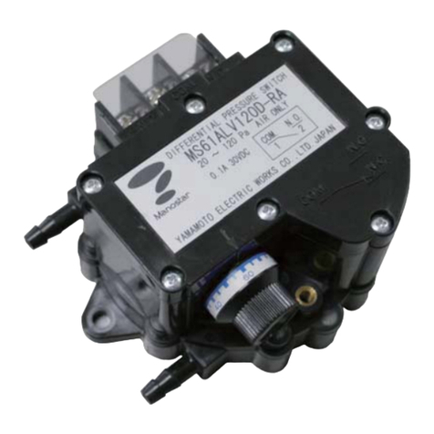
Manostar MS99 User manual

RoHS
READ THE INSTRUCTION MANUAL BEFORE USING
INSTRUCTION MANUAL
MANOSTAR SWITCH
MS99
No. TR-MS99-E02
1-2-3,Nishi-shiriike-cho,Nagata-ku,Kobe,Hyogo 653-0031 JAPAN
TEL. +81-78-631-6000 FAX. +81-78-631-6020

TABLE OF CONTENTS
PAGE
INTRODUCTION .............................................................................................................................. 1
Ⅰ.PRECAUTIONS ....................................................................................................................... 1
Ⅱ.THE NAME OF EACH PART ........................................................................................... 2
Ⅲ.INSTALLATION
1. Caution of service condition .................................................................................... 2
2. Installation of MS99 ....................................................................................................... 2
3. Installation position ........................................................................................................ 3
4. Wiring material ................................................................................................................... 3
5. Accessory for MS99 ...................................................................................................... 3
6. Accessory for type C ................................................................................................... 4
7. About an exchange of type C piping connector. ......................................... 5
8. Pressure of measurement and connection of piping ................................. 5
Ⅳ.SETTING OF PRESSURE
1. Switch contact configuration ................................................................................... 6
2. Setting of upper limit/ lower limit ........................................................................ 6
3. Setting the dial .................................................................................................................. 7
4. Reset time ........................................................................................................................... 7
Ⅴ.ABOUT BUILT-IN SWITCH
1. Material of contact ......................................................................................................... 8
2. About measured gas and contact failure .......................................................... 8
3. Protection of contact of switch ............................................................................. 9
Ⅵ.GENERAL PRECAUTIONS
1. Prohibition of common piping .............................................................................. 10
2. Prevention of clogged piping due to drain .................................................... 10
3. Measurement of high temperature gases ..................................................... 10
4. Errors caused by long distance piping ........................................................... 10
Ⅶ.PERIODIC INSPECTION ............................................................................................ 11
Ⅷ.PRODUCT WARRANTY ............................................................................................. 11

1
INTRODUCTION
Thank you very much for purchasing of "MANOSTAR SWITCH MS99".
△
!
Caution
To ensure your safety in using this instrument :
・Be sure to read the instruction manual carefully before using the instrument so that you
can use it properly.
Wrong use may result in failure of the instrument and lead to its damage and accident. This
manual should be kept in a proper place so that you can refer to it any time you need.
Ⅰ.PRECAUTIONS
△
!Warning
・Do not use the instrument where flammable gas is present.
The instrument is not explosion-proof. Do not use instruments in the circumstance where flammable gas is present. It
may cause explosion.
・Do not use the instrument at the place where corrosive gas is present.
The instrument is not corrosion resistance construction. Measuring corrosive gas may corrode the receiving element
and housing material of the instrument. It is expected that corrosive gas leaked out of the instrument will harm a
person.
・Do not apply the pressure to the instrument more than it can withstand.
The diaphragm and the retainer are broken and cause of injury or accident, etc. disaster if the pressure exceeding
withstanding pressure of the pressure receiving element is applied to the instrument. The case body and the
transparent cover of the instrument are broken and cause of injury or accident, etc. disaster if the pressure exceeding
withstanding pressure of the instrument body is applied to the instrument.
・The instrument is measurable for air and non-corrosive gas only.
The machine is exclusive use of dry air (90%RH or less). Using measuring the water or oil it may be damaged and
causes the accident.
・Avoid using where the instrument is subject to many vibration and impact.
Using the instrument where intensified vibration and impact may be damaged the instrument. It is expected that gas
leaks of the instrument which harms a parson.
・Do not exceed rated surrounding temperature, humidity and altitude in use.
Using the instrument by exceeding rated surrounding temperature and humidity and altitude it may be damaged and
cause the accident.
・Do not disassemble or reconstruct the instrument.
It may void the warranty.
・Do not exceed rated voltage in using
Using the instrument by exceeding rated voltage may cause fire or electric shock.
・Wire correctly.
Incorrect wiring may cause fire.
△
!Caution
・As to where to install and how to install this instrument, be sure to follow the instruction manual provided
so as to ensure a proper method.
・Use the instrument indoors.
・In case of not being installed in dry and well-kept clean locations, the instrument must be enclosed in box.
・Do not use organic solvent for cleaning.
Use a cloth soaked with water-diluted neutral detergent to wipe the surface of a product. Using of organic solvent
causes damage on the surface.
・Dropping the product.
Product is a precision instrument. If you drop the product, there is a possibility that the exterior, also the interior
mechanism damage.
・Removal of the piping
Please do not pull the pipe with a strong force. There is a possibility that the pipe cap is broken.
・MS99 acquires UL-approved as an open type enclosure.
For UL listing application, install MS99 in the system, and configure so that the entire system will be UL-approved.

2
Ⅱ.THE NAME OF EACH PART
・Type V ・Type C
(All except for the piping connector part is
common with type V)
Ⅲ.INSTALLATION
Before using this instrument, make sure if it is the type that you requested and meets the demand of the
environment, pressure and piping conditions where it is used, by specification.
1. Caution of service condition
a) Do not use the instrument in a place subjected to direct sunlight, vibration or shock, or excessive
moisture. In particular, vibration and shock to the instrument should shorten its life.
b) Use under the medium and ambient temperature from - 10 to + 50 ℃.
c) The instrument is not waterproof. Do not use it in a place subjected to rain, or other splashing water.
The product is equivalent to the protection class IP54, when mounted as below.
1)Use the cable clamp which matches the wire diameter of the wiring.
2)Please install it so that a gap doesn't occur between a cover and the body by a screw for cover
installation of an accessory.
※Please refer to the item of p.3 "5. Accessory for MS99" about cable clamp.
d) In installing the instrument, select the place where the ground is smooth and flat.
2. Installation of MS99
Panel cut size
△
!
Caution
・The tightening torque of the screw is 1 N・m.
・Do not apply excessive torque more than
stipulated value, otherwise it will damage the
body of the instrument.
Cover
Installation screw
for cover
Terminal screws
Pointer
Dial
Cable clamp holder
Installation plate
High pressure
side tube tap
Low pressure
side tube tap
(Interchangeable)
(Interchangeable)
High pressure
side piping
connector
Low pressure
side piping connector
2×φ5 or M4
90±0.3

3. Inst
a
M
u
A
f
4. Wiri
n
C
h
s
c
te
w
h
c
a
F
u
b
e
5. Acc
e
Used w
i
Ca
b
n
Use the
protecti
o
※When
C, it
c
inter
v
a
llation posi
t
ust be specif
i
f
ter inspectio
n
n
g material
h
oose the wi
r
c
rew of the
rmination of
h
ich matches
a
n be change
d
u
rther, an att
e
chosen fro
m
e
ssory for
M
In
aluminum,
i
th the install
b
le clamp (prod
u
ylon66,polypr
o
O
O
O
cable clamp be
o
n class IP54.
taking wiring
o
c
an't be install
e
v
ene.
△
!
Caution
U
t
ion
i
ed at time of
n
and adjust
m
r
ing material
d
product is
the crimpin
g
the general
M
d
by changing
achment poi
n
m
2 points.
M
S99
stallation pla
t
copper made
[
ation of the i
n
u
ced by OHM E
L
o
pylene,NBR
Product code
O
A-W15M-0
4
O
A-W15M-0
5
O
A-W15M-0
7
low so as to m
a
o
ut in the conn
e
e
d for a conne
c
se of in a po
s
5
°
Vertic
order.
m
ent in accor
d
d
epending on
M4. Wire
b
g
terminal (
O
M
4 screws.)
T
the directio
n
n
t of the cabl
e
t
e
[
installed ]
Product
c
ADPL99
n
strument bo
L
ECTRIC CO., L
T
made [ option
Suitable
diame
t
4
φ2
~
5
φ3
~
7
φ5
~
a
ke it equivale
n
e
ctor direction
c
tor and cable
c
s
ition other t
h
°
5°
0
°
90°
al plane
Vertica
l
3
d
ance with th
the load. Te
b
y performin
O
.D. less tha
T
he wiring dir
n
of the cove
r
e
clamp recei
p
c
ode
9
-01
dy.
T
D.)
]
wire
t
e
r
~
4
~
5
~
7
n
t to the
by type
c
lamp to
h
an the spec
1.
R
5°
5°
°
Horizo
n
l
Hor
pla
n
e specified in
rminal
g the
n φ8
e
ction
r
.
p
t can
p
o
ified is out o
f
Th
e
(W
h
in
s
R
emove the l
o
locknut is not
install the inst
r
n
tal
izontal
n
e
<Installation
>
s
tallation pos
C
o
o
lycarbonate-
m
f
accuracy w
a
e
wiring directi
o
h
en cable clam
s
talled.)
o
cknut. The
n
ecessary to
r
ument.
On installati
o
position is a
>
s
ition, and sh
i
o
ve
r
m
ade [ installe
d
a
rranty.
on
m
p, which is sol
d
2.The cable
c
by hand. A
t
the cable c
l
and, parts
a
(without a
g
may be da
m
tightening.
o
npanel,follo
w
vailable.
O
-
Cable cl
a
i
pped.
d
]
Product cod
e
TCA-99
d
separately, i
s
lamp screwed
t
t
that time, O-
l
amp is compr
e
a
re in contact
g
ap). Caution,
m
aged if too m
u
w
ing
-
ring
a
mp holder
e
s
t
o it,
ring o
f
e
ssed,
parts
u
ch

6. Accesso
Be sure
Howeve
r
pressur
e
instrum
e
These c
o
connect
e
The join
t
tube or
t
This is
c
(O.D.6
±
You nee
d
connect
o
△
!
Cauti
o
ry for type
C
VT connect
reny
to use I.D.6 a
n
r
, the vinyl or
r
e
(including va
c
e
nt range or th
e
VR connec
t
bra
s
o
nnectors are
r
e
d to vinyl or
r
PT con
n
PBT,
b
t
installed tub
e
t
he applicable
t
M
stainles
s
H
KG
A
c
onnector can
b
±
0.1).
Inner sle
e
polypro
p
d this to conn
e
o
rs for metal t
u
△
o
n
Comme
r
Please
b
C
or for vinyl or
-made [ instal
l
n
d thickness o
f
r
ubber tube wi
t
c
uum pressure)
e
line pressure
t
or for vinyl or
s
s-made [ opti
o
Pro
d
High pressure
KGA81VR-H
r
otary elbow t
y
r
ubber tube of
I
n
ector for plas
t
b
rass-made [ o
Pro
d
High pressure
KGA81PT-H
e
is push-in ty
p
t
ube (JIS B838
M
TW connecto
r
s
steel-made [
Prod
u
H
igh pressure
A
81MTW-H-
S
b
e connected t
e
ve set for pla
p
ylene-made [
e
ct plastic tub
e
u
be. (the follo
w
r
cial products
b
e sure to use
Inner(resin)
Sleeve(r
e
Pla
s
rubber tube
l
ed ]
Product
c
KGA99
V
f
1mm or more.
h enough with
s
is required wh
is higher than
rubber tube
o
n ]
d
uct code
Low pres
KGA81V
y
pe and can be
I
.D. 6.
t
ic tube
ption ]
d
uct code
Low pres
KGA81P
p
e. Use the op
t
1-1).
r
option ]
u
ct code
Low pres
s
S
KGA81MT
W
o stainless tub
e
s
tic tube
option ]
Produc
t
XIN
6
e
(O.D.6, I.D.4
w
ing figure)
(
connectors e
t
a connector
m
e
sin)
s
tic tube
4
c
ode
V
T
s
tanding
h
en the
50 kPa.
sure
V
R-L
sure
P
T-L
t
ional
sure
W
-L-S
e
t
code
6
X4
4
) to the
t
c.) can’
t
be u
s
m
entioned abo
v
This connecto
r
±0.1) made f
r
When this con
I.D.4), remov
e
inner sleeve s
e
(Please use th
e
pipe)
This connecto
r
to the metal t
u
on). Applicabl
e
connector.
The joint inst
a
Applicable pip
i
When using a
r
difference in l
e
(the following
f
s
ed, because t
h
v
e.
MT connector
brass-mad
High
p
KGA
8
r
can be conne
om copper, al
u
n
ector is conn
e
the brass-ma
d
e
t (XIN6×4) th
a
e
type MTW c
o
MR connecto
r
brass-mad
High
p
KGA
8
r
is rotary elbo
u
be (made fro
m
e
piping materi
a
P
R connector
PBT, brass-
m
High
p
KGA
8
lled tube is pu
s
i
ng material is
t
Piping adapto
r
brass-mad
High
p
KGA8
r
evolving conn
e
e
vel so as not t
f
igure)
h
e structure is
Pipin
g
r
for metal tub
e
d
e [ option ]
Product c
o
p
ressure
L
8
1MT-H
K
e
cted to the m
e
u
minum and so
e
cted to plasti
c
d
e sleeve and
u
a
t is sold sepa
r
o
nnector for th
r
for metal tub
e
d
e [ option ]
Product c
o
p
ressure
L
8
1MR-H
K
o
w type and ca
n
m
copper and al
al is the same
a
for plastic tub
m
ade [ option ]
Product c
o
p
ressure
L
8
1PR-H
K
sh-in and rota
r
the same as P
T
r on back vie
w
d
e [ option ]
Product c
o
p
ressure
L
8
1FBA-H K
ector, it's pos
s
t
o interfere ea
c
different.
g
adaptor on bac
k
e
o
de
L
ow pressure
K
GA81MT-L
e
tal tube (O.D.
on.
c
tube (O.D.6,
u
se the resino
u
r
ately
e stainless ste
e
e
o
de
L
ow pressure
K
GA81MR-L
n
be connecte
d
uminum and s
o
a
s MT
e
o
de
L
ow pressure
K
GA81PR-H
r
y elbow type.
T
connector.
w
o
de
L
ow pressure
G
A81FBA-L
s
ible to make
c
h pipe.
k
view
6
u
s
e
l
d
o

7. Abo
u
W
ty
8. Pre
s
a)
b)
c)
△
!
Caut
i
u
t an excha
n
W
hen exchangi
pe C".
The exampl
e
VR co
n
s
sure of me
a
Measureme
n
Connect t
h
The lowe
r
Measureme
n
Connect t
h
opened to
a
Measureme
n
Connect t
h
low pressu
r
△
i
on
・Even
pres
s
・The
p
・Tigh
t
The
p
instr
u
by O
-
met
e
so pl
e
・Tigh
t
Alwa
y
conn
met
a
tight
e
n
ge of type
ng a connect
o
e
on which a
c
n
necto
r
a
surement
a
n
t of positive
h
e tube to th
e
r
pressure po
r
n
t of negative
h
e tube to th
e
a
tmosphere,
b
n
t of differen
t
h
e tube from
t
r
e piping con
n
if this appli
a
s
ure side can
'
p
art of conne
c
t
ening torque
p
lug sealing
b
u
ment, the pi
p
-
rings. The ti
e
r body is da
m
e
ase be care
f
t
ening with lo
c
y
s use lockin
g
ectors (for
m
a
l tube) and
M
e
ning torque
C piping co
n
o
r, remove a
c
c
onnector wa
MT con
n
a
nd connect
i
pressure
e
high pressu
r
r
t (L) should
o
pressure
e
low pressur
e
b
ut do not re
m
t
ial pressure
t
he high pres
s
n
ector to the
a
nce replace
s
'
t be change
d
c
tor piping is
b
etween the
p
p
ing connect
o
ghtening tor
q
m
aged for fas
t
f
ul.
c
king spanne
r
g
spanner to
etal tube), M
M
TW connect
o
d
irectly to th
5
n
nector.
c
ap, and plea
s
a
s loaded
n
ecto
r
ion of pipin
g
r
e side piping
opened to at
m
e
side piping
c
move the pip
i
s
ure piping c
o
low pressure
s
a connecto
r
d
.
marking“ H”
o
p
iping connec
o
r, and the s
e
q
ue of the co
n
t
ening beyon
d
r
tighten the r
i
R connector
s
o
rs. Be caref
u
e instrument
s
e install a ca
MTW conn
e
g
connector (
H
m
osphere, bu
t
c
onnector (L
)
i
ng connecto
r
o
nnector to t
h
port (L).
r
, the polarit
y
o
n high pres
s
t
or port of t
h
e
aling plug is
a
n
nector is 1
N
d
the stipulat
e
i
ng joints for
s
(rotating ty
p
u
l not to appl
y
body.
p
of mentioni
n
e
ctor
H
).
t
do not rem
o
)
. The high p
r
r
.
h
e high press
u
y
in a high p
r
ure side and
“
e
a
chieved
m. The
e
d value,
MT
p
e for
y
the
n
g in p.4 "6.
A
PT connect
o
o
ve the pipin
g
r
essure port
(
u
re port (H)
a
r
essure side
a
“
L” on low pr
Locking spanner
A
ccessary fo
r
or
g
connector.
(
H) should be
a
nd from the
a
nd the low
essure side.
Cap nut
Spanner for
tightening
r

6
Ⅳ.SETTING OF PRESSURE
1. Switch contact configuration
・Composition of contact of this instrument is as shown on the right.
・If the instrument is not applied by differential pressure we call such “normal condition”.
・At normal condition, the contact between 1(COM.) and 2(N.C.)
is closed, and between 1(COM.) and 3(N.O.) is open.
・With increase of differential pressure and reaching the
actuation pressure, the contact will be changed over ;
between 1(COM.) and 2(N.C.) is opened and between
1(COM.) and 3(N.O.) is closed.
2. Setting of upper limit/ lower limit
・When differential pressure applied to the instrument is
increased starting from zero and changes over the electric
contact from N.C. (normal close) to N.O. (normal open), the
pressure at this moment is called “actuation pressure”.
・When this differential pressure decreases from the pressure
higher than this actuation pressure activating electrical
contact and returning the contact from N.O. (normal open) to
N.C. (normal close), the pressure at this moment is called
“reset pressure”.
・There is certain difference between actuation pressure and reset pressure and this is called “dead band”.
・There are two types of the instrument. One is called “upper limit setting type”type (H) whose scale of
setting knob is adjusted on actuation pressure, the other is called “lower limit setting type”type (L)
which is adjusted on reset pressure.
・Depending on the purpose of use, choose the instrument either “upper limit setting type”or “lower limit setting type”
Please confirm the following table about the respective movement.
In case of 1-10 kPa range with set value 1 kPa. (dead band is 0.7 kPa)
Setting of scale Adjusting of scale Movement of contact
Upper limit
setting type Adjusted in activating pressure
When the differential pressure increases, the circuit is
closed between N.O. and COM. at 1 kPa.
Then as the differential pressure decreases, the circuit is
opened between N.O. and COM. at 0.3 kPa.
Lower limit
setting type Adjusted in reset pressure
When the differential pressure increases, the circuit is
closed between N.O. and COM. at 1.6 kPa.
Then as the differential pressure decreases, the circuit is
opened between N.O. and COM. at 1 kPa.
△
!
Caution
It can't be changed from the lower limit setting to the upper limit setting or vice versa.
Differential
pressure
Actuation pressure
Reset pressure
Dead band
Time
2(N.C.)
1(COM.) 3(N.O.)
Increase of
differential
pressure

7
3.Setting the dial
Use the dial and pointer, when you set the “Activating pressure” or “Reset pressure”.
Set the "Activating pressure" for the upper limit setting.
Set the "Reset pressure" for the lower limit setting.
Set the tip of the pointer to the pressure you desire by knobbing the outer periphery of the dial to rotate the
dial. Turning the pointer from the lower side (anti-clockwise) is recommended to set accurately with good
reproducibility. Turning the pointer from the lower side (anti-clockwise) is recommended to set accurately
with good reproducibility.
4. Reset time
The reset time means the time needed for the differential pressure to decline to the reset pressure from the
activating pressure (i.e., the electrical contact is reset) when the differential pressure is sharply reduced to
zero. It is about three seconds at 20 Pa, and one second at more than 50 Pa for Manostar switches. (This
value is only for the instrument itself and does not include the effect of piping.) Therefore, a response
quicker than this value is not possible.
△
!
Caution
Do not turn the dial too much exceeding the upper bound or the lower bound of the scale.
It causes performance deterioration and the failure.
Pointer[fixed]
Dial(color:white)[movable]
Dial cover(color:black)[fixed]
200
180
160
140
120
100
80
60
40
20

8
Ⅴ.ABOUT BUILT-IN SWITCH
1. Material of contact
The product has been plated a gold layer on the point of contact to get the contact reliability of the point on
the low electrical load.
The gold film is damaged when using by general use.
△
!
Caution
Once the product has been used for general load, it cannot be used for low electrical load.
2. About measured gas and contact failure
a) Corrosive gas
If the gas to be measured contains corrosive gases (nitric acid, hydrogen sulfide, sulfurous acid,
ammonia, chlorine, and so on), they may cause electrical contact failure or corrosion of internal
mechanism, which leads to malfunction of the switch. Do not use the switch for the gases containing
high humid air because in such gases, the arc generated by opening/ closing the contact produces nitric
acid, and it may also cause electrical contact failure or malfunction of switches.
b) Silicone gas
If the gas to be measured contains silicon produced from silicon (contained in oil, grease, filling agent,
and so on), the gas produced by arc, generates by opening/ closing the contact, accumulates on the
contact surface and causes contact failure. Take corrective measures such as the removal of the gas
source or arc suppression.
c) Dust and organic gas
The film can be made to the switch part by the composition of the gas. In addition, the dust contained in
the gas to be measured can adhere to the contact surface and be changed into carbide caused the
contact failure by the arc generated when the contact is opened or closed. Therefore, pay attention to
the measurement environment as well.
(Even with gold alloy contact, be careful about the dust.)
△
!
Caution
As the opening/ closing frequency of the contact increases, wear dust from the
contact increases. This wear dust accumulates between the contacts to increase the
contact resistance and causes the malfunction in the load circuit.
In particular, the surrounding where there exists continuous vibration and impact will be
most likely to cause contact failure due to worn powder.

9
3. Protection of contact of switch
・Contact protection circuit is used to extend the service life of contact. It reduces generation of noise at
the time of switching on and off. It also minimizes carbide and nitric acid gas generated by arc. Use this
circuit correctly, otherwise it will cause reverse effect, making the matter worse.
・In case of using contact protection circuit, pay attention the operating time is possibility of delaying a little.
The following are typical examples of contact protection circuit.
a) Typical example of protective circuit
Example of circuit Special remarks for application and selection
Varistor
method
This method is intended not to apply voltage beyond limit of
varistor to in between contacts. It delays a little time to
return inductive load such as relay.
Select the most conformed rated model in terms of power
supply voltage and load capacity in selected article by
varistor maker.
C・R
method
It delays a little time to activate or return inductive load
such as relay.
As for CR value, to contact current and contact voltage, the
estimate value is C : 0.5 μ F / A, R : 1.0 Ω / V.
However, it differs according to the characteristics of load,
therefore, be sure to confirm to select by experiment.
Diode
method
This method is intended to consume counter electromotive
force of inductive load by diode and avoid to apply high
voltage to in between the contacts.
This method makes the return time of inductive load
slower. Choose the diode rated current is more than load
current and counter withstand voltage more than 10 times
of power supply voltage.
Diode+
Zener diode
method
Diode method proves to be effective when the return time
takes too long for inductive load such as relay. When you
choose zener voltage of zener diode, choose base on power
supply voltage. Be careful with limitations having this
method. Because load is too big, larger capacity zener
diode is needed for reverse surge power.
P.S. : Power supply, I.L. : Inductive load
b) Example of wrong protection circuit
Condenser method
This is very effective to remove arc at the time of
off-contact, but this is likely to run charged current to
condenser leading to contact sticking and short service life
at the time on-contact.
This is very effective to remove arc at the time of
off-contact, but this is likely to run short circuit current
accumulated in the condenser leading to contact sticking
on contacting.
This is likely to short service life at the time on-contact.
P.S. : Power supply, I.L. : Inductive load
If the load is larger than the specified contact capacity, use a secondary relay. In general, the load voltage and
the current is too less to the life of contact is longer. However, this does not expect for a low electrical load.
Manostar switches cannot directly shut off the circuit of 250 V AC or more.
U
I.L.
P.S.
R
C
I.L.
P.S.
I.L.
P.S.
I.L.
P.S.
CP.S. I.L.
CI.L.
P.S.

10
Ⅵ.GENERAL PRECAUTIONS
1. Prohibition of common piping
Piping each of pressure detectors and pressure receiving
instruments tube exclusively dedicated for it, and do not
connect the piping commonly with the adjacent system as
shown in the right figure.
Common piping causes measurement error because the
pressure of each system interferes.
2. Prevention of clogged piping due to drain
If drain remains within the line, it causes measurement error. Be
sure to install the pressure receiving instrument above the
pressure outlet port of the pressure detector and arrange the line
so that the drain water should not remain in the slack piping.
If the arrangement mentioned above in not possible, install a drain
tank within the line as shown in the right figure and clean it once in
a while. After the cleaning of the tank, check that the air tightness
is fully kept.
3. Measurement of high temperature gases
In the pressure measurement of high temperature gas, use the
pressure detector (pitot tube) made of the heat-proof metal (such
as stainless steel), and connect it with the pressure receiving
instrument through a metal tube which is long enough to cool down
the high temperature gas.
4.Errors caused by long distance piping
The speed of response is delayed when the product is used for
remote monitoring.
In such application, the I.D. of the connection tube should be as large as
possible.
The time constant is almost inversely proportional to the inner cross
sectional area of the piping. (refer to the diagram below)
If the piping conditions of the high and low pressure side are significantly
different, the difference in the piping resistance between high and low
pressure side causes the difference in pressure transmission time, and
the measurement becomes inaccurate.
Piping length
Instrument
body
Installation diagram of drain tank
Switch
Drain
Drain
tank
MS99 MS99 MS99
MS99
Independent piping○
Passageway
Passageway
Room BRoom A Room BRoom A
Common piping×

11
Ⅶ.PERIODIC INSPECTION
Generally speaking, it is important not to exert external stress to keep life and reliability of the instrument for a
long time.
Proper use of this instrument will ensure its faultless service over many years without any necessity of periodic
lubrication.
However, it is recommended that it is subjected to periodic inspection (calibration) once a year.
Ⅷ.PRODUCT WARRANTY
Warranty Period
This product warranty is valid for one year from the date of delivery to a place specified by an ordering party who
has transacted directly with Yamamoto Electric Works Co., Ltd.
Coverage
If a product breaks down due to a reason for which we are responsible during the warranty period and you return
the product to us, we will either repair or replace the product free of charge.
This warranty does not cover:
(1) Usage of the product under any inappropriate conditions or environment contrary to what is described in our
product catalog, specifications or manual.
Handling or usage of the product other than as described in our product catalog, specifications or manual.
(2) Breakdown due to a reason other than a fault within our product.
(3) Any product that has been modified or repaired by a party other than us.
(4) Any breakdown due to a reason that was not foreseeable based on scientific and technical standards applied at
the time of shipment.
(5) Any breakdown due to a reason not attributable to us such as a natural calamity or other disaster.
These terms of warranty represent our entire liability with respect to the product, and we shall have no liability
for any other loss arising in connection with a breakdown of the product.
*This product warranty is only valid within Japan.
This document is a translation from the original Japanese version, and the original Japanese version has priority
over this translation.
Be sure to refer to the original Japanese for the details of this warranty.
<Prior notice>
The specifications and description of the product explained in this instruction manual may be subject to change
without prior notice because of modification and the like.
Table of contents
Other Manostar Switch manuals
