Manzano Laser Works deHavilland DHC-1 Chipmunk User manual
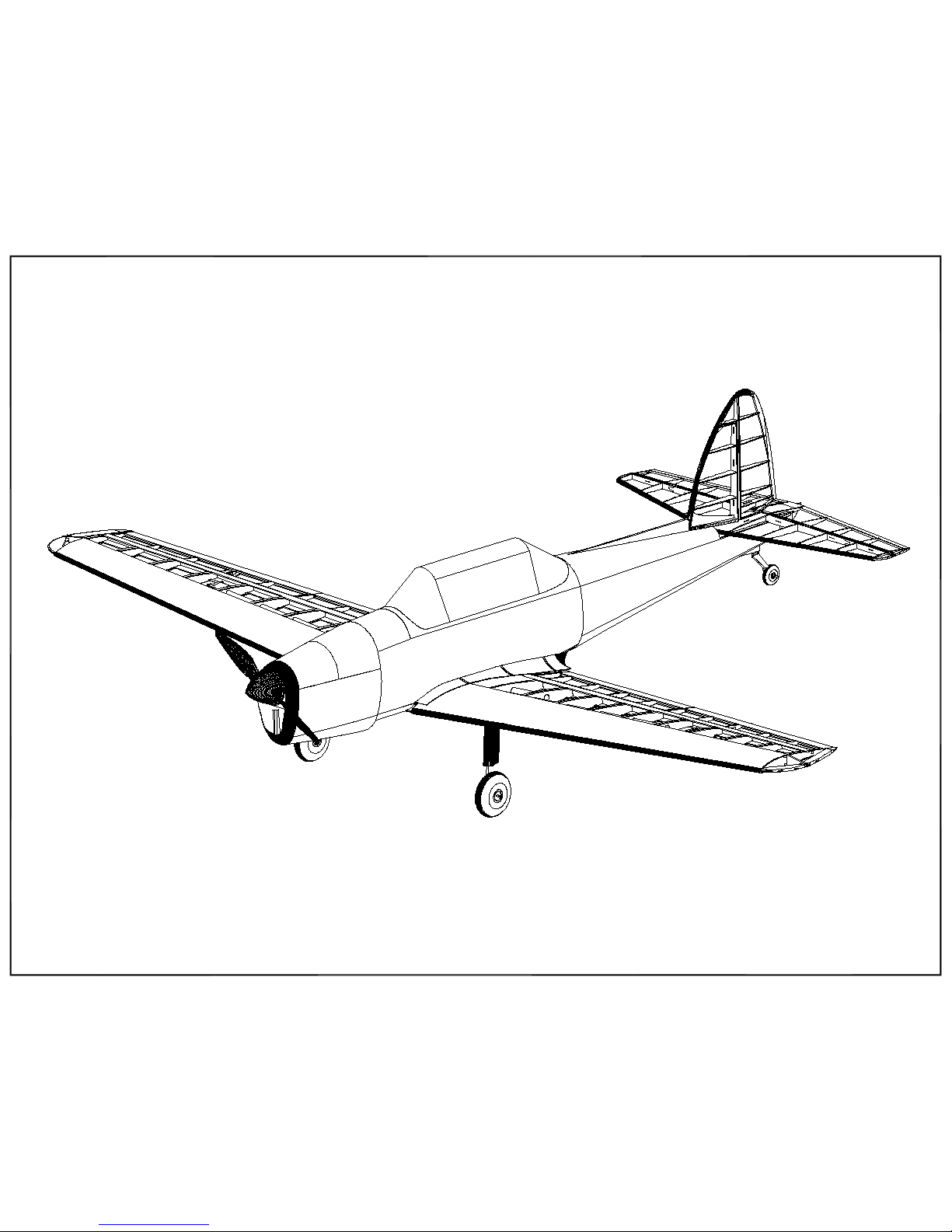
deHavilland DHC-1 Chipmunk
Assembly Guide
Manzano Laser Works

The Manzano de Havilland DHC-1 Chipmunk is based on a design developed by Ivan
Pettigrew. The structural design has been updated to take advantage of laser cut parts and to
help reduce the build time.
Construction of this model can be in any order preferred, but this assembly guide has been
organized to follow a suggested build sequence. That sequence begins with the tail surfaces
followed by the wing then the fuselage. This sequence is not critical but does facilitate
construction of the fuselage. Completion of the fuselage depends on having the wing and tail
surfaces available for shaping of some of the parts.
There are three 36” x 80” plan sheets for this model as follows:
Sheet 1 - Fuselage
Sheet 2 - Wing, Stab, Fin/Rudder
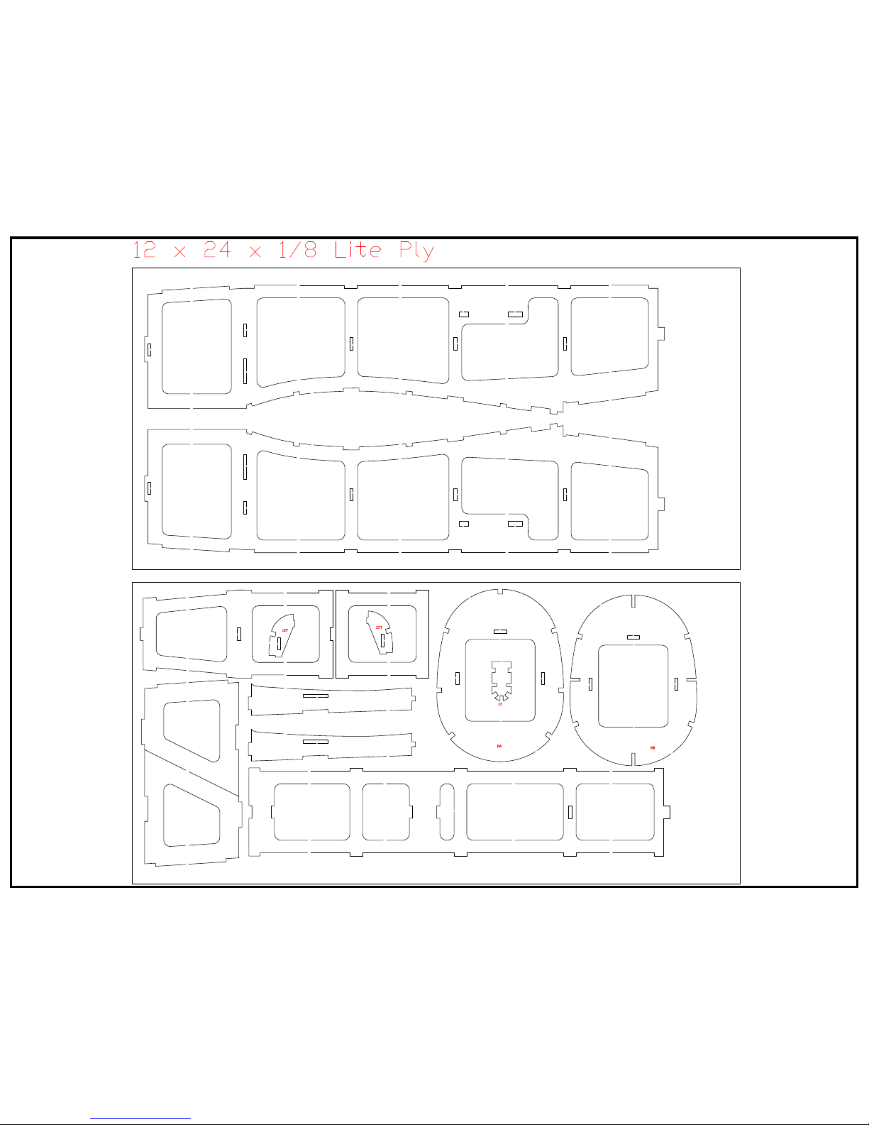
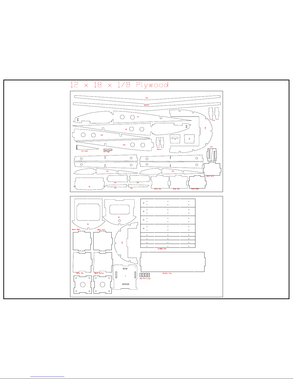
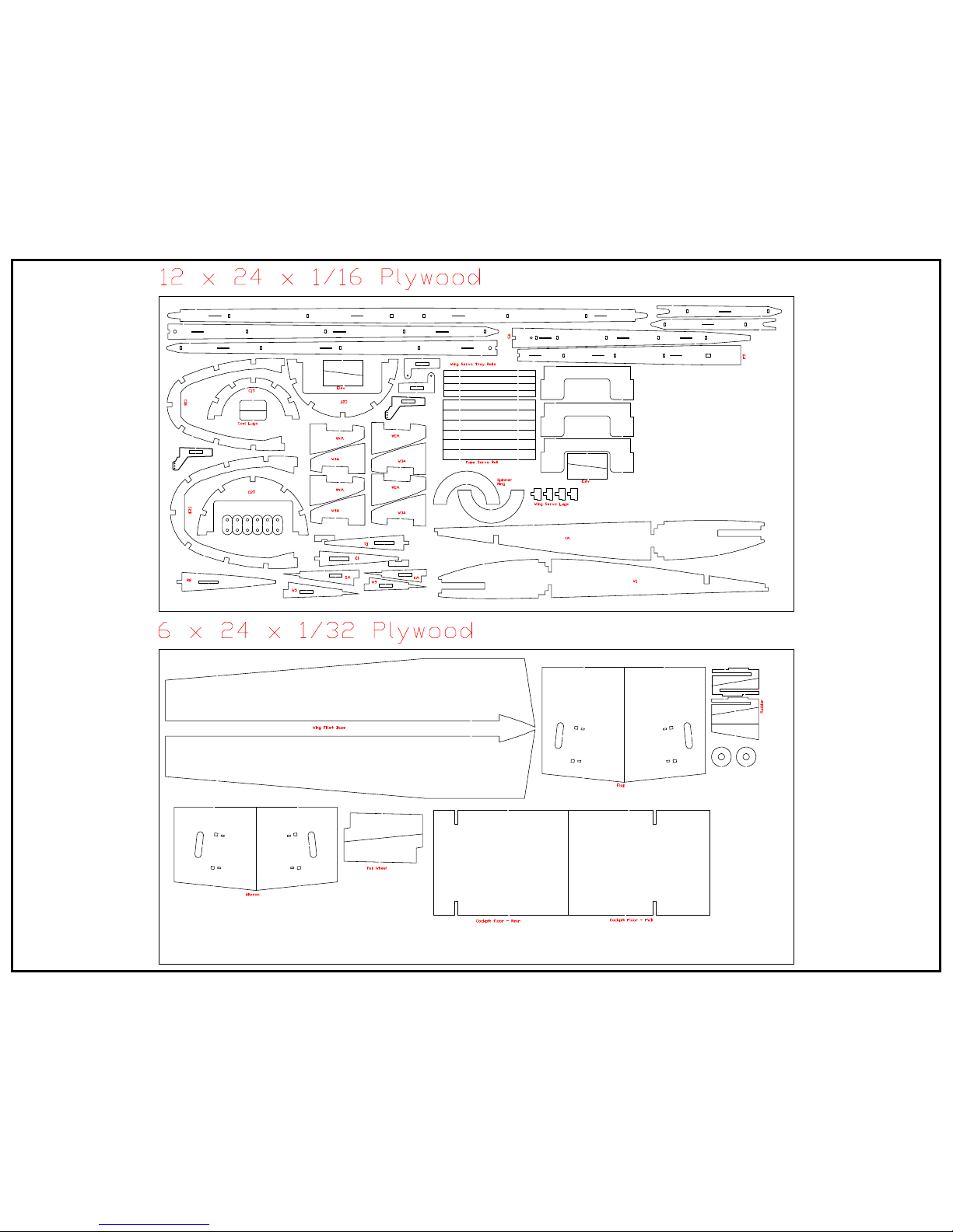
Sheet 3 - Sheeting and part layouts not included on the other plan sheets
Materials used in this model include balsa, liteply, plywood, brass tubing, and piano wire.A
formed plastic canopy is also used. Most of the wood and the formed canopy is supplied with
the kit. The builder supplies 3/16” and 1/8” square balsa strip stock, piano wire, brass tubing,
and the hardware needed to complete the model.
The completed model should have a flying weight in the 5 to 6 pound range. To provide a
reasonable power level for handling wind and take offs from rough terrain, a power loading of
at least 70 watts per pound is suggested. That translates to a motor/prop/battery selection that
can deliver at least 420 watts. The battery area of the model can accommodate up to four cell
lipo packs in the size range suitable for this model.


TAIL SURFACES ASSEMBLY
1.
Begin with the stab and elevators. Assembly begins by
laminating the spars. They are made up from a lamination of 1/8"
balsa and a lamination of 1/16" plywood.
Dry fit the stab ribs to the stab spar. Make sure the tabs on the
spar tips face down.The plywood laminations faces the r bs.
Place the assembly over the plan.
With the stab assembly lined up over the plan, dry fit the leading
edges to the r bs. They will lie flat on the rib tabs. The nose of
each rib fits in the leading edge notches. When everything is
properly aligned apply glue to all joints. Also glue the 1/8" balsa
joined to the center joint of the leading edge pieces.
2. 3.
4. 5. 6.
7. 8. 9.
Remove the stab assembly from the plan. The r b and spar tabs
can be removed at this time. The 1/16" balsa center section
sheeting will be installed during the final assembly steps.
Glue the stab tips to the assembly. The leading edge, tips, and the
back side of the spar can now be sanded to shape. Refer to the
plan cross section drawings for the shape of the spar back face.
The elevators are assembled using the same procedure as the
stab. Dry fit the r bs to the spars and then place on the plan. The
plywood side of the spars face the ribs. Add the trailing edge
pieces so the rear of each rib engages the notches. When
everything is lined up glue all of the joints.
Plywood boxes made from laminations of 1/32" plywood are used
to transfer the elevator control horn inputs to the elevator halves.
Glue the parts for each horn box and then install them in the
elevator halves. The tabs fit in elevator rib E1.
Remove the r b and spar tabs. Glue the elevator tips to the
assemblies. Sand the forward edge of each elevator half to the
profile shown on the plan cross section drawing. Sand the trailing
edge to a taper following the the rib top and bottom profile. Also
sand the elevator tips.
The fin and rudder assembly is very similar to the stab and
elevator halves. Begin by making up the fin and rudder spars.
They are laminated from 1/8" balsa and 1/16" plywood.
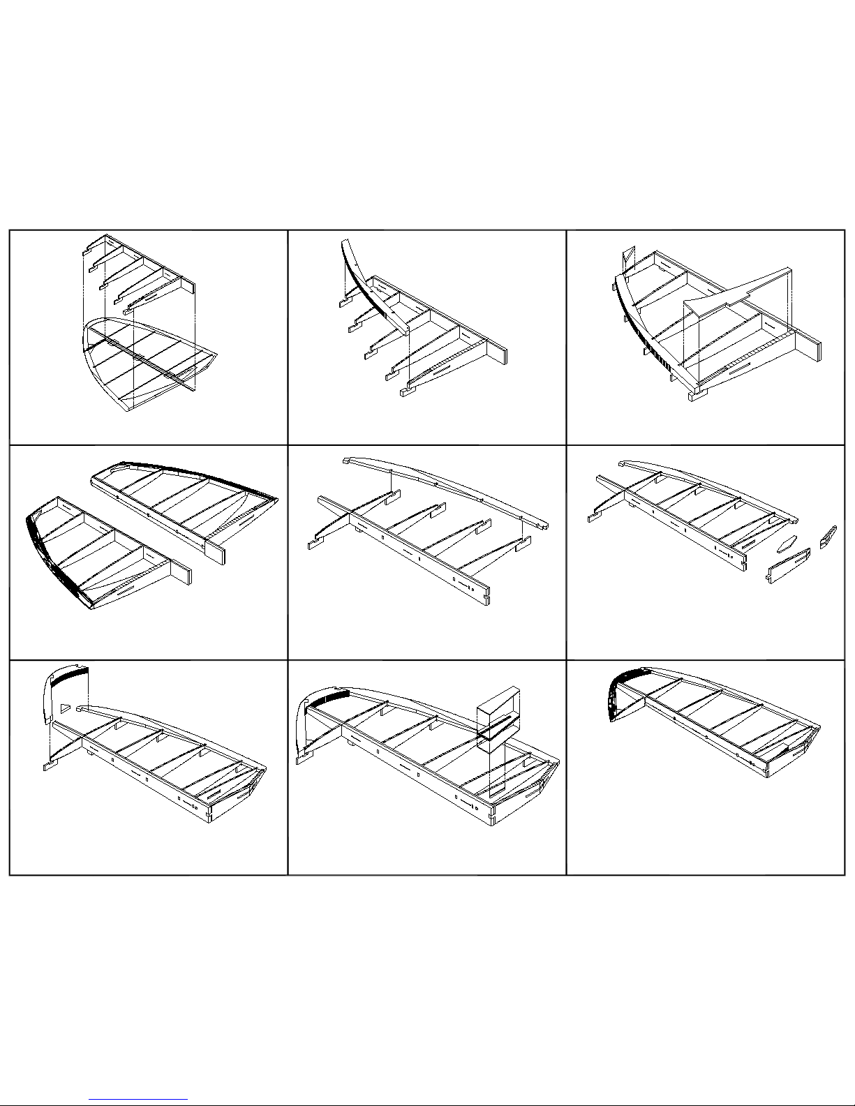
10.
Dry fit the fin ribs to the fin spar. Place the assembly over the
plan.
Glue the fin leading edge pieces F2 and F3 together. Place the fin
leading edge on the ribs making sure the nose of each rib is fully
seated in the notches. The leading edge will rest on the tabs. When
everything is lined up, glue all the joints. Glue the fin gusset to the assembly.
11. 12.
13. 14. 15.
16. 17. 18.
Remove the rib and spar tabs from the fin assembly. Shape the
leading edge and the rear spar face to the profile shown on the
plan cross section drawing.
Dry fit rudder r bs R9 through R12 to the rudder spar. Place over
the plan. Glue the rudder trailing edge parts R3 and R4 together.
Place the rudder trailing edge on the assembly. When every thing
is lined up glue the joints.
Dry fit rudder rib R8 to the assembly. Confirm the fit and alignment
and then apply glue to the joints. Make up rib R7 from the two
halves and the key. Sand a bevel on the forward face of the rear
half of R7 to match the plan profile. Glue the halves together using
the balsa key to align and strengthen the joint. Sand the forward
half of R7 to match the joint angle. Install R7.
Dry fit the rudder tip parts R1 and R2. When satisfied with the fit
glue the joint. Place the rudder tip on the assembly. R2 should be
centered on R3. When satisfied with the fit apply glue to the joints.
Also glue the gusset to the assembly.
The rudder horn box is made from 1/32" plywood laminations. The
core is three laminations. Build the rudder horn box and glue it to
rib R8 and the back face of the rudder spar.
Remove the r b and spar tabs. Sand the trailing edge to a taper
following the rib profiles. Shape the tip and sand the front face of
the spar to the profile shown on the plan cross section drawing.
This completes the assembly of the stab, elevator halves, fin, and
rudder. After they are covered CA hinges are use to mate the
surfaces. The balsa dorsal fin is shaped and installed on the model
during final assembly.
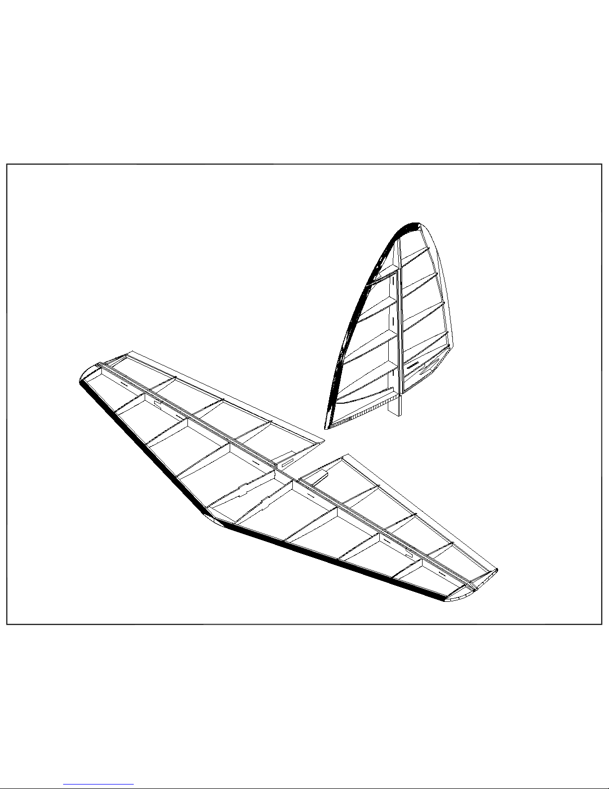
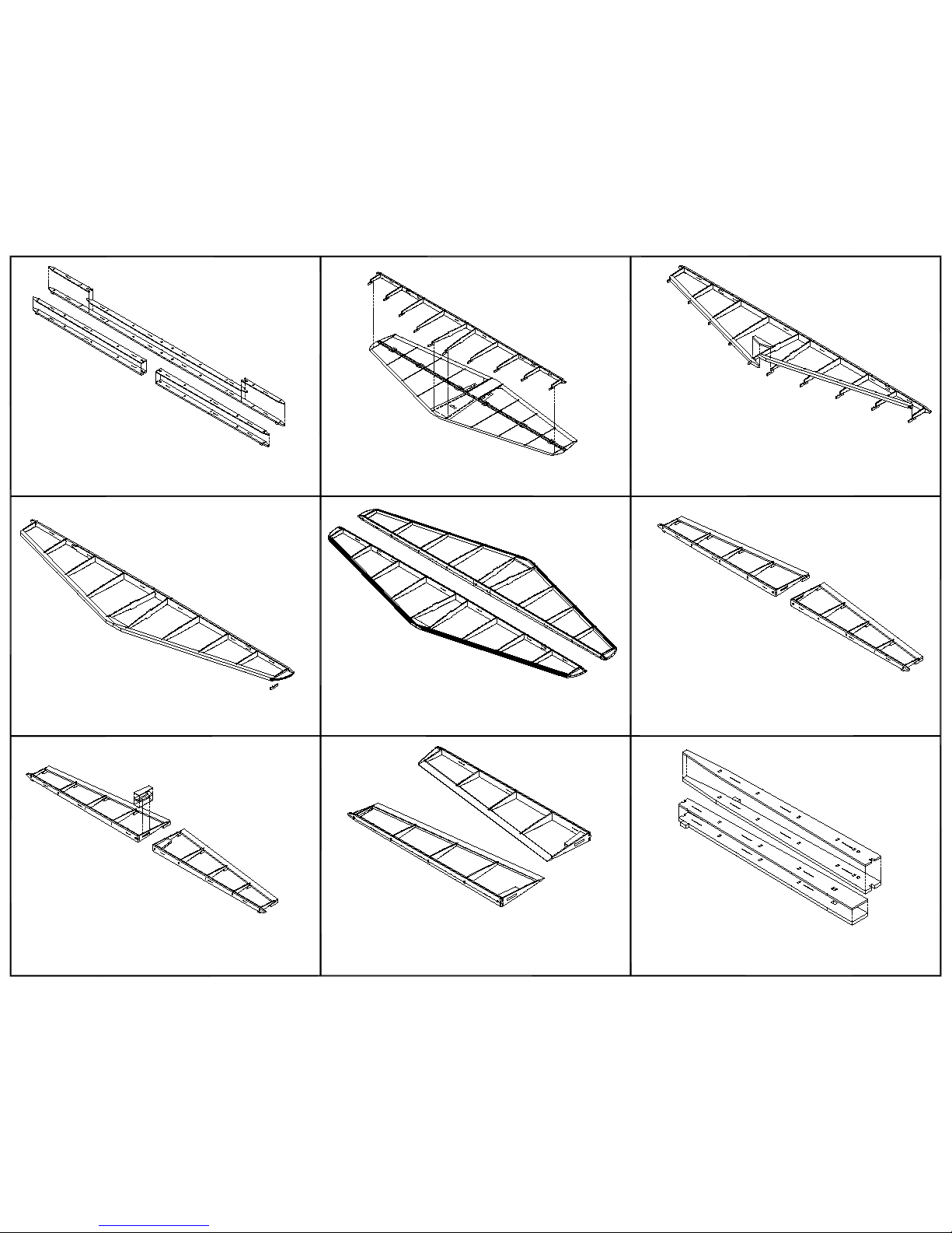
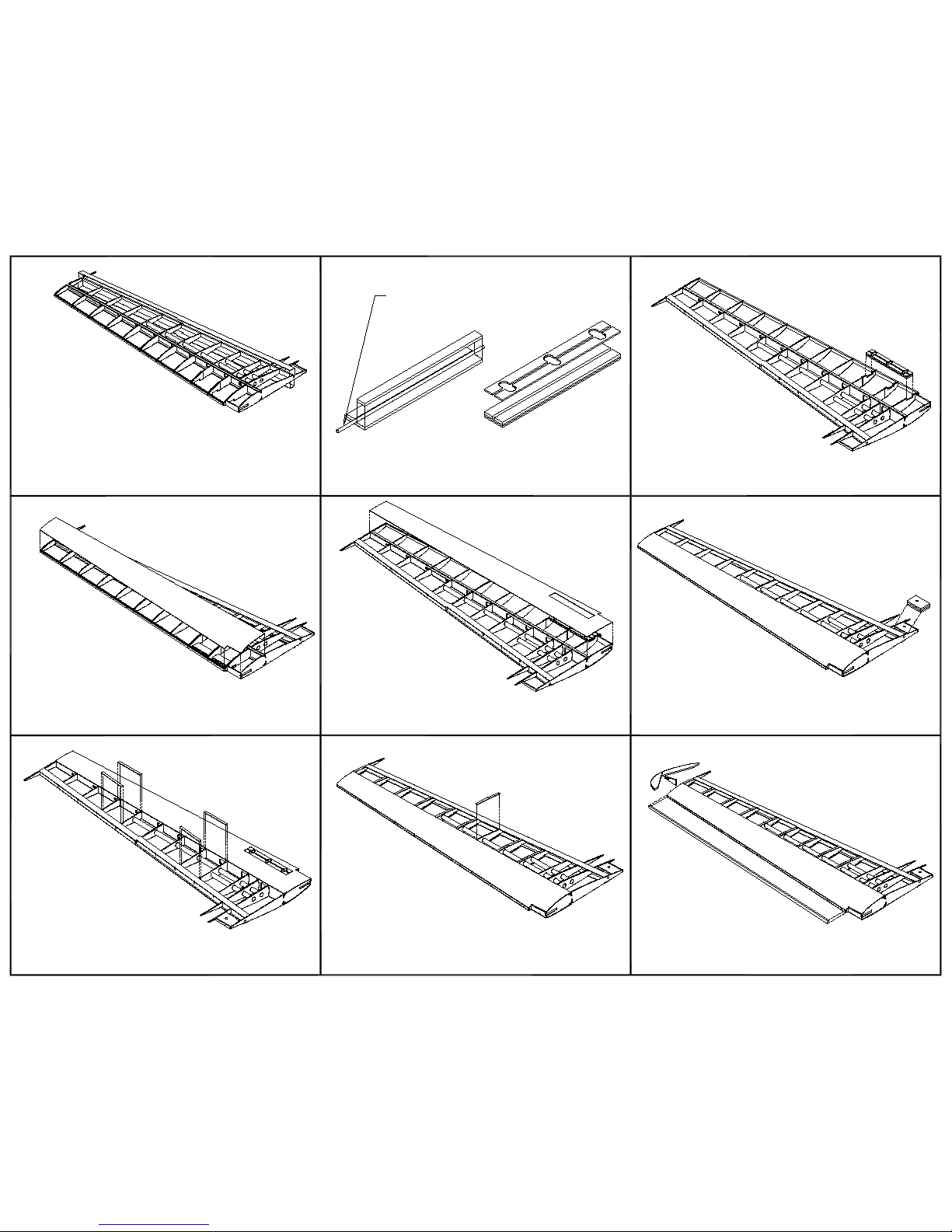
WING ASSEMBLY

1.
The wing assembly begins by laying a 36" strip of 1/8" square
balsa over one side of the wing plan in the location shown on the
plan. This strip generates the tip washout as the wing is built on
top.
Glue the 1/16" plywood doublers to ribs W3 and W4.
Layout one set of ribs W2 through W11 and one of the 1/8" balsa
sheet wing spars. Slide the ribs through their corresponding
openings in the spar and then twist them to be vertical. DO NOT
GLUE.
2. 3.
4. 5. 6.
7. 8. 9.
Fit the sub leading edge over the steps on the nose of each wing
rib. Make sure the sub LE is fully seated on each rib step. DO
NOT APPLY ANY GLUE YET.
Lay the UNGLUED assembly over the plan. Place r bs W2A and
W12. Slide the aileron and flap area trailing edge pieces on to the
rib steps making sure they are fully seated on each step. Again, DO
NOT glue anything yet.
Check the alignment of all the wing half parts relative to the plan.
Also make sure all of the ribs are touching the building surface and
the 1/8" square strip. A few straight pins can help make sure
everything stays in the proper place. Apply thin CA to all of the
joints.
Make up four paper tubes that are 1/2" in diameter. Allow for a bit
of overlap when rolling the tubes. Two of the tubes need to be 20"
long and the other two 7" long. Slide one of the long tubes into the
forward set of holes in the ribs. Slide a shorter tube into the other
set of wing r b holes. Apply a small amount of glue to each rib tube
interface.
Place rib W1 and parts W13 and W14. When satisfied with the fit
glue them in place. When the glue is set remove the assembly
from the building surface for the next step.
The 1/4" x 1/8" spar caps are now installed. It is recommended
that an air dry glue such as Elmer's Carpenter Glue or Titebond be
used. Apply some glue to the forward face of the spar where the
cap will go and to each rib notch. A.after the spar caps are in
place, lay the assembly on the plan over the washout strip to dry
W4
W3
Note that W7A and W7B are
together in the same spar slot
W13
W14
10.
Remove the structure from the building board. Sand the top and
bottom edges of the sub leading edge and trailing edges so they
match the contour of the ribs. Be careful not to sand the ribs.
Applying a strip of masking tape along the top and bottom of the
ribs just behind the sanding area is a good way to protect them.
Glue the trailing edge cap pieces to the wing. Make sure you use
the top piece on top.
Make up the two landing gear mounting blocks. They are made
from two laminations of 1/8" plywood with a 1/16" balsa face.
The balsa face can be sanded to match the bottom leading edge
sheeting.
Glue one of the landing gear mount blocks to the wing half. Use
the notches in r bs W2, W3, and W4. The hole goes toward the
wing root. Epoxy is recommended as the adhesive.
11. 12.
13. 14. 15.
16. 17. 18.
Cut and fit the top leading edge sheeting. Use an air dry glue l ke
Titebond for this step. Place the wing panel on the building board
over the plan when gluing the top leading edge sheeting in
place. This will help lock in the tip washout.
Remove the wing panel from the building surface. Cut and fit the
bottom leading edge sheeting. Glue it in place. Check to be sure
the tip washout has not been altered before the glue dries.
Glue the wing bolt reinforcement 1/4" balsa laminations together.
Fit and glue the filler block to the wing panel. Shape the filler
block to match the top and bottom r b contour.
Using 1/16" x 1/4" balsa strip stock, cut and glue a cap strip to the
top and bottom of wing ribs W4 through W12.
Install the 1/16" plywood servo tray rails in the flap servo rib bay
formed by W4 and W5, and the aileron servo bay formed by ribs
W8 and W9.
Install the leading edge piece. Next install the wing tip pieces.
Sand the leading edge and tip to their final shape.
Place a piece of 1/8" diameter piano wire next to
the first lamination before gluing the second
lamination. Remove the piano wire when both top
lamination pieces are in place.

Fit the bottom center section sheeting. Using the wing bolt holes
as a guide, from the top drill the bolt holes in the bottom sheeting.
19. 20.
21. 22. 23.
24. 25.
Make up each aileron and flap control horn assembly. Glue them
to the plywood rib in each aileron and flap. Also glue the balsa
pieces that provide a covering platform around the control horns to
the bottom of each assembly.
Build the ailerons and flaps over the plan. Dry fit the ribs to the
notched leading edge parts. Place the assemblies over the bottom
trailing edge pieces. Glue when aligned. Be sure to taper the rear
edge of the bottom trailing edge pieces. Note that the flap leading
edge is two pieces. Glue the forward piece to the assembly after
the other parts have been glued together.
Sand the leading edge of each aileron and flap assembly to the
profile shown on the cross sections provided on the wing sheet of
the plan set.
Also sand the wing trailing edge in the aileron area to the profile
shown by the plan wing cross sections.
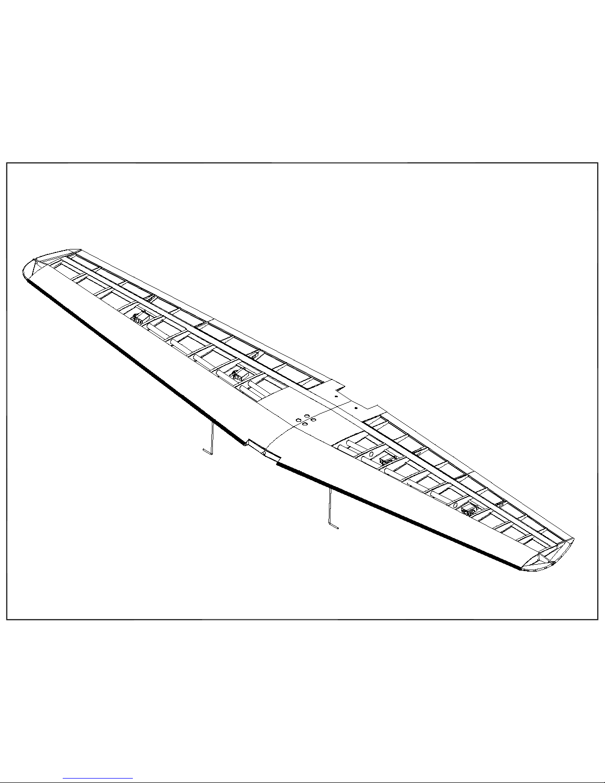
Build the second wing panel following steps 1 through 18 of this assembly guide section. The two wing panels are joined using two 1/8"
plywood doublers. Use epoxy to join the wing panels. Glue the center wing dowel to one wing panel before joining both panels. With one
wing panel laying flat on the building surface, the opposite tip should be 6" above the surface.
6" at the base of W12
Fit the top center section sheeting. Sand a taper at the rear of the
rearward piece to mate with the bottom sheeting. Using the wing
bolt holes as a guide, from the bottom drill the bolt holes in the top
sheeting.
Taper
Taper
Aileron
Flap
Add pieces of 3/16 balsa to the back face of the flap leading edge and wing trailing edge where the flap hinges will be installed. Refer to
the plan for this step. Robart hinge points are used for the flap hinges. Refer to the wing plan cross section drawings to see the proper
orientation of the hinge points. Drill the flaps and wing trailing edge for the hinge points. Dry fit the flaps to the wing. Make sure they will
rotate down freely and then remove them and the hinge points from the wing.

26. 27.
This completes the wing structural assembly. The ailerons and flaps are installed after they and the wing are covered. Make sure the flaps still rotate down freely after the hinge points have been
glued. CA hinges are used for the ailerons.
After the ailerons and flaps have been installed, mount servos to the servo trays. Servo extenson leads will be necessary for the servos.
Route the servo leads through the servo lead tubes starting from the servo bays. Pull the connectors through the appropriate holes in the center section top sheeting.
Mount the servo trays using four wood screws in the corners of the trays.
28.
29.
Bend the landing gear legs using 1/8" diamater piano wire.
Place the landing gear legs into the slots of the landing gear
mounting blocks. Place a plywood retaining lug in the pockets of
the mount block. Mark the location of the retaining screws. After all
of the screw locations have been marked, dirll pilot holes for the
screws. Run screws into each hole.
Make up the four servo trays using the 1/32" plywood and 1/16"
balsa tray laminations. The flap and aileorn trays are different in
size so be sure to match the appropriate part pairs. Set the
laminations so there will be a right and left tray. The balsa
lamination faces the outside of the wing. The servo mounting lugs
are the same for all four trays.

FUSELAGE ASSEMBLY

1.
Fuselage assembly begins with the internal liteply box.
Assemble the sides, top pieces, and formers 3B, 4B, and 7B.
Dry fit all the parts before adding any glue.
Add the bottom internal box piece that fits behind 7B. Install the top, side, forward, and rear formers. These are a
combination of balsa, plywood, and liteply parts.
2. 3.
4. 5. 6.
7. 8. 9.
Install the battery pack tray. Place one tabbed end in the notch
of 4B and then rotate the other end down so the tab fits in the
the notch in the bottom of the forward bulkhead.
Install 3/16" square balsa stringers in the slots of the formers. The
outer edges of top formers 3T,4T, 4C, 5T, and 6T are glued to the
stringers that run parallel to the top of the internal liteply box.
Install parts 4S and 7S on each side of the fuselage in the
locations shown. The bottom edge of each part is flush with the
top of the notches in the wing saddle area next to side formers 4
and 7. The parts should be on the wing saddle side of each side
former.
4S
7S
Assemble the two sets of wing saddle parts WS1 through WS3.
The wing saddles are then glued to the fuselage internal box and
the bottom of the side formers. The tabs on the wing saddles fit in
the notches of the liteply box sides. The bottom of formers 5 and 6
along with pieces 4S and 7S match the dihedral angle.
Assemble the motor mount. The mount is set up so the length can
be adjusted for the motor being used. The inner box can slide fore
and aft in the outer box. DO NOT GLUE the inner box in the outer
box until it is time to install the motor. Please note that the inner
box sets the right thrust. Make sure the top and bottom pieces
have the same orientation relative to the slanted faces.
Glue the motor mount outer box to the forward fuselage bu khead.
The tabs of the motor mount box fit in the corresponding slots in
the nose former.
WS1
WS2
WS3
Other Manzano Laser Works Toy manuals


 Assembly manual")


