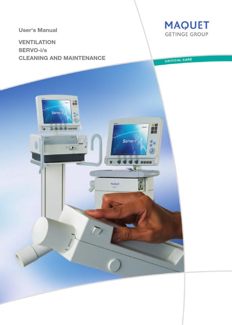
Maquet Servo ventilator 900 C User manual

Service Manual
SERVO VENTILATOR 900 C/D/E

2
Contents
Introduction . . . . . . . . . . . . . . . . . . 4
Principle diagram. . . . . . . . . . . . . . . . 6
Pneumatic unit
Gas flow through the ventilator . . . . . . . . . 8
Gas supply . . . . . . . . . . . . . . . . . 9
Bellows and spring assembly. . . . . . . . . . 10
Gas supply unit . . . . . . . . . . . . . . . 11
O
2cell . . . . . . . . . . . . . . . . . . . 12
Relief/safety valve and working
pressure manometer . . . . . . . . . . . . . 12
Flow transducer . . . . . . . . . . . . . . . 14
Pressure transducer . . . . . . . . . . . . . 15
Inspiratory valve and step motor . . . . . . . . 16
Expiratory valve and pull magnet . . . . . . . . 17
Non-return valve . . . . . . . . . . . . . . . 17
Transducer interface . . . . . . . . . . . . . . 18
Electronic unit
Principle of operation . . . . . . . . . . . . . 19
Reference level generation . . . . . . . . . . . 20
Regulation of inspiration. . . . . . . . . . . . 23
Timing. . . . . . . . . . . . . . . . . . . 28
Monitoring . . . . . . . . . . . . . . . . . 33
Regulation of expiration . . . . . . . . . . . . 39
Voltage supply . . . . . . . . . . . . . . . 41
Input/output . . . . . . . . . . . . . . . . 42
Disassembling
Disassembling the pneumatic unit . . . . . . . . 44
Disassembling the electronic unit. . . . . . . . . 44
Replacement of step motor assembly
and pull magnet . . . . . . . . . . . . . . . 45
Replacem
ent o
f power supply unit . . . . . . . 45
Replacement of safety catches . . . . . . . . . 45
Replacement of flow transducer . . . . . . . . 46
Adjustments
Adjustment of meters Z1 and Z2 . . . . . . . . 46
Adjustment of valve arm. . . . . . . . . . . . 46
Replacement and adjustment of R5 . . . . . . . 47
Removing the front panel knobs . . . . . . . . 47
Front panel potentiometer adjustments. . . . . .
48
Troubleshooting . . . . . . . . . . . . . . . . 49
Index . . . . . . . . . . . . . . . . . . . . 52
Block diagram . . . . . . . . . . . . . . . . . 56
Contents
To the responsible service personnel
The contents of this document are not binding.
If any significant difference is found between
the product and this document, please contact
MAQUET for further information.
We reserve the right to modify products without
amending this document or advising the user.
We recommend using MAQUET authorized
personnel for all service and repairs and the
use of MAQUET exchange parts or genuine
spare parts. MAQUET will not otherwise assume
responsibility for the materials used, the work
performed or any possible consequences of
same.
The Servo Ventilator 900 was orginally
manufactured and sold by Siemens. Responsibility
for the product was assumed by MAQUET Critical
Care in 2003. Manufacturing of the product was
discontinued in 2004.
Please note that this Service Manual has only
been re-labeled from Siemens to MAQUET. No
further significant changes are made. Thus,
some information in the Service Manual may be
outdated.
In case of questions, please contact your local
MAQUET representative
Your local MAQUET representative supplies factory
calibrated and tested plug-in circuit boards as well
as other spare parts indicated in the spare parts
list. When exchanging spare parts, always state
serial number of the apparatus and fault-symptom.
Note that the Operating Manual is an indis-
pensable complement to the Service Manual for
proper servicing.
About this manual
This Service Manual is intended for Servo Ventilator 900 C,
D and E. When reading the manual, please note:
SV 900 C SV 900 D SV 900 E
Read all
information
Do not read
information out-
lined in red
Do not read
information in
shaded areas

3
Product information program
This Service Manual is a part of a comprehensive in-
formation program for Servo Ventilator 900 C/D/E.
The program is planned to contain the following:
Promotional and Scientific Publications
Operating and Service Instructions
Product Training Material
Brochure Servo Ventilator
Concept
Application
Brochures:
Intensive Care,
Anesthesia,
Transportation
Operating
Manual
Brief Operating
Instructions
Training
Instructions
Front Panel
Flip-chart
Advisory
Booklet for
Instructors
Panel Block
Wall Diagram
for Cleaning
Slide Series
including
Textbook
Trainee’s Set
Product Leaflet
“I am breathing
through a
ventilator”
Film and
Booklet
Video
programs,
Video guide,
Video news
Reprints
Circuit Diagram
The Patient’s
ABSee@
Cards and
Poster
Service Manual

4
Introduction
Principle of operation
The Servo Ventilator 900 C/D/E consists of two sepa-
rate units.
The pneumatic unit comprises the gas conduction
system with two pressure transducers, two flow
transducers and two servo valves.
Each transducer, continuously delivers its actual value
to the electronic unit.
The servo valves are used as CONTROLLING
ELEMENTS for the control of inspiratory and expiratory
gas conduction.
The electronic unit comprises three controlling
systems, two for regulation of inspiration and one for
regulation of expiration.
The three controlling systems will be in use, one at a
time, depending on the TIMING control and the selected
ventilation MODE.
Pneumatic unit
Electronic unit SV 900 C
Electronic unit SV 900 D
Electronic unit SV 900 E

5
Introduction
Feedback control
(= regulation system)
Each of the controlling systems comprises its PID-
controller, (P=Proportional action, I=Integral action and
D=Derivative action), as shown in the picture.
The CONTROLLING ELEMENT will be positioned by
the PID-CONTROLLER (output).
P-action gives a continuous basic positioning.
(Thereby the ACTUAL VALUE will correspond to the
DESIRED VALUE).
I-action gives a slowly varying positioning com-
pensation for small long time error (in the ACTUAL
VALUE).
D-action gives a speed-up positioning reaction at fast
changes (in the ACTUAL VALUE).
The actual value from the TRANSDUCER in use is
compared with the desired value from REFERENCE
LEVEL. The difference between the ACTUAL VALUE
and the DESIRED VALUE results in an ERROR SIGNAL,
which is converted to a positioning signal for the
CONTROLLING ELEMENT (inspiratory and expiratory
valve respectively). The valve in use will then be moved
into such a position that the error will be corrected. In this
way, the desired value is maintained independently of
changes in the airways and the lungs.

6
!
Reference level
The main block REFERENCE LEVEL generates the
DESIRED VALUE for each regulating system, corre-
sponding to the settings on the front panel.
@
Regulation of inspiration
The regulation of inspiration is done by means of the FLOW
SERVO LOOP in the following modes: VOL. CONTR. VOL.
CONTR. + SIGH. MAN., each mandatory inspiration during
SIMV + PRESS. SUPPORT and each mandatory inspiration
during SIMV.
The actual value for the controller in this loop comes
from the FLOW TRANSDUCER in the inspiratory channel.
The regulation of inspiration is done by means of the
PRESSURE SERVO LOOP in the following modes: PRESS
SUPPORT. PRESS. CONTR., CPAP, each spontaneous
inspiration during SIMV + PRESS.SUPPORT and each
spontaneous inspiration during SIMV.
The actual value for the controller in this loop comes
from the PRESSURE TRANSDUCER in the inspiratory
channel.
The ERROR SIGNAL from the controller in use (flow
or pressure), is fed to a converter, common to both
inspiratory servo loops, which delivers the valve
control signal to the inspiratory valve (positioning).
For both servo loops, the inspiratory valve is the
controlling element in regulation of inspiration.
#
Timing
Reference timing pulses (START SIMV CYCLE, CLOCK,
INSP.TIME and EXP.TIME) are generated in this main block.
The TIMING gets some command variables from the
front panel settings.
$
Monitoring
The monitoring of all values that are displayed on the panel
meters and the digital display takes place in this main
block.
Some of the readings are compared with preset alarm
limits and visual and audible alarms are activated if the
preset limits are exceeded.
The monitoring system is independent of the
regulating systems.
The pressure limiting system is included in this
main block.
%
Regulation of expiration
The regulation of expiration is done by means of the
PRESSURE SERVO LOOP during expiration in all modes
when using PEEP.
The actual value for the controller in this loop comes
from the PRESSURE TRANSDUCER in the expiratory
channel.
The error signal from the controller is fed to a con-
verter which delivers the valve control signals for the
expiratory valve (positioning).
The expiratory valve is the controlling element in
regulation of expiration.
^
Power supply
The four regulated supply voltages are; +5V, ±15V and
+24V.
&
Input/output
Output signals are buffered in this main block.
Some of the functions of the ventilator can be
externally controlled via inputs in this block.
= Not valid for SV 900 D = Not valid for SV 900 E
Principle diagram

7
Principle diagram
= Not valid for SV 900 E
= Not valid for SV 900 D
!@
#
$%
^
&

8
Pneumatic unit
The flap valve prevents
back flow of gases in
the expiratory tubing.
It is essential for the
trig function
The working pressure is
mechanically adjusted
Gas flow through the ventilator
The gas flow to the patient
is measured
The safety valve opens if the
bellows is overfilled or if the
pressure in the bellows exceeds
approximately 120 cm H
2
O
The airway pressure is measured
The gas conduction from the
patient is regulated
From patient
The gas flow from the
patient is measured
To patient
The gas is filtered
O
2
concentration in the gas is
measured
The gas supply is regulated so
that a constant filling volume is
maintained in the bellows
Gas inlets
A more detailed description of the pneumatic
unit is found in the Training Instructions
The working pressure is shown
on a manometer
The gas conduction to the patient
is regulated

9
Gas supply
The lower gas inlet is used for high pressure gases 250-
700 kPa). The inlet can be connected either via a gas mixer
or directly to the hospital central gas supply, to gas bottles
or to a compressor.
The upper gas inlet is used for low pressure gases,
e.g. from an anesthesia circuit or a flowmeter. Normally,
only one of the two inlets is used at a time.
In any case, the gases pass a one-way valve, an
O2cell and a bacteria filter. The bacteria filter removes
99.998% of all particles down to a size of 0.3 microns.
When an anesthesia vaporizer is used, the gas supply
unit has a different construction with three nipples. For
further information, see the Operating Manual for the
vaporizers.
When the gas is supplied via the high pressure inlet,
a constant filling volume is obtained in the bellows by
means of the gas inlet regulatory function of a controlled
inlet valve. A constant working pressure is obtained by
the action of the spring assembly.
Pneumatic unit

10
Pneumatic unit
Bellows and spring assembly
The bellows are placed in a double coil spring set between
two metal plates. The lower plate is movable and spring
tensioned. The upper plate acts as a lid, which is firmly
positioned above the bellows.
A double coil spring set is arranged to give a constant
pressure to the bellows, independent of the plate position.
The pressure is set by the adjustment handle PRESET
WORKING PRESSURE.
Coil springs

11
Pneumatic unit
Gas supply unit
The gas supply unit contains an on-demand valve for the
high pressure gas, a controlled inlet valve, two one-way
valves, the O2cell holder and a bacteria filter.
Normally, the high pressure inlet is used and the
bellows are filled through the controlled inlet valve, a one-
way valve and the bacteria filter.
Mechanically actuated gas supply unit
The pressure plate acts upon the controlled inlet valve
via the lever arm. Before connecting the gas supply, the
bellows are empty, the pressure plate in top position and
the controlled inlet valve open. When connecting high
pressure gas, the bellows fills, the actuating tab on the
right edge of the pressure plate goes down against the
lever arm until the controlled inlet valve has closed. The
pressure plate is then in its regulating position, which
means that during inspiration, gas is continuously fed to
the bellows. Thus a constant gas volume is kept in the
bellows when using the high pressure inlet.
When a constant gas flow (from a flowmeter) is
supplied via the low pressure inlet, excess gas will be let
out from the bellows by the relief valve (surplus function).
Gas supply unit for Vaporizer with magnets
When using Vaporizer 950, 951 or 952, a gas supply
unit with three gas inlets has to be used and the
actuating tab on the pressure plate must be replace by
a magnet kit.
Electronic gas supply unit for vaporizer
The gas is normally supplied via a gas mixer at the
lower gas inlet. This inlet is controlled by a 24 V
electromagnetic inlet valve.
The built-in PC-board has two Hall-sensors,
sensing the position of the pressure plate magnet.
When the magnet reaches up to the upper Hall-
sensor, the inlet valve will open. When the magnet
reaches down to the lower Hall-sensor, the inlet valve
will close.
Also when there is no power, the inlet valve is kept
closed.
= Not valid for SV 900 E

12
Pneumatic unit
O2cell
The O2cell used in the ventilator gives an output voltage
proportional to the partial pressure of O2at the cell. At
constant sum of barometric pressure and WORKING
PRESSURE (and constant temperature), the output voltage
is proportional to the relative O2CONCENTRATION.
For each O2cell, the variable output will stay at
a fairly constant level during the life time of the cell
(approximately 800 000 %xhours).
The output voltage level from the cell is usually within
7-15 mV in normal air.
Relief/safety valve and working
pressure manometer
The working pressure manometer is connected to the
safety valve via a plastic tube. A bacteria filter protects the
manometer from contamination.

13
Safety function
Pneumatic unit
Relief/safety valve for gas
evacuation
A special reief/safety valve has to be used for gas
evacuation.
For detalíls, see corresponding Operating Manual.
The relief/safety valve may be opened in two ways. Firstly,
if the bellows tend to overfill, a metal rod will push the lever
to let out excess volume (surplus function). Secondly, if the
working pressure exceeds approximately 120 cm H2O, the
valve will let out excess pressure (safety function).
= Not valid for SV 900 E

14
Pneumatic unit
Flow transducer
The inspiratory and expiratory flow transducers have
the same construction. The gas flows through the flow
transducer in two parallel channels, one large main
channel, and one small measuring channel.
The main channel is fitted with a wire mesh net, the
resistance of which causes a certain proportion of the
gas to flow through the measuring channel.
The flow through, and the differential pressure
across, the measuring channel acts on a small metal
disc (“flag”), which, via a metal pin presses on a small
semiconductor strain gauge. This consists of diffused
resistors on both sides of an elastic silicone rod. The
resistors are connected as a part of a Wheatstone bridge,
the other part of which is situated on the TRANSDUCER
INTERFACE board (PC 765).
The more flow in the channel, the higher the pres-
sure on the strain gauge. The change in resistance in
the Wheatstone bridge, is converted to a corresponding
signal voltage.
The output signal from the flow preamplifier is a non-
linear function of the flow. The flow preamplifier signals
are linearized on PC board 5 (inspiration) and on PC
board 4 (expiration), respectively.
A resistor, 220 Ohms, 6W, is moulded into the
transducer and is used for heating of the expiratory flow
transducer. The transducer is heated to approximately
60°C (140°F) to prevent condensation of water vapour.
The inspiratory flow transducer has the same resistor,
but since it is not connected to any voltage, it will not be
heated.
If water should condense in the expiratory flow
transducer, the resistance of the wire mesh net increases.
Thus the output signal will increase. This can be seen on
the meter EXPIRED MINUTE VOLUME, or on the digital
display, as an increased reading. The accumulation of
medicaments, mucus and secretions in the expiratory
flow transducer gives the same result.
For details on cleaning and calibration of the flow
transducer, see the chapters Routine cleaning and
Calibration in the Operating Manual.

15
Pneumatic unit
Pressure transducer
The pressure transducers in the inspiratory and expiratory
channels are of the same type.
The gas pressure acts upon a silicone rubber mem-
brane into which is moulded a strain gauge of the
same type as in the flow transducers. The strain gauge
resistors are connected as a part of a Wheatstone bridge,
the other part of which is situated on the TRANSDUCER
INTERFACE board (PC 765).
The output signal voltage from the pressure amplifier
is proportional to the gas pressure.
When replacing the pressure transducers, the
preamplifier zero and gain have to be adjusted. For
details, see the chapter Calibration in the Operating
Manual.
Each pressure transducer is connected to its channel
via a plastic tube and a bacteria filter. The bacteria filter
and the plastic tube for the inspiratory channel should be
replaced after every 1000 hours of operation.
The bacteria filter and the plastic tube for the ex-
piratory channel should be replaced after every patient.

16
Pneumatic unit
Inspiratory valve and step
motor
The inspiratory valve is operated by the step motor via the
logarithmically slotted cam and the lever arm.
When the step motor is in operation, a ball bearing at
the end of the lever arm travels in the slot.
The lever arm squeezes the inspiratory valve
tube against a fixed arm. The change in the flow is
approximately 10% for each step of the step motor,
independent of the motor position as long as the airway
pressure is unchanged.
The step motor has four coils which are fed with
positioning signals from PC board 6 in the electronic unit.
When the mains voltage is switched off (or at mains
voltage failure) the step motor will always end up with the
inspiratory valve in fully opened position.
The maximum speed of the step motor is about 480
steps/second and the time elapsing from fully open to
fully closed position is approximately 0.1 second.
The plastic case contains two PC boards, one with
two miniature lamps and the other with two photo
detectors. When the step motor reaches either end
position of the cam slot, the light beam between the lamp
and the photo detector is interrupted by the cam screen.
This will generate an end position signal for the electronic
circuits on PC board 6.
The position of the lamps in relation to the screen is of
the utmost importance. If the lamps by any chance come
out of position, this will cause the step motor to “rattle”
because end positions are not properly indicated. The
same symptom occurs if a lamp is damaged.

17
Pneumatic unit
Expiratory valve and pull
magnet
The expiratory valve comprises a pull magnet acting on
a lever arm which squeezes a silicone rubber valve tube
against a fixed arm. The valve will close when the magnet
is activated. When the supply current to the magnet is
removed, the valve will open fully because of the spring.
This ensures that the patient can always exhale through
the ventilator at voltage failure.
The expiratory valve is controlled by the signals from
the electronic unit. At a PEEP setting, the information
from the pressure transducer in the expiratory channel
regulates the valve position during expiration.
Non-return valve
The purpose of the flap valve is to prevent air from entering
the patient circuit through the expiratory channel.
The valve is a vital part of the triggering function
since a patient trig is sensed in the expiratory channel
(pressure drop).
➡

18
This PC board comprises the preamplifiers for INSP. FLOW
and EXP. FLOW, the amplifiers for AIRWAY PRESSURE (I),
AIRWAY PRESSURE (E) and O2CONCENTRATION.
The INSP.FLOW WORKING POINT INDICATOR,
EXP.FLOW WORKING POINT INDICATOR and the 6.8V
REGULATOR and its 6.8V REGULATOR MONITOR are
also included on this PC board.
The CALIBRATION POTENTIOMETERS and the
CALIBRATION SWITCH are situated on this PC board.
On failure in the 6.8V REGULATOR indicated by the
6.8V REGULATOR MONITOR block, the block AIRWAY
PRESSURE (I) AMPLIFIER will be influenced to generate
a high AIRWAY PRESSURE (I) signal which will result in
UPPER PRESSURE ALARM condition.
Transducer interface
(PC board no 11)
Pneumatic unit

19
The electronic unit contains the various electronic circuits
for regulation and monitoring. A general description is
found in chapter Introduction and the following chapter
comprises a detailed description of the PC boards
included in the electronic unit.
Electronic unit – Principle of operation

20
Electronic unit – Reference level generation
General
The front panel settings are converted to reference level
signals for the regulating systems.
This manual suits for next models
5
Table of contents
Other Maquet Fan manuals
Popular Fan manuals by other brands
S&P
S&P HR100V Homeowner's guide
Adler Europe
Adler Europe AD 7326 user manual

Home Decorators Collection
Home Decorators Collection HAVERBROOK AM634-PN Use and care guide
Hunter
Hunter Castleton 55043 Manual de instrucciones

Dimplex
Dimplex DCTF117NL instruction manual
Broan
Broan AI Series User's and installer's manual
