Marani DPA240P User manual

2 In - 4 Out Speaker Management System
DPA240P
2 In - 4 Out Speaker Management System

2 In - 4 Out Speaker Management System
DPA240P is a cost-effective 2-IN/4-OUT digital speaker management system. Designed to be catered for any
crossover configuration, it provides the suitable processing and control for live application use. It offers 2 analog
inputs,and 4 analog outputs, managed by a powerful DSP Engine, in addition to 24 Bit AD/DA Converters. Each
input channel provides a choice of EQ with a 5-band Parametric EQ, gain control, noise gate function and
configurable delay. Each output offers up to 5-band of parametric equalization in to the crossover filters which
themselves provide slopes from 6dB/Octave up to 48dB/Octave. Each output path also features peak limiter and
driver alignment delay. The DPA240P supports a full matrix mixing mode where inputs may be routed/mixed in any
ratio to any output. For remote configuration and control the DPA240P can be connected via USB or Rs485
connections. The control remote PC software allows simultaneous control up to 32 units, setting all parameters
and showing real time levels.
CAUTION
RISK OF ELECTRIC SHOCK
DO NOT OPEN
WARNING
TO REDUCE THE RISK OF FIRE OR ELECTRIC
SHOCK DO NOT EXPOSE THIS EQUIPMENT TO
RAIN OR MOISTURE
Introduction

Described below are the functions of the front panel control buttons and encoders for
the DPA240P.
•Getting Started
As soon as the DPA240P is turned ON the device model name will appear in the LCD screen:
and a status bar will show the progress of the DPA240P initialization process:
The DPA240P has three factory pre-set working modes:
After the initialization, the DPA240P will show on the LCD the first of the embedded preset
working modes, or the last one selected prior to the unit being turned off.
First time activation will default to the first of the preset working modes.
DPA240P
Speaker Management
1x2 WAY XOVER
DPA240P
DPA240P
2 In - 4 Out Speaker Management System
TipWizard
“1x2 Ways Xover” and
“4 Ways Xover”

Encoders and ENTER, ESC buttons
The DPA240P is equipped with 3 Relative Encoders, “NAV/PM1”, “PM2” and “PM3”, These
encoders allow you to navigate the user interface and edit sections of the processor. They allow
the user to navigate within the screen for the selection of sub-menus, pages and parameters and
to select the values to be assigned during the editing operations.
The “ENTER” and “ESC” buttons allow the user to confirm or NOT confirm the operations
performed by the encoders.
The UTILITY button allows the User to enter the Sub-menus and set the general characteristics of
the Processor. The A and B buttons allow the User to enter the Editing Menus of the Processor's
Input Channels and buttons 1, 2, 3 and 4, allow the User to enter the Editing Menus of the
Processor's Output Channels.
The A and B buttons as well as the 1, 2, 3 and 4 buttons have double functions dependent
on the push and hold time.
When the A and B buttons are pushed and held for more than one second Input Channels A or B
are either muted or unmuted. The red LED will illuminate when the Channel is muted. When the
“MUTE” LED is OFF, then the related Input Channel is UN-MUTED.
A momentary push of the A and B buttons enters the Editing Mode for the Input Channels (see
later for the Input Channel Editing details).
Th e blue “EDIT” LED will now be ON.
When the 1, 2, 3 and 4 b uttons are pushed and held for more than one second the Output
Channels 1, 2, 3 and 4 a re either muted or unmuted. The red LED will illuminate when the
Channel is muted. When the “MUTE” LED is OFF, then the related Output Channel is UN-MUTED.
A momentary push of the 1, 2, 3 and 4 buttons enters the Editing Menu for the Output
Channels (see later for the Output Channel Editing details). The blue “EDIT” LED will now be ON.
As stated above, the start-up default screen is the following factory preset:
From this point, sub-menus are accessed using the UTILITY”,“A/B”,“1/2/3/4”,“ENTER” and
“ESC” buttons and all parameters and values are navigated by the “NAV/PM1”,“PM2”and“PM3”
encoders. Please refer to the following menu structures:
2x3 WAY XOVER
DPA240P
2 In - 4 Out Speaker Management System
UTILITY, A/B and 1/2/3/4/5/6 buttons
DPA240P Menu and Sub-Menu Structures

MENU “UTILITY MENU” [Access by pushing the “UTILITY” button]
NAV/PM1 Encoder PM2 or PM3 Encoder
[to navigate between menus] [to chose option, then ENTER to load it;
(*) indicates the selected option]
1 UTILITY MENU:......
<< System Utilities >>
1.1 SYSTEM UTILITY: System Setup
<< System Setup >> Setup: 1x2 WAY XOVER
Setup: 4 WAY XOVER
1.2 SYSTEM UTILITY: Delay Units
<< Delay Units >> Unit: Time(ms) *
Unit: Distance (m)
1.3 SYSTEM UTILITY: Software Version
<< Software Version >> Version: V1.02 *
2 UTILITY MENU:......
<< Program Utilities >>
2.1 PROGRAM UTILITY: Recall a Program
<< Recall a Program >> 01: Preset 01
: :
48: Preset 48
2.2 PROGRAM UTILITY: Save a Program
<< Save a Program >> 01: Preset 01
: :
2.3 PROGRAM UTILITY: Delete a Program
<< Delete a Program >> 01: Preset 01
: :
3 UTILITY MENU:......
<< Interface Utilities >>
3.1 INTERFACE UTILITY: Interface Setup
Interface Setup Source: USB
Source: RS485 *
4 UTILITY MENU:......
<< Security Utilities >>
4.1 SECURITY UTILITY:Parameter will
Show Parameter be shown *
not be shown
4.2 SECURITY UTILITY: Lock Unit
Lock Unit Lock: Off *
Lock: On
4.3 SECURITY UTILITY:User Password
User Password [ ]
4.4 SECURITY UTILITY:Enable Password (For the details about the Password Setting/Enable
Enable Password Password: Enable and Unit Lock, , refer to the “ Utility Menus Use ”
Password: Disable * Section)
ENTER
ESC
ENTER
ESC
ENTER
ESC
ENTER
ESC
ENTER
ESC
ENTER
ESC
ENTER
ESC
ENTER
ESC
ENTER
ESC
ENTER
ESC
ENTER
ESC
ENTER
ESC
ENTER
ESC
ENTER
ESC
ENTER
ESC
ENTER
ESC
48: Preset 48
48: Preset 48
2 In - 4 Out Speaker Management System

MENU “Input A/B” Input Channels Editing [Access by pushing the “A/B” buttons]
NAV/PM1 Encoder NAV/PM1 Enc .PM2 Enc.PM3 Enc.
[to navigate between menus] [to chose values for the parameters, no need to confirm the chosen values,
which are automatically loaded during the encoders use]
3. Input A/B Gain
Gain = + 0.0 dB
-> Gain = + 0.0 dB PM1 N/A -15 db Same as Pm2
:
+15 dB
4. Input A/B Delay
Delay = 0.000 ms
-> Delay = 0.000 ms PM1 N/A 000.0000mS 000.0000mS
[1 ms steps] [20.8 us steps]
399.0000mS 000.9984mS
[Freq.] 20Hz [amp.] -----dB
: :
20kHz
ENTER
ESC
ENTER
ESC
1. Input A/B[Name] Name
Name=[Name]
-> Name = - (For Editing the Device's Name,refer to the Details on the "Utility Menus USE" Section)
ENTER
ESC
2. Input A/B[Name] NGate
Noise Gate=off
->Noise Gate=off/on
ENTER
ESC
5. Input A/B[Name] EQ Byp
EQ Bypass= off
->
ENTER
ESC
EQ Bypass= off PM1 N/A off
: Same as Pm2
6. Input A/B EQ-X(X from 1 to 5)
Bypass= off
->
ENTER
ESC
Bypass= off
on
Type=Y(Y= Peaking_Eq,Hi-Shelv_Q,Lo-Shelv_q,All Pass_2)
Type=Y
PM1 N/A off
: Peaking_Eq
on
:
Notch Filt
6.1 Input A/B EQ-X(X from 1 to 5)
Bypass= off
ENTER
ESC
6.1a. If selected a Peaking_Eq filter, then the filter can be set by
the following parameters
Input A/B EQ-[x] (up to 5 filters available)
[Freq] [Gain] [Q]
-> 1000Hz 0.0dB Q=1.00
6.1b. If selected a Hi-Shelv_Q (variable Q High Shelving) filter,
then the filter can be set by the following parameters
Input A/B EQ-[x] (up to 5 filters available)
[Freq] [Gain] [Q]
-> 1000Hz 0dB Q=1.00
6.1c. If selected a Lo-Shelv_Q (variable Q Low Shelving) filter,
then the filter can be set by the following parameters
Input A/B EQ-[x] (up to 5 filters available)
[Freq] [Gain] [Q]
-> 1000Hz 0dB Q=1.00
6.1d. If selected an All-Pass_2 (second order, variable Q All Pass) filter,
then the filter can be set by the following parameters
Input A/B EQ-[x] (up to 5 filters available)
[Freq] [Gain] [Q]
-> 1000Hz ----dB Q=1.00
-----dB
[Freq.] 20Hz [amp.] +12dB
: :
20kHz -12dB
[Freq.] 20Hz [amp.] +12dB
: :
20kHz -12dB
[Freq.] 20Hz [amp.] +12dB
[Q] 0.3
: : :
20kHz 20.00
-12dB
Through the PM2, it is possible to Byp the single selected filter.
Through the PM3, it is possible to select one of the 4 available
filters' type.
Once selected the filter Type and NOT in Byp mode, pressing
again the ENTER button can be accessed the selected filter's editing page.
[Q] 0.3
:
20.00
[Q] 0.3
:
20.00
[Q] 0.3
:
20.00
2 In - 4 Out Speaker Management System

MENU “1/2/3/4 Output Channels Editing” [Access by pushing the “1/2/3/4” buttons]
NAV/PM1 Encoder NAV/PM1 Enc .PM2 Enc.PM3 Enc.
[to navigate between menus] [to chose values for the parameters, no need to confirm the chosen values,
which are automatically loaded during the encoders use]
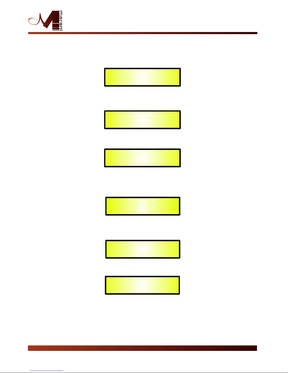
1. Out-[x] [Name] HPF
YF = 20.0 H (Y = Bypass OR Filter Type/Order, where filter type can be Buttw_1st, Buttw_2nd,
LRiley_2nd, Bessel_2nd, Buttw_3th, Buttw_4th, Lriley_4th, Bessel_4th,
Lriley_6th, Lriley_8th,)
-> YF = 20.0 Hz Freq Fast Selection [Filt Type] Bypass [Freq.] 20Hz
ONLY in Freq Editing Mode : :
Lriley_8th 20kHz
Through the PM2, it is possible to Bypass the filter or to select one of the 11 available
filters' type/orders, and through the PM3 to set the HP cutting Frequency (quick fine tuning by 1Hz steps).
Once selected the filter Type and pressing again the ENTER button can be accessed the selected
filter's Fast Freq.Selection page.
2. Out-[x] [Name] LPF
YF = 20.0 Hz (Y = Bypass OR Filter Type/Order, where filter type can be Buttw_1st, Buttw_2nd,
LRiley_2nd, Bessel_2nd, Buttw_3th, Buttw_4th, Lriley_4th, Bessel_4th,
Lriley_6th, Lriley_8th,)
-> YF = 20.0 Hz Freq Fast Selection [Filt Type] Bypass [Freq.] 20Hz
ONLY in Freq Editing Mode : :
Lriley_8th 20kHz
Through the PM2, it is possible to Bypass the filter or to select one of the 11 available
filters' type/orders, and through the PM3 to set the HP cutting Frequency (quick fine tuning by 1Hz steps).
Once selected the filter Type and pressing again the ENTER button can be accessed the selected
filter's Fast Freq.Selection page.
3. Out-[x] [Name] EQ Byp
EQ Bypass = Off
-> EQ Bypass = Off PM1 N/A Off Same as PM2
:
On
4. Out-[x] [Name] EQ-[x] (X from 1 to 5)
Byp = Off Type = Y (Y = Peaking_Eq, Hi-Shelv_Q, Lo-Shelv_Q, All Pass_2, )
-> Byp = Off Type = Y PM1 N/A Off Peaking_Eq
: :
On Notch Filt
Through the PM2, it is possible to Byp the single selected filter.
Through the PM3, it is possible to select one of the 4 available
filters' type.
Once selected the filter Type and NOT in Byp mode, pressing
again the ENTER button can be accessed the selected filter's editing page.
4.1 Out-[x] EQ-[x] (X from 1 to 5)
-> Byp = Off Type = Y
4.1a. If selected a Peaking_Eq filter, then the filter can be set by
the following parameters
Out-[x] EQ-[x] (up to 5 filters available)
[Freq] [Gain] [Q]
-> 1000Hz 0dB Q=1.00 [Freq.] 20Hz [Amp.] +12dB [Q] 0.30
: : :
20kHz -12dB 20.00
4.1d. If selected a Hi-Shelv_Q (variable Q High Shelving) filter,
then the filter can be set by the following parameters
Out-[x] EQ-[x] (up to 5 filters available)
[Freq] [Gain] [Q]
-> 1000Hz 0dB Q=1.00 [Freq.] 20Hz [Amp.] +12dB [Q] 0.30
: : :
20kHz -12dB 20.00
2 In - 4 Out Speaker Management System
ENTER
ESC
ENTER
ESC
ENTER
ESC
ENTER
ESC

4.1g. If selected a Lo-Shelv_Q (variable Q Low Shelving) filter,
then the filter can be set by the following parameters
Out-[x] EQ-[x] (up to 5 filters available)
[Freq] [Gain] [Q]
-> 1000Hz 0dB Q=1.00 [Freq.] 20Hz [Amp.] +12dB [Q] 0.30
: : :
20kHz -12dB 20.00
4.1q. If selected an All-Pass_2 (second order, variable Q All Pass) filter,
then the filter can be set by the following parameters
Out-[x] EQ-[x] (up to 5 filters available)
[Freq] [Gain] [Q]
-> 1000Hz ----dB Q=1.00 [Freq.] 20Hz [Amp.] ----dB [Q] 0.30
: : :
20kHz ----dB 20.00
5. Out-[x] [Name] Vu-Meter
Vu-Meter = Level
-> Vu-Meter = Level PM1 N/A Level Same as PM2
Limiter Act.
RMS Cmp Act.
6. Out-[x] [Name] Name
Name = [Name]
-> Name = _ (For Editing the Device's Name, refer to the Details on the“Utility Menus Use” Section)
7. Out-[x] [Name] Source
Source = InA
-> Source = InA PM1 N/A. InA (Channel A) Same as PM2
InB (Channel B)
InA+InB (Channel A+ Channel B)
8. Out-[x] [Name] Gain
Gain = + 0.0 dB
-> Gain = + 0.0 dB PM1 N/A -15 db Same as PM2
:
+15 dB
9. Out-[x] [Name] Limiter
A: 5ms R: 0.2s +16dB
-> A: 5ms R: 0.2s +16dB [Atk time] 5ms [Rel time] 0.1s [Amp.] -14.0 dB
: : :
200ms 3.0s +16dB
10. Out-[x] [Name] Delay
Delay = 0.000 ms
-> Delay = 0.000 ms PM1 N/A 000.0000mS 000.0000mS
[1 ms steps] [20.8 us steps]
399.0000mS 000.9984mS
11. Out-[x] [Name] Polarity
Polarity = Normal
-> Polarity = Normal PM1 N/A Normal Same as PM2
Invert
2 In - 4 Out Speaker Management System
ENTER
ESC
ENTER
ESC
ENTER
ESC
ENTER
ESC
ENTER
ESC
ENTER
ESC
ENTER
ESC

Menu “UTILITY” [access by pushing the “UTILITY” button]
From the “Default Screen”, it is possible access the“UTILITY”menu pushing the“UTILITY”button
and the Sub-Menus pages can be selected just rotating clockwise and counter-clockwise the
“NAV/PM1” encoder.
Once selected the sub-menu page, using the “ENTER” button can be accessed the Sub-Menus
pages, again “scrollable” using the “NAV/PM1” encoder and accessible for the parameters' editing
pushing again the “ENTER' button.
Through the “ESC” button, it is any time possible to go back to the action and page preceding the
“ENTER” button use.
Once inside the Sub-Menus pages, the several options can be scrolled and using the PM2 or PM3
encoders and selected/confirmed pushing the “ENTER” button.
Note : In every Sub-Menu the option currently selected/running will have an asterisk “ *
” showing
to the right of the description on the LCD screen.
Options that are not selected/running will be displayed with NO Asterisk.
Pushing the ENTER button on an unselected option will mean an asterisk will then appear and this
option will now take over as the currently selected/running option.
System Utilities Sub-menu
– this sub-menu allows to access several operations related to the
DPA240P Start Up and General Configuration:
From the “System Utilities Sub-menu”, pushing “ENTER”and then using the“NAV/PM1”encoder
for scrolling will give access to the following pages:
–System Setup: this page allows the selection of the operating mode of the DPA240P :
The operating mode can be chosen from a selection of 3 Xovers options :
2x2 WAY + SUB ...........
in this operating mode, the DPA240P is performing a 2 Input to 4
Outputs X-Over, plus a SUB configuration, where the 2 Inputs are automatically assigned to
the Outputs as follows:
–Input A to Outputs 1/3 [Out1=Low-A and Out3=High-A]
–Input B to Outputs 2/4 [Out2=Low-B and Out4=High-B]
SYSTEM UTILITY
– System Setup --
UTILITY MENU
– System Utilities --
2 In - 4 Out Speaker Management System
6 WAY... XOVER .......
in this operating mode, the DPA240P is performing a Mono Input to 6
Outputs X-Over, where the Input A is automatically assigned to the Outputs as follow:
–
Input A to Outputs 1/2/3/4 [Out1=Near-1, Out2=Near-2, Out3=Mid-1
and Out4=Mid-2]

By pressing ENTER on the System Setup page and rotating the“PM2”or“PM3”encoder, it
is possible to select all the available X-Over preset modes.
When the “1x2 WAY XOVER” is selected, the “System Setup” page will appear as follows
:
To change the desired operating mode for the DPA240P, the screen must reflect the xover
required and then simply pressing the “ENTER” button will bring up the following screen asking
for confirmation to load the selected operating mode:
If confirmed by pressing ENTER the selected preset mode will load. While the device is
configuring the Xover the following screen will be appear
The new preset mode will now be shown with an asterisk.
New Xover
[ENTER] to confirm
:
Please Wait .....
Changing Xover
System Setup
Setup: 1x2 WAY XOVER *
2 In - 4 Out Speaker Management System
–Delay Time/Distance:
this page allows you to select the measurement unit to be used for
the Delays: Time (in milliseconds “ms”) or Distance (in meters “m”):
By pressing ENTER and rotating the “PM2” or “PM3” encoder, it is possible to select the
measurement unit to be used for the delay, which will be confirmed by pushing the ENTER
button.The following screen shows the selected delay measurement is Time (milliseconds)
–Software Version:
this page allows you to confirm the Software Version running on the
DPA240P:
SYSTEM UTILITY
-- Delay Units --
Delay Units
Unit : Time (ms) *
SYSTEM UTILITY
– Software Version --
The correct Software Version is “V1.02”

Program Utilities Sub-menu
– this sub-menu allows you to access several options related to
the DPA240P operating mode and to manage the presets stored and recallable within the Unit:
By pressing the ENTER button and then using the “NAV/PM1” encoder the following pages can be
accessed:
–Recall a Program:
this page allows the Loading of a preset program. You can store up to 48
presets in the DPA240P memory:
By pressing ENTER and rotating the“PM2”or“PM3”encoders, it is possible to scroll through all
current available user presets.
If NO USER PRESETS are stored yet, the screen will show the following:
If presets have previously been stored by the user, anyone of them can be recalled:
By using the“PM2”or“PM3”encoder it is possible to scroll through the stored presets. Once
the desired preset appears on the screen select it by pressing the “ENTER” button and this will
force the DPA240P to begin to load this selected preset and the following transitory screen
will appear:
Once loaded the DPA240P will exit to the “Recall a Program” screen automatically and the
above screen will disappear:
Note : at any time it is possible to quit the recall action by pressing the “ESC” button.
UTILITY MENU
-- Program Utilities --
Recall a Program
No Stored Xovers.
[ENTER] to Recall.
01: PRESET 1
Loading New Program ......
01: PRESET 1
PROGRAM UTILITY
– Recall a Program --
PROGRAM UTILITY
– Recall a Program --
2 In - 4 Out Speaker Management System

–Save a Program: this page allows you to store a new preset in the DPA240P’s memory:
By pressing the ENTER button and rotating the“PM2”or“PM3”encoder, it is possible to scroll
through the previously saved presets and the available empty locations (identified by “Empty
Memory”).
If no user presets are stored, the “Save a Program” screen will show empty memory locations
for all 1-48 presets as shown in the example below for location 10:
When storing an edited configuration for the DPA240P, select the location for a preset from
the 48 available by using the “PM2” or “PM3” encoders.
Once the desired location appears on the screen press ENTER again to reach the “ Set
Program Name ” page.
In this page the User can enter a Preset Name ( up to 16 Characters
) by using the“PM2”or
“PM3” encoder to choose a character and the “NAV/PM1” encoder to move between the 16
available locations for the character’s positioning.
The current position of the cursor is shown by a “blinking underscore”.
The following is an example of a screen while entering the preset name “Stage 1 2x2” in
location 10:
To store the Preset Name press the “ENTER” button again.
The above action will take you to the“ ”page showing the selected location for
the preset and the final edited name:
Pressing “ENTER” again, will store the preset in the selected location with the chosen name
and the following transitory screen will appear on the LCD:
Enter to Save
Save a Program
10: Empty Memory
Set Program Name.
10: Stage 1 2x2 ?
Saving to Memory.....
10: Stage 1 2x2
PROGRAM UTILITY
– Save a Program --
[Enter] to Save
10: Stage 1 2x2 ?
2 In - 4 Out Speaker Management System

Once the preset is stored, the above screen will disappear returning to the following screen:
If during the Preset Storing process you want to overwrite an existing memory location select
this location in the“Save a Program
”page, then ENTER and you will be asked if you want to
overwrite this preset with the following “ [ENTER] to Overwrite
” screen displaying the
currently stored preset and location:
If you wish to proceed press “ENTER” again and the DPA240P will go ahead with the “Set
Program Name
” page and the subsequent overwrite on completion of the previously
described storing process..
Note : at any time it is possible to quit the storing action by pressing the “ESC” button.
–Delete a Program:
this page allows you to delete a preset already stored in the DPA240P
memory:
By pressing the ENTER button and rotating the“PM2”or“PM3”encoder, it is possible to scroll
through the previously saved presets and the available empty locations (identified by “Empty
Memory”).
If no user presets are stored, the “Delete a Program” screen will show empty memory
locations for all 1-48 presets as shown in the example below for location 10:
If Presets are available they will be shown in the “Delete a Program” page as follows:
By using the “PM2” or “PM3” encoder it is possible to select a preset to be deleted.
Pressing the “ENTER” button on a selected preset will bring up the“ [Enter] to Delete. ”page
showing the selected preset.
Delete a Program
10: Stage 1 2x2
PROGRAM UTILITY
-- Save a Program –
[Enter] to Overwrite
10: Stage 1 2x2 ?
PROGRAM UTILITY
– Delete a Program --
Delete a Program
10: Empty Memory
2 In - 4 Out Speaker Management System

For example, if we want to delete the preset 10, “Stage 1 2x2”, the screen will be the
following:
Confirming the deletion by pressing “ENTER”again, will force the DPA240P to erase the
selected preset and the following transitory screen will appear:
Once the preset is deleted, the above screen will disappear returning to the following screen:
Note : At any time it is possible to quit the deleting action by pressing the “ESC” button.
Interface Utilities Sub-menu
– this sub-menu allows you to define the remote control interface
[USB or RS485] to be used for controlling the DPA240P :
From “Interface Utilities”, press “ENTER” to access the Interface Setup.
–Interface Setup:
this screen allows you to choose the remote control protocol for the
DPA240P.
By pressing “ENTER”and then using the PM2 or PM3 encoders you can choose between the
two possible interfaces (USB or RS485 ) for the DPA240P.
Pressing ENTER on a selected source will make an asterisk appear to the right of the
description on the LCD as in the following example which shows the selected interface as USB.
[ENTER] to Delete.
10: Stage 1 2x2
Erasing Xover Memory......
10: Stage 1 2x2
Interface Setup
Source: USB *
PROGRAM UTILITY
– Delete a Program --
UTILITY MENU
– Interface Utilities --
INTERFACE UTILITY
-- Interface Setup –
2 In - 4 Out Speaker Management System

Security Sub-menu
– this sub-menu allows the User to set the parameters shown, lock the
DPA240P and set a Password therefore limiting the unit's functions and controls to those who
have access to the appropriate Password.
Press ENTER and then use the NAV/PM1 to scroll between options.
–Show Parameter: Pressing ENTER from the above menu will access the “Show Parameter”
Sub Menu
Press ENTER again and use the PM2 or PM3 encoders to scroll between the “be shown”and
“not be shown” options. An asterisk will highlight which option is selected.
Choosing the “be shown” option means that once the unit is locked,you cannot access
parameter editing features, but they will be displayed on the LCD screen.
Choosing the “not be shown” option means that once the unit is locked, the parameters will
not be shown at all. With this option, when trying to access a parameter, the following screen
message will appear:
–Lock Unit: this sub-menu allows the user to lock the device so no parameters can be edited
or modified.
When the Unit is in an unlocked condition, all parameters will be available for editing. When
you select On, all parameters will be locked and are not available for editing.
When you select lock from the menu, the unit will be locked and the lock menu automatically
exited. The screen will revert to the “Default”showing the current XOVER configuration and
the preset selected and beside the preset’s name a“keylock”icon indicating that the
DPA240P is locked.
UTILITY MENU
– Security Utilities --
SECURITY UTILITY
– Show Parameter –
Parameter will
not be shown *
SECURITY UTILITY
-- Lock Unit --
Lock Unit
Lock : On *
2 In - 4 Out Speaker Management System

–User Password: from the “User Password” sub-menu:
Press “ENTER” to access the “ User Password ” page:
Using the PM2 or PM3 encoders to choose a character and the NAV/PM1” encoder to move
between available locations you can enter a 6 Character Password Name.
The current position of the cursor for the characters to be entered is shown by a “blinking
underscore”.
During this editing phase, the display is as follows if we were using “DPA240P” as the password:
The DPA240P will exit the“Unit Lock”sub-menu and jump to the “User Password”sub-menu
page screen:
If the password entered in the “Confirm Password”page matches the one entered in the
“Enter Password” page, the following screen will appear.
The Password is now configured and held in the device’s memory.
The user can now decide to “lock” the DPA240P by Password, inhibiting the access
to ALL processor functions depending on the setting of the parameter “Password
Enable/Disable, explained in the following paragraph
User Password
[DPA240P]
Confirm Password
[DPA240P]
SECURITY UTILITY
– User Password --
User Password
[ ]
SECURITY UTILITY
-- Insert Password –
2 In - 4 Out Speaker Management System

–Enable Password: from the “Enable Password” sub-menu:
Press “ENTER” to gain access to the “ Enable Password ” screen:
Once a Password has been entered into the DPA240P through the steps described in the
previous paragraph, it is possible to“Enable”or“Disable”the password function and therefore
lock the DPA240P restricting access to all functions.
When a password has been entered you will be able to select the “Enable” option from the
menu and the unit will not be accessible for editing. In “ Locked by Password Status” , all
DPA240P functions are inhibited to the User, including the use of the Mute A/B and MUTE
1/2/3/4/5/6 buttons.
The only access available is to the parameters of the input/output channels (accessible by
pressing the edit button), ONLY to READ the values (no editing possible) if the “be shown”flag
in the “Show Parameter” Sub-Menu has been selected.
Once“Locked by Password” the“keylock”icon will appear on the default LCD screen and no
menu pages will be accessible, with the exception of the “User Password” option.
To regain access to the full operation of the DPA240P ENTER to the “User Password” screen
and press the UTILITY Button to access the following screen to enable the correct password to
be entered:
After the correct password has been entered, you will be able to access the full functionality of
the DPA240P, the“lock Icon”will disappear from the“Default Screen” and automatically the
“Enable Password” page will be back to the “Disable” condition:
If no Password has been set within the DPA240P, as described in the previous paragraphs,
the DPA240P will not allow you to enable any Password, and the choice in the “Enable
Password” will be limited to only the “Disable” option.
SECURITY UTILITY
– User Password --
Enable Password
Password: Disable *
User Password
[ ]
Enable Password
Password: Disable *
2 In - 4 Out Speaker Management System

From the “Default Screen”, it is possible to access the “Input A/B” menu by pushing the “A” or
“B” button. Once the button is pressed the related blue “EDIT” LED will turn ON. The Sub-
Menu pages can now be scrolled through by rotating clockwise and counter-clockwise the
“NAV/PM1” encoder.
For parameter editing it is necessary to press ENTER and an arrow will appear on the left of
the screen “->”. Then use the “PM2” and “PM3” encoders for selecting and setting the
parameter values. On some parameters that have three independent values, you will also need
to use the NAV/PM1 encoder, eg filter parameter settings.
Note: All parameter editing can be done using the “NAV/PM1”, “PM2”, and “PM3” encoders
and the current shown value of the selected option is AUTOMATICALLY loaded during the
encoders' use and stored as the current value once leaving the page is AUTOMATICALLY loaded
during the encoders' use and stored as current value once left the page.
Note1: once the desired options have been selected using the 3 encoders, they are
automatically saved as current and stored in the DPA240P system status once leaving the
page.
Note2: to exit this page, push the “ESC” button.
Gain page – from this screen it is possible to set the Input Channels Level from -15dB to
+15dB, press ENTER an arrow will appear on the left of the screen “->” then use the “PM2”
or “PM3” buttons.
The value set on this screen will only affect the input level of the selected Channel A or B.
The following is an example screen for the “Gain” page that has set the Gain of Input Channel
A, named as Input1, to +0.0dB:
Delay page – from this page it is possible to set the Input Channels Delay Time from
000.0000mS up to 399.0000mS, by steps of 1mS or 20.8uS.
To set the Delay time press ENTER, an arrow will appear on the left of the screen “->”. then
use the “PM2” encoder to set the Delay Time in steps of 1mS and the “PM3” for setting the
“fine” Delay Time in steps of 20.8 microseconds.
The following is an example screen for the “Delay” page where the Delay Time of Input Channel
A, named as Input1, is set to 49.1872mS:
5 Band Param
Multi Type Filt
To X-Over
and outputs
From Input
A/BDelay
GEq
Byp
Input-A Gain
Gain = + 0.0dB
Input-A Delay
Delay = 49.1872mS
2 In - 4 Out Speaker Management System
Menu “Input A/B” Input Channels Editing [access by pushing the “A/B” buttons]
Audio Signal Input (A/B) Path Block Scheme

EQ Byp page – from this sub-menu it is possible to Bypass or to make active the 5 Bands
Equalizer placed on the Input Signal Path.
When Bypassed the 5 Bands Equalizer, its current setting will not be lost.
EQ: [x] sub-menu – from this sub-menu it is possible to set the Input Channels five available Multi-
Type Filters.
Anyone of the 4 filters of the Eq can be selected choosing from the following list of filter types:
1. Peaking_Eq: Peaking (Bell) filters, adjustable as Center Frequency, Gain and Q
The DPA240P Peaking filters are at constant Q, so with Q not depending from the selected Gain value.
2. Hi-Shelv_Q: Symmetrical High Shelving filters with Variable Q.
These Shelving filters present ½ level of the selected Gain/Attenuation at the selected cutting frequency,
and a slope that is depending from the chosen Q value.
3. Lo-Shelv_Q: Symmetrical Low Shelving filters with Variable Q.
These Shelving filters present ½ level of the selected Gain/Attenuation at the selected cutting frequency,
and a slope that is depending from the chosen Q value.
4. All Pass_2: Filters allowing a FLAT Amplitude response and adding a 180 Degree Phase rotation at the
selected Frequency.
More, the DPA240P Is giving the possibility to “Bypass” any single filter of the 4 available in the
Equalizer section; Once in the editing page of the single filter, a “Byp” field is available for making
the single filter active or not
Pushing the Enter Button, the above window will allow the access to the “Byp” and “Type” fields.
Using the PM2 encoder, the selected Filter can be activated or bypassed.
The DPA240P allows the user to select anyone of the filter's type listed above and assign them
independently using the 5 available filters.
In order to select the filter's type, it is necessary to use the PM3 encoder, rotate it “clockwise”
or “counter-clockwise” to select the desired filter.
So, in order to define the filter type for the filter number 1 (“x”=1), it is necessary from the
above screen, to select the filter, which name will appear on the screen.
If selected a Peaking_Eq filter, then the display will be as follow:
Once selected the desired Filter Type, its parameters can be accessed for editing just pressing
again the ENTER Button.
Once pressed the ENTER Button, the editing page of the selected filter type will be accessed
ONLY if the selected filter it is not set in Bypass mode.
Depending from the selected filter, the related parameters will be available for editing
Input-A Input1 EQ
Bypass = Off
Input-A Input1 EQ-X
Byp=Off Type=Peaking_Eq
Input-A Input1 EQ-X
->Byp=Off Type=Peaking_Eq
Input-A Input1 EQ-1
Byp=Off Type=Peaking_Eq
2 In - 4 Out Speaker Management System

Peaking_Eq Filter: Peaking filters are at constant Q, so with Q not depending from the selected
Gain value
If we selected a Peaking_Eq filter within EQ-1, then the Q has to be set at a desired value of say
1.00 using the PM3 encoder, the GAIN at say +3dB using the PM2 encoder and the center
Frequency at say 1.00KHz with the NAV/PM1 encoder; the EQ sub-menu screen will show the
following:
Once in the Peaking_Eq Filter's edit screen, all the filter's parameters can be modified using the
“NAV/PM1”, “PM2” and “PM3” encoders for editing the Filter's Center Frequency, Gain and Q:
“Center Frequency”: the selectable frequencies range is from 20Hz to 20kHz in steps of 1Hz and
can be adjusted by rotating the “NAV/PM1” encoder.
“Gain”: the selectable Gain range is from -12dB to +12dB in steps of 0.5 dB and can be adjusted
by rotating the “PM2” encoder.
“Q”: the selectable Q range is from 0.3 up to 20.0 in steps of 0.1 and can be adjusted by
rotating the “PM3” encoder.
When in the Parameters Editing Page, pushing once more the ENTER Button, it is possible to
access the page of the Frequency Fast Setting:
Here, the NAV/PM1” encoder will increment/decrement the Frequency value by step of one
thousand Hz, the PM2 by steps of one hundred Hz and the PM3 by steps of one Hz.
Hi_Shelv_Q Filter: These Symmetrical Shelving filters present ½ level of the selected
Gain/Attenuation at the selected cutting frequency, and a slope that is depending from the chosen
Q value.
If we selected a High Shelving filter with variable Q within EQ-1, then the GAIN has to be set at a
desired value of say +3dB using the PM2 encoder, the Q at 3.5 and the Lo Cut Frequency at say
1000Hz with the NAV/PM1 encoder; the EQ sub-menu screen will show the following:
Once in the Hi-Shelv_Q Filter's edit screen, all the filter's parameters can be modified using the
“NAV/PM1”, “PM2” and “PM3” encoders for editing the Filter's Low Cut Frequency, Gain and Q:
Lo_Shelv_Q Filter: These Symmetrical Shelving filters present ½ level of the selected
Gain/Attenuation at the selected cutting frequency, and a slope depending from the chosen Q
value.
If we selected a Low Shelving filter with variable Q within EQ-1, then the GAIN has to be set at a
desired value of say +3dB using the PM2 encoder, the Q at 3.5 using the PM3 and the Hi Cut
Frequency at say 1000Hz with the NAV/PM1 encoder; the EQ sub-menu screen will show the
following:
Input-A Input1 EQ-1
->1000kHz +3.0dB Q=1.00
Input-A Input1 EQ-1
->Edit Freq = 1000Hz
Input-A Input1 EQ-1
->1000kHz +3.0dB Q=3.5
Input-A Input1 EQ-1
->1000kHz +3.0dB Q=3.5
2 In - 4 Out Speaker Management System
Table of contents