Setting
Setting
range 5,000~20,000 RPM
unit 100 RPM
:
:
4
4-1
4-2
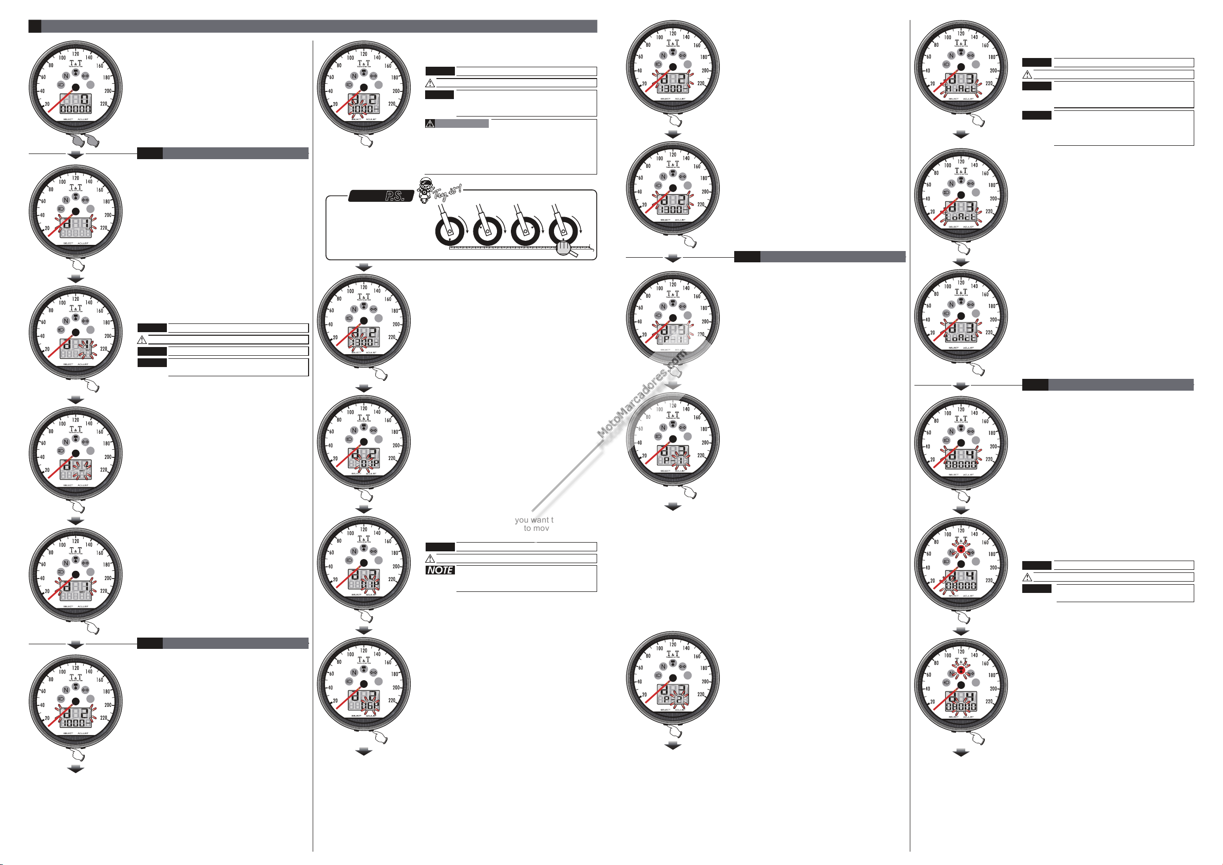
●Press the button one time to enter the
speed unit setting
Select
●
●
Press the Select button once to go back to
the Speed unit setting screen.
EX. The Speed unit setting is changed
from km/h to MPH.
●Press the Adjust button once to go back to
the tire circumference and sensor point
setting screen.
●
●
EX.To change the setting from km/h to
MPH.
Press the Adjust button to change the
setting.
Setting range: km/h or .MPH
●Press the Select button one time to enter the
tire circumference setting
●
●Press the Select button to move to the digit
you want to set.
EX. The tire circumference is 1,300 mm.
●Press the Adjust button once to go back to
the RPM pulse and input signal setting
setting screen.
4-3
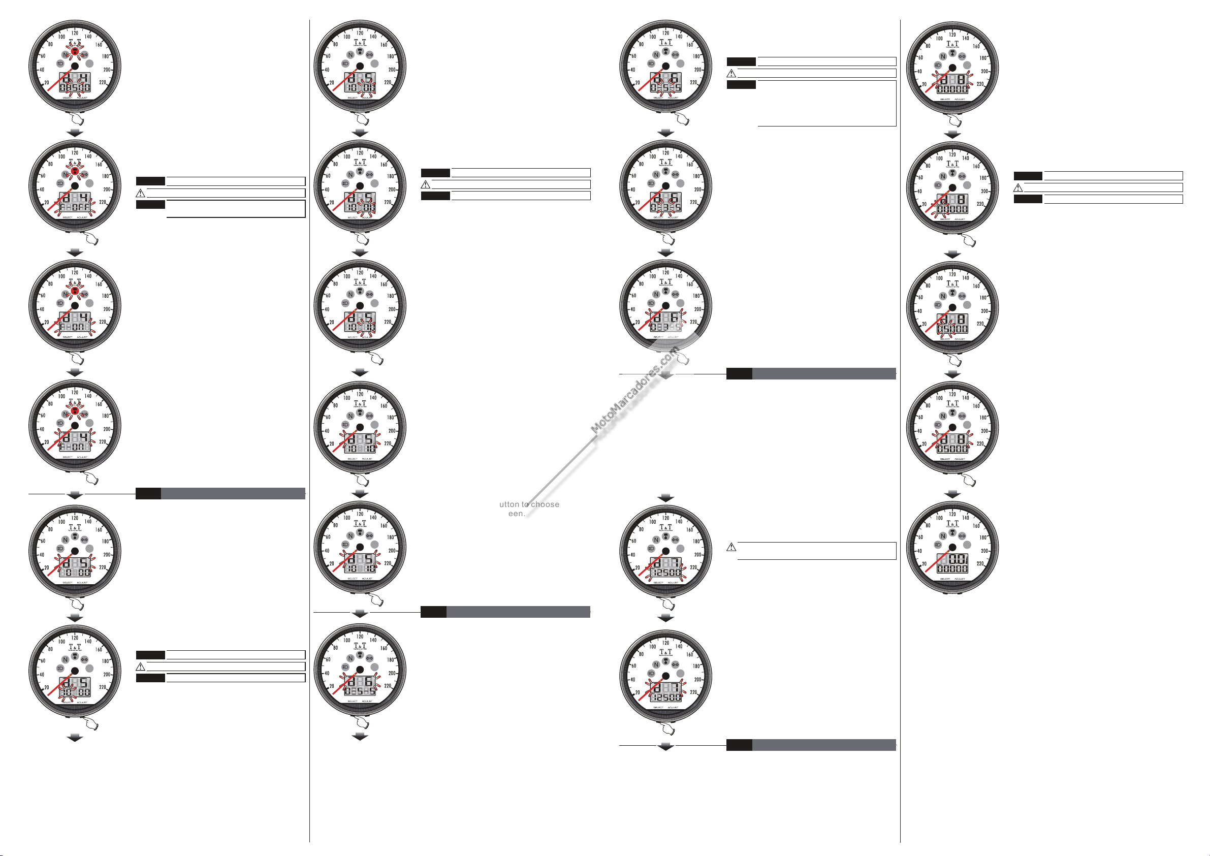
●Press the button one time to enter
the RPM pulse setting.
Select
●Press the Adjust button to choose the
setting number.
●Press the Adjust button to choose the
setting number.
●
●
Press the Select button once to go back to
the RPM pulse and input signal setting
screen.
EX. The input signal setting is changed
from HiAct to LoAct.
4-4
●Press the Select button one time to enter
the Shift light setting.
●
●
EX: You want the shift light to light on at
8000 RPM Please change the shift light
setting value to 8500 directly.
Press the Select button to move to the digit
you want to set.
●Press the Adjust button once to go back to
the shift light and shift light warning setting
setting screen.
●Press the Adjust button to choose the
setting number.
●
●Press the Select button to move to the
digit you want to set.
EX. The sensor point you want to set is 6.
●Press the Select button once to go back to
the tire circumference and sensor point
setting screen.
Function setting instruction
130
cm
You could define the valve
as the starting point and the
terminal point to measure
the wheel circumference
with a measuring tape.
●
●
Please measure the tire circumference (the tire you will
install the sensor on) and make sure the number of
magnet sensor point (You could install the magnet into
the disc screw or the sprocket screw.)
The speed displayed on the meter will be affected by
the setting, please make sure the setting number is
correct before you make the setting.
CAUTION!
The tire circumference setting range:
300~1,000 mm, and the digit you set is
from left to right in order.
●
●
Press the Select button once to go back to
the sensor point setting screen.
EX. The tire circumference setting is
changed from 1,000 mm to 1,300 mm.
The sensor point setting range:
1~20 points. You could change the
setting from left to right.
If the tachometer can't detect the
signal (No RPM is displayed on the
screen), you could choose another
setting, and check it again.
The impulse setting range is
between Hi (the positive impulse)&
Lo (the negative impulse)
●
●
EX. We would like to change the setting
to LoAct. (The negative impulse)
Press the Adjust button to choose the input
signal you want to set.
The tire circumference and sensor point setting.
RPM pulse and settinginput signal
NOTE
註Default:km/h
NOTE
NOTE
NOTE
註Default:1,000 mm
NOTE
Default:HiAct
註
NOTE
註
NOTE
註
NOTE
註
註
Default:8,000RPM
NOTE
NOTE
註Default:01P
NOTE
●In main screen, hold pressing the Select +
Adjust button for 3 seconds to enter the
setting screen.
Speed unit setting
Shiftlight setting
Now the d is flashingefault
Now the d is flashingefault
Now the d is flashingefault
Now the d is flashingefault
Now the d is flashingefault
The odometer & trip meter will change
together with the speed unit.
●
“ ”
●
●
●
●
●
–
●
●
Enter the number of ignition signals per
crankshaft revolution ( P value).
This may vary according to the vehicle
manufacturer/model and type of engine:
If a 4-stroke engine fires at every second
crankshaft revolution, enter P=0.5 (on 1-,
2- and 3-cylinder 4-stroke engines with one
ignition coil for each cylinder)
If a 4-stroke engine fires once per crankshaft
revolution, enter P=1 (on 2-, 4- and 6-cylinder
4-stroke engines with one ignition coil for two
cylinders)
2-stroke engines fire once per crankshaft
revolution; enter P=1
In the case of vehicles which have a
distributor (mostly cars), you can enter P
values up to 4, according to the number of
cylinders.
If you do not know how often your engine
fires per crankshaft revolution, start by
assuming the standard setting (P=1) the
instrument cannot be damaged if you do
this. If an incorrect engine
rpm is displayed, you should vary the P value
by entering it manually until the figure
displayed is realistic.
Example illustration: The setting is changed
from P=1 to P=2.
Press the selection button and change to the
function for setting the shift warning
Cortesia de www.marcadoresdemoto.com
Cortesia de www.marcadoresdemoto.com