Marcegaglia Buildtech N2W2 User manual
Barriera N2W2 Bordo Laterale / N2BL-MARC2014
MANUALE DI INSTALLAZIONE
Barrier System N2W2 Lateral verge / N2BL-MARC2014
INSTALLATION MANUAL
NORWAY
Manuale di Installazione Rev.002 –Nov.2015
Redatto da : Mauro ing. Monteleone
Controllato da : Molinari ing. Giacomo
Approvato da : Mauro ing. Monteleone

Sommario
1. Generalità
2. Condizioni di installazione
3. Operazioni preliminari.
4. Installazione dei Pali
5. Installazione della Barriera
6. Montaggio in curva.
7. Ispezioni-Manutenzione.
8. Ripristino dispositivo.
9. Durabilità
10. Riferimenti Normativi e Tecnici.
11. Allegati ed Annessi
Contents
1. General
2. Installation Conditions
3. Getting Started.
4. Installation of Posts
5. Installation of the Barrier
6. Assembly by curves.
7. Inspection-Maintenance.
8. Device. restore
9. Durability
10. Standards and Technicians.
11. Attachments and Annexes
1. Generalità
Il presente documento rappresenta il manuale di montaggio della barriera metallica con
nastro a 2 onde denominata N2BL-MARC2014 (N2W2).
Tutte le operazioni descritte e i tempi sono stati studiati per il corretto montaggio e
funzionamento della barriera, ogni modifica dovrà essere concordata e autorizzata da
Marcegaglia Buildtech s.r.l.

Da curare in particolare i tempi di serraggio completo delle viti necessarie per evitare
problemi di assemblaggio nelle fasi successive.
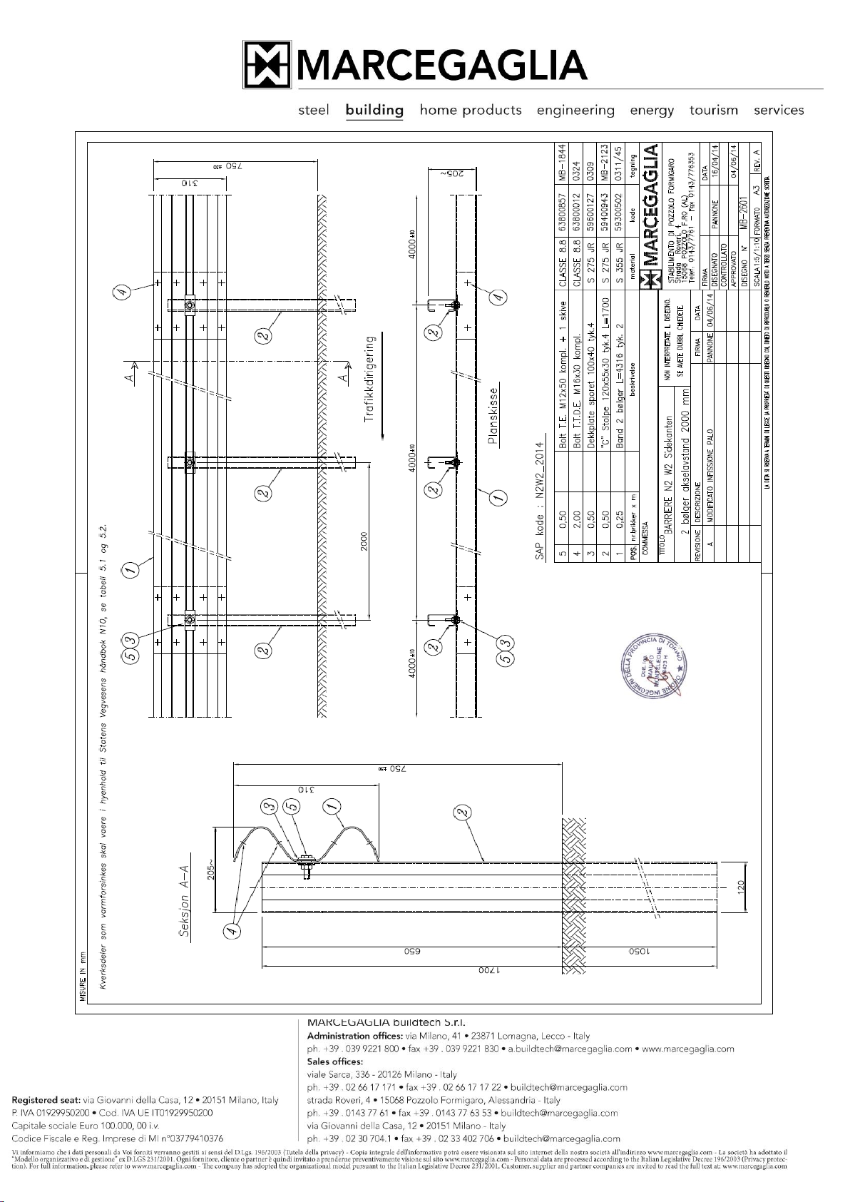
In dettaglio il dispositivo (vedi complessivo N2BL-MARC2014) è costituito da :
- Fascia 2 onde sp. 2 mm Pos. 1
- Palo a C 120x55x30 sp.4 mm Pos. 2
1. General
This document represents the manual of installation of the steel safety barrier system
with 2 waves rail called N2BL-MARC2014 (N2W2).
All of the operations and the times were studied for a correct installation and
operation of the barrier, any changes must be agreed and authorized by Marcegaglia
Buildtech Ltd.
To be treat in particular the times for the fully tighten of the screws required, to avoid
assembly problems in the later stages.
In detail the device (see overall N2BL-MARC2014) is constituted by:
- Rail 2 waves thkn. 2 mm - Pos. 1
- C-post 120x55x30 thkn.4 mm - Pos. 2
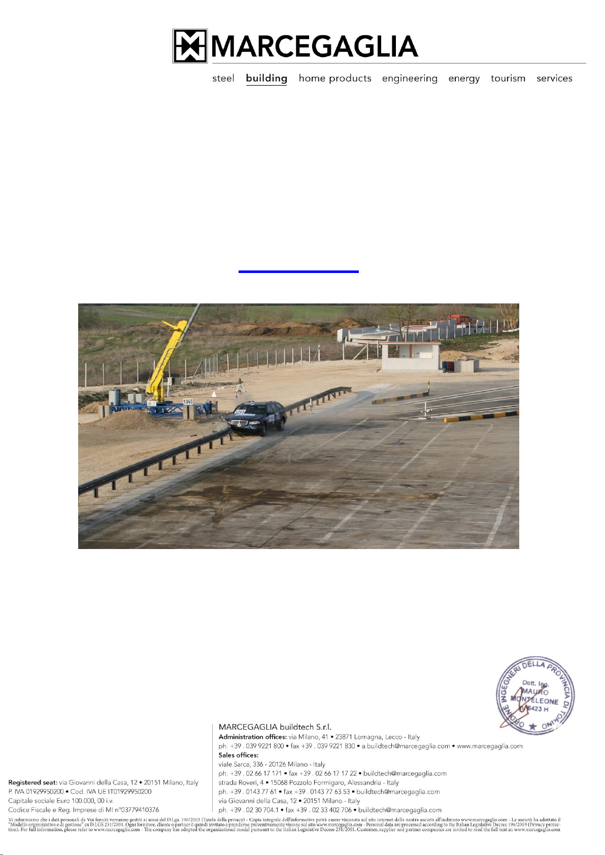
2. Condizioni di installazione
La barriera N2BL-MARC2014 è stata studiata espressamente per l’uso come bordo laterale
da installare su terra.
Si deve verificare l’accessibilità all’area di installazione con il veicolo battipalo e l’assenza di
ostacoli sia al di sopra che al di sotto della superficie (alberi, muri oppure condutture,
sottoservizi ecc.).

2. Installation Conditions
The barrier N2BL-MARC2014 was studied expressly for use as a side edge to be
installed on the ground.
One must check the accessibility of the area of installation with the typical pile driver
and the absence of obstacles both above and below the surface (trees, walls or
pipes, underground etc.).
3. Operazioni preliminari.
Per una efficiente installazione si consiglia di iniziare posizionando a terra il materiale
necessario lungo la linea di installazione della barriera.
In particolare, definita la tratta da installare, si consiglia di posizionare a terra e in
orizzontale le fasce a due onde con il filo lungo la linea di posizionamento dei pali.
Il posizionamento è da realizzarsi in modo preciso soprattutto in corrispondenza della
sovrapposizione delle fasce.
A questo punto si può procedere ad infiggere il primo palo della tratta con il mezzo battipalo
e quindi si tende una lenza che assicura il corretto allineamento dei pali successivi.
Durante l’infissione del primo palo deve essere anche curata la quota in modo da ottenere
la corretta altezza della barriera finita.
Normalmente, raggiunta la quota richiesta, viene evidenziata la posizione raggiunta
dell’utensile battipalo in modo da avere un riferimento preciso per l’infissione di tutti gli altri
pali.

3. Getting Started.
For efficient installation is recommended to start by placing on the ground the
necessary material along the line of barrier installation.
In particular, defined the section to be installed, you may want to place on the ground
and in horizontal the 2 waves rails with a wire along the line of positioning of the
posts.
The positioning is to be carried out in a precise way, especially in correspondence of
the overlap of the rails.
At this point you can proceed to fix the first post with the pile driver and then you
tend a wire that ensures correct alignment of the successive posts.
During the insertion of the first pole must also be taken care of the portion so as to
obtain the correct height of the barrier installed.
Normally, reached the required height, the position reached is marked on the pile
driver in order to have a precise reference for the driving of all the other posts.
4. Installazione dei pali
Avendo osservato le prescrizioni di cui sopra, il posizionamento dei pali diventa
rapido e preciso in quanto :
- il passo longitudinale è dato dalla posizione dei fori sulle fasce adagiate al suolo
- l’allineamento è assicurato dalla lenza

- la quota di infissione è assicurata dal riferimento sul battipalo.
La quota verticale della testa del palo può essere errata per una misura pari a +/- 2 cm in
quanto esistono opportune asole per installare correttamente il nastro a 2 onde.
La verticalità del palo nelle due direzioni è da curare ed è ottenuta tramite opportuni
spostamenti della macchina battipalo.
4. Installation of the posts
Having observed the above requirements, the positioning of the posts becomes rapid
and precise as:
- The longitudinal posts distance is given by the position of the holes on the rails
lying on the ground
- The alignment is assured by the line
- The share of piling is ensured by reference to the pile driver.
The vertical measurement of the head of the pile can be mistaken for a measure of +/-
2 cm as there are appropriate slots to properly install the 2 waves rail.
The verticality of the post in the two directions is to treat and is obtained by
appropriate movement of the machine pile driver.
5. Installazione della barriera
Viene sollevata la fascia a 2 onde (avendo cura di iniziare dal fondo della tratta in modo da
ottenere la corretta sovrapposizione delle fasce) e viene fissata solo al primo palo ed al palo
intermedio.
Il bullone corrispondente al terzo palo viene posizionato solo quando viene sovrapposta la
fascia successiva; questi collegamenti sono formati da bullone M12, dado, rondella e
piastrina rettangolare di protezione asola da posizionare davanti alla fascia a 2 onde.
A questo punto è anche possibile mettere in opera i bulloni di collegamento delle fasce ( 8
completi di dado e rondella).

Terminato il montaggio della tratta è necessario allineare verticalmente le fasce in modo da
ottenere tutta la barriera alla stessa altezza o comunque alla stessa distanza dal piano
stradale.
Normalmente questa operazione viene effettuata traguardando la prima fascia e
correggendo via via le successive serrando i bulloni che collegano il nastro al palo con una
coppia maggiore o uguale a 10 Nm .
Successivamente è possibile serrare i bulloni di collegamento tra le fasce a 2 onde ad una
coppia maggiore o uguale a 40 Nm .
All’inizio ed alla fine di ogni tratta deve essere installata una bandella diagonale di
irrigidimento (pos. 7) vincolata al piede del palo con una barra filettata M24 completa di due
dadi e piastrine da serrare ad una coppia maggiore o uguale a 40 Nm.
5. Installation of the barrier
The 2 waves rail is raised up (taking care to start from the end of the route section in
order to obtain the correct overlapping of the rails) and is fixed only to the first post
and the intermediate post.
The bolt corresponding to the third pole is placed only when the next band is
overlapped; these connections are formed by M12 bolt, nut, washer and rectangular
slot covering plate to be positioned in front of the 2 waves rail.
At this point it is also possible to implement the bolts connecting the rails (8
complete with nut and washer).
After completing the installation it is necessary to line up vertically the rails so you
get all the barrier at the same height or at least the same distance from the road
surface.
Normally this is done by sighting the first rail and gradually correcting subsequent
tightening the bolts that connect the rails to the posts with a torque greater than or
equal to 10 Nm.

You can then tighten the bolts connecting the 2 waves rails in order to a couple
greater than or equal to 40 Nm.
At the beginning and end of each section must be installed in a diagonal stiffening
band (pos. 7) fastened to the foot of the post with a threaded rod M24 with and two
nuts and washer to be tightened to a torque greater than or equal to 40 Nm.
6. Montaggio in curva
La barriera in oggetto può essere montata anche in tratti curvi aventi raggio di curvatura
minimo pari a 40 m, sono presenti opportune asole che permettono l’installazione
utilizzando i particolari standard.
Al di sotto della misura indicata è necessario provvedere alla calandratura delle fasce e
quindi è necessario un rilievo in situ ed un disegno specifico.
6. Assembly at curved sections
The barrier in question can also be mounted in curved sections with minimum
bend radius of 40 m, are appropriate slots that allow the installation using the
standard components.
Below the indicated size of radius is necessary to provide for the calendering of
the bands and therefore requires a relief in situ and a specific design.
7. Ispezioni- Manutenzione
La barriera in oggetto non necessita, in condizioni di uso normali, di manutenzione.
Si consiglia di verificare ogni due anni il serraggio dei bulloni in caso di vibrazioni dovute
al traffico, possono presentarsi allentamenti.
In questo caso è richiesto un successivo serraggio per riportare la coppia a quanto
sopra richiesto.

7. Inspection - Maintenance
The barrier in question doesn’t need, in normal conditions of use, any particular
maintenance.
It is advisable to check every two years, the tightening of the bolts in the case of
vibrations due to traffic, there may be loosening.
In this case it is required to bring a subsequent tightening torque to the above
required.
8. Ripristino dispositivo
In caso di incidente è necessario ripristinare il dispositivo danneggiato.
In relazione alla severità dell’impatto subito è possibile sostituire gli elementi danneggiati, a
partire dalle fasce 2 onde fino a sostituire i pali.
In linea di massima si consiglia di sostituire tutta la barriera danneggiata a partire da una
campata prima del primo elemento deformato (4 m) e fino a una campata dopo l’ultimo
elemento danneggiato.
Si consiglia anche di compattare il terreno dove vengono estratti i pali da sostituire.
8. Device Restore
In case of accident you need to restore the damaged device.
In relation to the severity of the impact right away, you can replace the damaged
items, starting from the 2 waves rails up to replace the posts.
In principle, it is advisable to replace the whole barrier damaged from a span before
the first element deformed (4 m) and up to a span after the last element damaged.
You should also compact the soil where you extracted the posts you replace.

9. Durabilità
Tutti gli elementi sono trattati con processo di zincatura a caldo secondo la UNI 1461, con
spessori minimi e ricoprimento in funzione degli spessori dei vari elementi.
9. Durability
All elements are treated with hot dip galvanizing process according to UNI 1461, with
minimum thickness and coating according to the thickness of the various elements.
10. Riferimenti Normativi e Tecnici
UNI EN 1317-5 /2007 (barriere di sicurezza stradale)
UNI EN 22768: 1996 (tolleranze)
10. Applicable Standards and Technical
UNI EN 1317-5 / 2007 (road safety barriers)
UNI EN 22768: 1996 (tolerances)
11. Allegati ed annessi
Disegno complessivo N2BL-MARC2014 / N2W2 / dwg. MB-2601.
11. Attachments and annexes
Overall design N2BL-Marc 2014 / N2W2 / dwg. MB-2601.
This manual suits for next models
1
Table of contents
Other Marcegaglia Buildtech Construction Equipment manuals


