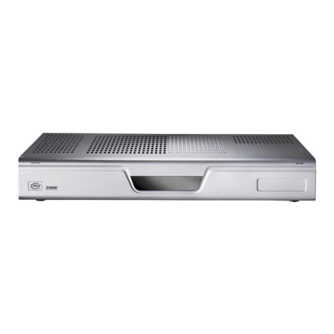
March Networks 3108 User manual

3108 DVR
Installation Guide
TRANSF O RMING THE W A Y Y O U VIE W Y O UR BUSINESS

About March Networks
March Networks (TSX:MN; AIM:MNW) is a leading provider of innovative IP-based video
applications used for security surveillance and monitoring. Our software and hardware
solutions allow businesses to increase operational efficiencies, address risk, and manage
assets with an integrated set of video-based intelligence tools that support enhanced
decision-making. Today the ISO 9001:2000 certified company serves the needs of leading
banks, retail organizations and transportation authorities in more than 40 countries
throughout the world. For more information, please visit: www.marchnetworks.com.
Committing to Protect the Environment
March Networks is committed to doing our part to protect the environment. As a result, we
have embraced the RoHS and WEEE Directives in the design and manufacture of our
products. You can review further details at the following location on our corporate Web site:
http://www.marchnetworks.com/User_Files/Downloads/Products/RoHS-
WEEE_Compliance_Statement_12-06.pdf.
Accessing Customer Care
For technical support and assistance, contact us at:
•
Telephone: 1-613-591-1441
•
Toll free: 1-800-472-0116
•
Fax: 1-613-591-1858
•
E-mail: Te c h s u p p o r t @ m a r c h n e t w or k s . c o m
Providing Documentation Feedback
At March Networks, our goal is to produce documentation that is technically accurate and
informative. If you have comments or suggestions about our online Help and
documentation, you can e-mail us at: techwriters@marchnetworks.com.

© 2006. March Networks Corporation. All rights reserved. MC-14011 Rev. 4.0
Information in this document is subject to change without notice. MARCH NETWORKS and the
MARCH NETWORKS logo are trademarks of March Networks Corporation. Windows® is a registered
trademark of Microsoft Corporation. All other trademarks are the property of their respective owners.
The software described in this document is furnished under a license agreement or nondisclosure
agreement. The software may be used or copied only in accordance with the terms of those agreements.
The contents of this manual and accompanying software are protected by copyright. No part of this
publication may be reproduced, stored in a retrieval system, or transmitted, in any form or by any means,
electronic, mechanical, recording, or otherwise without the prior written permission of March Networks
Corporation.


Contents
ii
Mandatory Regulations ....................................................................................................................... iii
Electromagnetic Interference (EMI) Information ................................................................................................ iii
Power Cord Notice ................................................................................................................................................ iii
DVR Servicing Notice ............................................................................................................................................. iii
Shipping Notice ..................................................................................................................................................... iii
Introducing the 3108 DVR ..................................................................................................................... 1
Installation Considerations .................................................................................................................................... 2
About March Networks ......................................................................................................................................... 2
Accessing Customer Care ....................................................................................................................................... 2
Exploring the 3108 DVR ........................................................................................................................ 3
Unpacking the DVR ................................................................................................................................................ 3
Equipment Specifications ...................................................................................................................................... 4
Front of the DVR .................................................................................................................................................... 4
Health and Status LED Information .................................................................................................................. 5
Bottom of the DVR ................................................................................................................................................. 5
Inside the DVR ........................................................................................................................................................ 6
I/O Panel ............................................................................................................................................................. 6
Auxiliary I/O Panel ............................................................................................................................................. 8
Hard Drive Bracket ............................................................................................................................................. 9
Rear of the DVR ...................................................................................................................................................... 9
Mounting the DVR and Installing a Hard Drive ................................................................................ 11
Grounding the DVR .............................................................................................................................................. 11
Removing or Replacing the Front Cover ............................................................................................................. 13
Removing the Hard Drive Mounting Bracket ..................................................................................................... 15
Marking the DVR Location .................................................................................................................................. 16
Items Required to Wall-Mount the DVR ........................................................................................................ 16
Pulling Wires and Cables to the DVR .................................................................................................................. 19
Wall-Mounting the DVR ...................................................................................................................................... 20
Installing a Hard Drive ......................................................................................................................................... 20

Contents
ii
Making DVR Connections .................................................................................................................. 23
Connecting Video Cameras .................................................................................................................................. 24
Connecting a Video Output Device ..................................................................................................................... 26
Connecting Audio Input and Output Devices ..................................................................................................... 27
Connecting Alarm Sensor Devices ....................................................................................................................... 28
Connecting a Switch Device ................................................................................................................................. 29
Connecting Dataport Devices .............................................................................................................................. 31
Connecting to the Network ................................................................................................................................. 35
Connecting a USB Modem ................................................................................................................................... 36
Powering the DVR ............................................................................................................................... 37
Connecting the AC Power Cord ........................................................................................................................... 37
Applying AC Power .............................................................................................................................................. 38
DVR Access and Configuration ............................................................................................................................ 38
Maintaining and Servicing the DVR .................................................................................................. 39
Replacing a Fuse ................................................................................................................................................... 39
Reference: Working With Removable Terminal Blocks .................................................................... 41
Connecting Wires to Terminal Blocks .................................................................................................................. 41

3108 DVR Installation Guide
iii
Mandatory Regulations
You should be familiar with the mandatory regulations governing the product’s operations. You should
also adhere to these instructions to ensure you meet regulatory compliance.
Electromagnetic Interference (EMI) Information
Canada - Industry Canada
This Class A digital apparatus meets all requirements of the Canadian
Interference-Causing Equipment Regulations. Cet équipement a été testé et certifié conformément aux
limites imposées par la réglementation en vigueur pour un équipement numérique de classe A.
United States - Federal Communications Commission
This equipment has been tested and
found to comply with the limits for a Class A digital device, pursuant to Part 15 of the FCC Rules. These
limits are designed to provide reasonable protection against harmful interference in a commercial
environment. This equipment generates, uses, and can radiate radio frequency energy, and if not
installed and used in accordance with the installation guide, is liable to cause harmful interference to
radio communications. Operation of this equipment in a residential area is likely to cause harmful
interference, in which case users will be required to correct the interference at their own expense.
Power Cord Notice
DVR Servicing Notice
Shipping Notice
WARNING!
A power cord is provided with a grounded attachment plug. To avoid electrical shock, always use the power
cord and plug with a properly grounded outlet. To maintain safety compliance, ensure the power cord has
the appropriate safety approvals for the country in which the equipment is to be installed.
WARNING!
The procedures contained in this publication outline how to install or service components located inside
the DVR, requiring the removal of the DVR cover. Installation and maintenance procedures requiring
internal unit access are to be performed by qualified service personnel only.
WARNING!
Shipment of the DVR and components may expose the unit to temperature extremes. We recommend you
allow the unit to return to room temperature prior to operation.


1Section
1
Introducing the 3108 DVR
The 3108 DVR is an eight camera digital video recorder that provides you with a complete video
surveillance system. The DVR captures live, scheduled, or event-driven video, allowing you to monitor
your environment and investigate activity.
The DVR’s convenient wall-mount design allows you to quickly install the unit in its desired location.
All device connections, such as the connection to video cameras, a video output device, and alarm
sensor devices, are made inside the DVR. Device cables can be easily pulled through the wall into the
unit and hidden away.
Initial configurations can be performed at the DVR site to set up the DVR’s network connection. The
DVR’s built-in provisioning interface (a software application running on the unit that you use to
configure the DVR’s general settings) lets you set up the network connection by specifying the DVR’s
network settings. Once configured, the DVR can be accessed remotely over a network connection. Or, if
you connect a USB modem to the unit, it can be accessed remotely over a dial-up connection.
While the DVR requires minimal maintenance, this publication does provide steps for servicing the
DVR’s internal components and installing a hard drive.
When you install a hard drive in the DVR, audio, video, and alarm events are stored on the DVR. You
can retrieve archived audio, video, and alarm events stored on the DVR using the administration and
configuration software applications included on your March Networks software CD.

2
Introducing the 3108 DVR
Installation Considerations
Before you install the DVR, follow these steps:
1. Ensure anti-static precautions are taken.
Ensure proper use of an anti-static guard during installation to avoid damage to the DVR from
electrostatic discharge and to prevent personal injury.
2. Determine the location of the DVR.
This location should allow you to run cables to the devices, the power source, and the network.
3. Ensure the DVR is installed in the proper operating environment.
Do not locate the DVR in an area where the temperature rises above 100 degrees Fahrenheit (40
degrees Celsius) or falls below 50 degrees Fahrenheit (10 degrees Celsius).
Do not locate the DVR in an area of high humidity. Humidity must be less than 85 percent, non-
condensing.
Do not locate the DVR in a dirty or dusty area.
Mount the DVR on an inside wall with good air circulation, which is required for proper heat
dissipation.
About March Networks
March Networks™ (TSX:MN; AIM:MNW) is a leading provider of innovative IP-based video
applications used for security surveillance and monitoring. Our software and hardware solutions allow
businesses to increase operational efficiencies, address risk, and manage assets with an integrated set of
video-based intelligence tools that support enhanced decision-making. Today the ISO 9001:2000
certified company serves the needs of leading banks, retail organizations and transportation authorities
in more than 40 countries throughout the world. For more information, please visit
www.marchnetworks.com.
Accessing Customer Care
For technical support and assistance, contact us at:
If you purchased this product from a third-party organization, such as a March Networks certified
reseller, please contact the organization’s technical support staff.
Telepho ne : 1-613-591-1441
Toll free: 1-800-472-0116
Fax: 1-613-591-1858
E-mail: techsupport@marchnetworks.com

2Section
3
Exploring the 3108 DVR
Before you begin the installation process, become familiar with the DVR by reviewing the equipment
specifications outlined in this section.
Unpack the DVR and explore its physical layout, including the features at the front, rear, and bottom of
the unit. You can also remove the DVR cover to access the DVR’s internal components.
Figure 1: 3108 DVR
Unpacking the DVR
Ensure the following items are located within the DVR packaging:
Security key
Power cord
Terminal blocks (qty 3)
Examine the contents carefully for damage. If any item appears damaged, contact the shipping
company to make a claim. The shipping company can provide the claim forms.

4
Exploring the 3108 DVR
Equipment Specifications
The following table outlines the equipment specifications for the DVR, including the dimensions and
operating temperatures:
Front of the DVR
The front of the DVR is covered and has no external connections. You can remove the front cover to
access the DVR’s I/O panel, auxiliary I/O panel, and bracket for hard drive installation. For more
information about removing the DVR cover, see “Removing or Replacing the Front Cover” on page 13.
The unit’s health and status LEDs, which provide general information about the unit, can be viewed at
the front of the DVR.
Figure 2: Front of the DVR
Feature Specifications
Dimensions
Width:
14.5 inches; 36.8 centimeters
Height:
20 inches; 50.8 centimeters
Depth:
4.5 inches; 11.4 centimeters
Weight 15.0 pounds; 6.8 kilograms
Power input North American models: 120 volts AC 60 hertz
European models: 240 volts AC 50 hertz
Power consumption 60 watts (typical), including video camera power (eight video
cameras) and audio input and output device power
Operating temperature 50 to 104 degrees Fahrenheit; 10 to 40 degrees Celsius
Screws
Health
and Status
LEDs

3108 DVR Installation Guide
5
Health and Status LED Information
The following table outlines health and status LED activity:
Bottom of the DVR
At the bottom of the DVR you can access the AC power cord port, to which the DVR power cord
connection is made. For more information about connecting the AC power cord and applying power to
the DVR, see “Powering the DVR” on page 37.
You can also access the ground stud, to which the grounding connection is made. The grounding
connection protects the DVR from electrostatic discharge and prevents personal injury. For more
information, see “Grounding the DVR” on page 11.
There are cable punchouts at the bottom of the DVR that you can use to pull wires and cables into the
DVR. When pulled through the cable punchouts, the wires and cables are not hidden out of the way.
Please note that if you use the cable punchouts, you must use a cable strain relief. For more
information, see “Wall-Mounting the DVR” on page 20.
LED Activity Function
Unit
Green Unit is operating properly.
Yellow Unit is powering up or powering down.
Red Unit detects a hardware problem.
Operation
Green Unit is operating properly (solid); unit is
powering up (flashes).
Yellow
Unit is functional, but a problem is detected;
the LED turns off when the problem is
acknowledged using the administration and
configuration software applications included
on your March Networks software CD.
Red
Indicates CD burning status. For more
information, see the Using a CD-RW Drive
With a DVR Technical Instructions.
HD Green Unit is logging video (flashes). This LED also
flashes while the unit is powering up.
WARNING!
When live AC power is connected to the DVR, +24 volts AC power is also live. Before you access
any components located inside the DVR, move the power switch on the auxiliary I/O panel to
the OFF position. After the health and status LEDs turn off, remove the power cord from the
DVR to prevent injury.

6
Exploring the 3108 DVR
Figure 3: Bottom of the DVR
Inside the DVR
All device connections are made through the connectors and terminal blocks on the DVR’s I/O panel
and auxiliary I/O panel. The auxiliary I/O panel also contains a provisioning port to which you can
connect a computer or PDA so you can configure the DVR’s settings. For more information about
configuring the DVR’s settings, see “DVR Access and Configuration” on page 38.
I/O Panel
Figure 4 and the table on the following page outline the I/O panel location and connectors.
AC Power Cord
(shown connected)
Ground Connection

3108 DVR Installation Guide
7
Figure 4: Inside the DVR — I/O Panel
Item Connection Description
A Video inputs Connects up to eight video cameras.
B Terminal blocks
Provides connections for the following devices:
•Power wires for up to eight 12 volts DC 200 mA video cameras
(unit must not power more than eight video cameras)
•Two audio input and output devices (for example, an intercom
unit with line level audio input/output and 150 mA power
maximum, both devices combined)
•Four alarm sensor devices
•One PTZ camera or passthrough dataport device
(RS-485)
•One switch device
CVideooutput Connects one video output device (for example, a video
monitor).
DUSB Connects to a USB modem for dial-up connection.
EEthernet Connects to an Ethernet network for network connection.
Inside DVR
(Front cover removed)
I/O Panel

8
Exploring the 3108 DVR
Auxiliary I/O Panel
Figure 5 and the accompanying table outline the auxiliary I/O panel location and connectors:
Figure 5: Inside the DVR — Auxiliary I/O Panel
Item Connection Description
A Terminal block
Provides power for up to eight video cameras (+24 volts AC at
up to 250 mA).
(Unit must not power more than eight video cameras).
B Fuses and Fuse LEDs AC video camera supply lines are individually fused. Fuse status
is indicated by the fuse LED.
C Health and status LEDs Indicates the DVR’s health and status.
DPowerswitch Turns the DVR on and off.
F
Inside DVR
(Front cover removed)
Auxiliary
I/O Panel

3108 DVR Installation Guide
9
Hard Drive Bracket
The DVR’s hard drive mounting bracket, which can be accessed by removing the DVR front cover, is
used to securely mount one hard drive inside the DVR.
The DVR is shipped without hard drives. For more information about installing a hard drive, see
“Installing a Hard Drive” on page 20.
Rear of the DVR
At the rear of the DVR you can access the rear cutout, which lets you pull the required wires and cables
into the unit so they can be connected to the DVR. Pulled wires are hidden, which prevents tampering.
Figure 6: Rear of the DVR
E Dataport Connects an ATM to the DVR. This is an RS-232 serial port.
F Provisioning port Connects a computer or PDA to the DVR for initial unit
configuration. This is an RS-232 serial port.
Item Connection Description
Rear of DVR
Rear Access
Cutout


3Section
11
Mounting the DVR and Installing a Hard Drive
Before you connect devices to the DVR, you must mount the unit on the wall. Begin by grounding the
DVR to protect the unit from electrostatic discharge and to prevent personal injury. The DVR must be
properly grounded at all times during the installation. For more information, see “Grounding the
DVR” on page 11.
Remove the DVR front cover and hard drive mounting bracket so you can access the components
required for mounting. Mark the DVR’s location on the wall and pull the device wires and cables into
the unit so you can connect devices to the unit. Finally, install a hard drive in the unit.
Grounding the DVR
To protect the DVR from electrostatic discharge and to prevent personal injury, ground the DVR before
you mount it. The preferred grounding method, described here, is to connect a ground wire between
the DVR and an earth ground source.
WARNING!
The mounting methods and materials described in this section are the preferred mounting
methods and materials.
Always mount the DVR vertically.
The procedures contained in this section outline how to install or service components located
inside the DVR, requiring the removal of the DVR cover. Installation and maintenance
procedures requiring internal unit access are to be performed by qualified service personnel
only.
You cannot service the DVR’s internal power supply or any components covered by the metal
plates. The fuse labelled “F1” under this plate is not serviceable. Please send the unit back to the
manufacturer or service dealer to replace the parts. Removing the metal plates voids the DVR’s
warranty and may cause personal injury.
WARNING!
To ensure personal safety and proper grounding, do not physically install the DVR, connect
devices, service, or maintain the DVR’s internal components while the DVR is powered or
connected to a wall outlet or powered uninterruptible power supply (UPS).

12
Mounting the DVR and Installing a Hard Drive
To connect a ground wire
1
Locate the ground stud at the bottom of the DVR, near the power cord connector.
2
Prepare an earth ground wire of appropriate length using a proper ground wire and a solderless
ring connector. Strip ½ inch of insulation from the end of the wire, and then crimp the ring
connector onto the wire.
3
Connect the ground wire to the DVR ground stud by applying these parts in the following order,
as shown below:
• Solderless ring connector (with attached 18-gauge ground wire)
•Kepsnut
4
Connect the other end of the ground wire to an earth ground source.
Figure 7: Connecting a Ground Wire to the DVR
After you ground the DVR to an earth ground source, ground yourself to the DVR chassis with an anti-
static wriststrap.
Figure 8: Connecting a Grounding Wriststrap
Ground Stud
Keps Nut
Ground Wire
From Earth
Ground Wire
Connection
Ground Source
(18-gauge)
Clip
Ground Stud
To Wr iststrap
Table of contents
Other March Networks DVR manuals

March Networks
March Networks HNVR MS Series User manual

March Networks
March Networks 8516 Series User manual

March Networks
March Networks CD-13887 Owner's manual

March Networks
March Networks 8724 V Tribrid NVR User manual

March Networks
March Networks 8732 R, 8532 R User manual

March Networks
March Networks 8000 Series User manual
Popular DVR manuals by other brands

Wirepath
Wirepath WPS-365-DVR Installation and user manual

Bosch
Bosch DVR600 Series Installation and operation manual

Panasonic
Panasonic AG-MDR15P operating instructions

UNIVIEW
UNIVIEW NVR202-16E user manual

Vista
Vista QNVR04P Installation and user manual

Channel Master
Channel Master DVR+ quick start guide